Surface modeling Aston Martin ONE-77
Surface Modeling Of Aston Martin ONE-77
OBJECTIVE: Aim of this project is to surface model Aston Martin One-77 in Solidworks.
INTRODUCTION: SOLIDWORKS is a solid modeling and computer aided design software which also enables user to do surface modeling. Surface modeling in solidworks can be a challenge for many users as it requires a good knowledge of the software, its tools and most importantly, patience. In this project we made a surface model of Aston Martin One-77 car with basic knowledge and few new techniques. Apart for making surfaces, we also used basic surface modeling techniques to make few parts of the car.
DESIGN METHODOLOGY
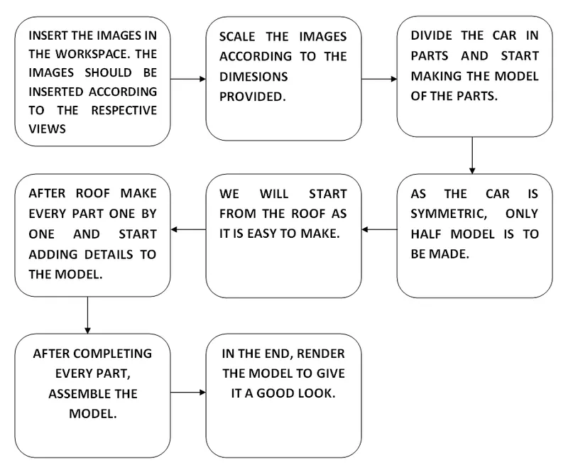
DESCRIPTION: Entire care is divided into following parts:
- Car body/ Frame
- Hood
- Doors
- Windshield
- Rear windshield
- Rear diffusers
- Grill
- Head lights
- Windows
- Emblem
- Wheels
As mentioned earlier, we made the entire model using surface modeling and solid modeling techniques, hence both tools were used. The parts on which surface modeling technique was used are frame, hood, doors, windshields, windows and headlights. The rest were made my solid modeling namely tire, disk, caliper and emblem.
Following tools were used for making the complete model.
FOR SKETCH:

- Sketch tool
- Line
- Circle
- Spline
- Rectangle
- 3 point arc
- Point
- Fillet (sketch)
- Text
- Slot
- Smart dimensions
- Convert entities
- Trim entities
FEATURES:

- Extrude boss/base
- Extrude cut
- Revolve boss/base
- Revolve cut
- Sweep boss/base’
- Sweep cut
- Fillet
- Linear pattern
- Circular pattern
- Curve driven pattern
- Mirror
- Intersect
- Shell
- Chamfer
- Intersect
- Reference plane
- Reference axis
- Split line curve
- Projected curve
- Move/Copy body
- Delete feature
- Flex
SURFACE:

- Extrude
- Sweep
- Boundary
- Fill
- Loft
- Fillet
- Offset
- Ruled surface
- Knit
- Move/copy
- Delete face
- Cut with surface
- Extend surface
FOR APPEARANCE
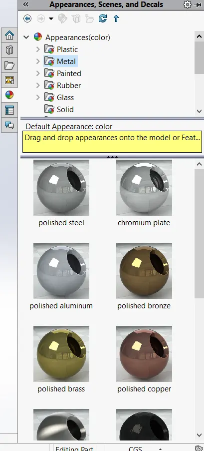
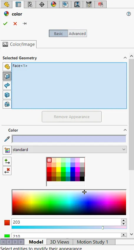
- Real view graphics
- Shadows in shaded mode
- Ambient occlusion
- Perspective
ASSEMBLY
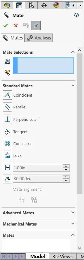
For assembly of the model we used mate tools
- coincident
- concentric
- distance
- width
Now let’s have a look at making of the model and a brief description of the tools used.
CAR BODY
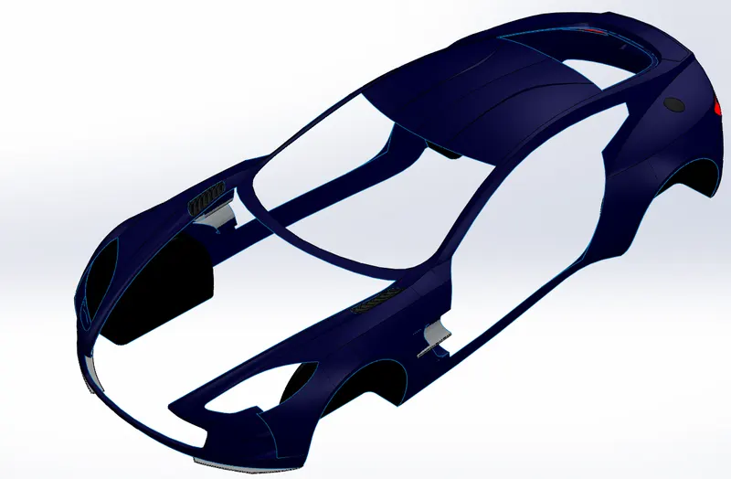
Like the entire car, this frame was also not made in one go but it was divided further. Roof was designed first then side of the body including fender (small portion above the wheel) was made. After that front and rear bumper was made. But it was a bit difficult task to make the details on the door and other details on the bumpers.
Spline tool is the basic tool here which is used to make curve. Using this tool we made curve taking the blueprint into account. To make boundary we have many approaches one of which we used in the starting for making roof was to make projected curve using 2 sketches. These 2 sketches were made on planes perpendicular to each other. Once the area is enclosed using projected curve or sketch or combination of the, boundary surface tool was used to make a surface out of them. This tool is generally used for making 4 sided surfaces hence the problem arose in the parts which had 5 or more edges like the area surrounding the front/rear fender and its vicinity. Here another useful tool surface fill was used. This tool fills the hole between the surfaces with a surface. A proper continuity has to be mentioned so that we get a good flow in a surface.
Once the surface modeling is finished, we can make different surfaces as one surface by using knit surface tool. This tool knits the surfaces together that is it makes n different surfaces as one surface. Black dashed line appears after knitting the surfaces.
Sometimes after knitting the surface we have to further add details to the model say to the rear lights but as we had knitted the surface it is acting like one surface and we cannot select the individual rear light, in this case to separate it from the body we use offset tool. This tool makes the copy of the selected surface at the specified distance. But to separate we follow the following process
- Make offset surface at 0cm
- Hide offset
- Delete face
- Make offset visible
Now delete face tool which is mentioned above is useful when we have to delete a face from the surface body. It deletes that specific face only.
Ruled surface tool adds extra surface of the specified length and method (method means the way user wants the new surface to be with respect to the existing surface like perpendicular, tangent etc).
Nobody prefers an edgy car. Keeping this in mind we should always make our model curvy. But what about the edges of the small surfaces or details? They also have to be made curved and fillet tool helps in that. This tool makes the sharp edge curved this making it look good and avoiding unnecessary injury (for real model).
Many times we have to split the surface into two or more, for this we can use split feature where we can specify the trim tool say sketch and the target body. It will thus split the surface in two.
Many such features were used for making the model like surface extend which extends the selected surface by the specified length, extrude surface to make a curve in a surface, delete/keep body feature to remove helpful but unnecessary after help bodies etc.
After completing the model, mirror tool was used to make it symmetric about a plane. Here we used right plane because obviously the car is symmetric about that plane.
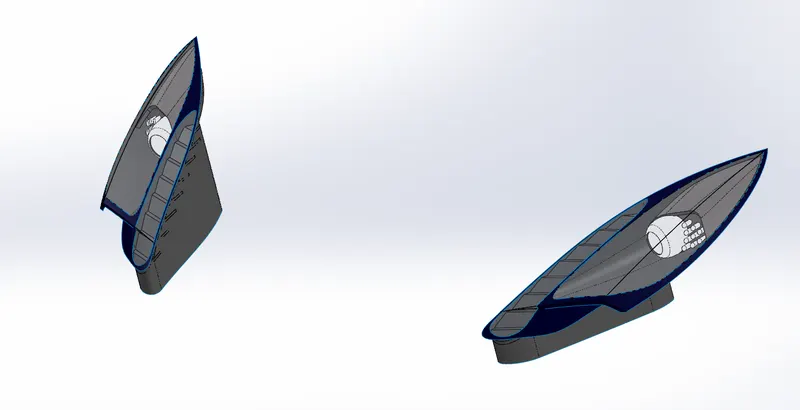
HEADLIGHTS:
For making this part we first separate it from the body like the 0cm offset method mentioned above and then, add details to it in other file. We have to ruled surface, thicken some parts of it in fact use solid modeling techniques in some details like lamp. Apart from that we use projected curve, surface boundary, surface fillet, surface fill, surface cut, move/copy body to complete this model.
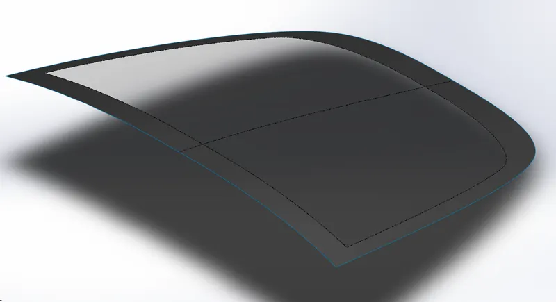
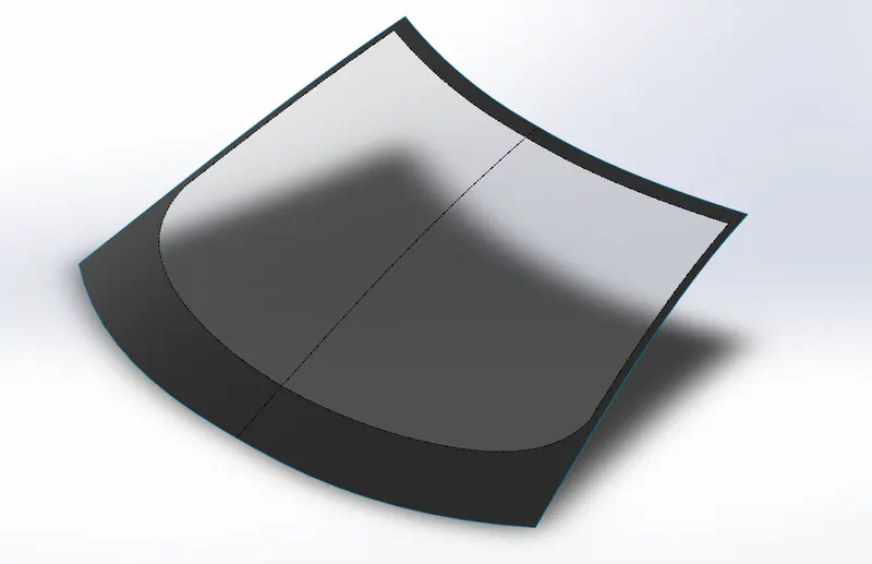
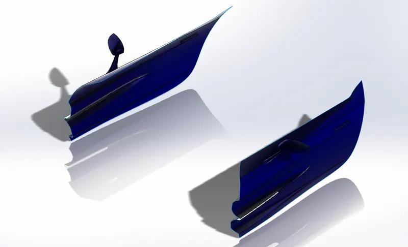
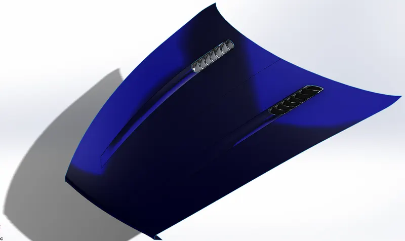
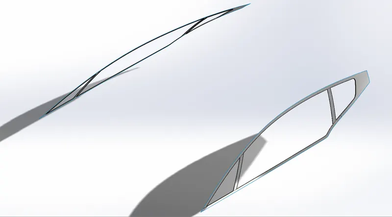
HOOD, WINDSHIELDS, WINDOWS
As while making the model we make it entirely and then separate few parts to further add details, these are few of those parts which we have made with body and then separated to complete it.
These parts are simple and require spline to make out line and then surface fill and boundary surface. Some parts are made using ruled surface and some details are made solid using thicken tool like the grill like part on the hood. Also to add more details so as to make the part look good visually split tool was used.
The transparency of the windows and wind shield is simply achieved by change transparency option.
GRILL
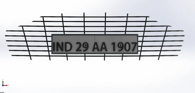
It is a good example of combination of surface and solid modeling. We first split the surface which we made as a front bumper. Then we use offset surface tool, surface extend tool and also extrude bass base tool to make grill structure and then intersecting it with the surface and cut with surface tool to achieve the grill. Fillets are applied all over the grill to make it look good.
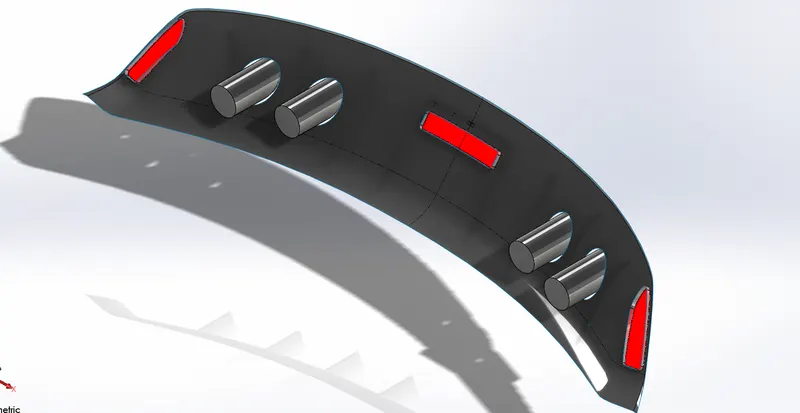
REAR DIFFUSER
This model was designed the same was the grill. After splitting from the main body apart from using surface tools like ruled surface , offset surface, fillet surface and cut with surface modeling tools like boss extrude, extrude cut, shell etc were used to make fins and exhaust.
WHEEL SUB ASSEMBLY
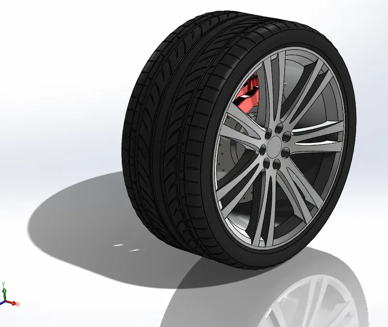
This model was made using solid modeling techniques. This is in fact an assembly of tire, rim, disk and caliper. Simple revolve sketch tool was applied to get the basic shape of the model and further to make the details tools like cut extrude, linear pattern, circular pattern, revolve cut were used.
While making rim, the entire spokes were not made. Rather a certain pattern was identified and later circular pattern was used.
EMBLEM
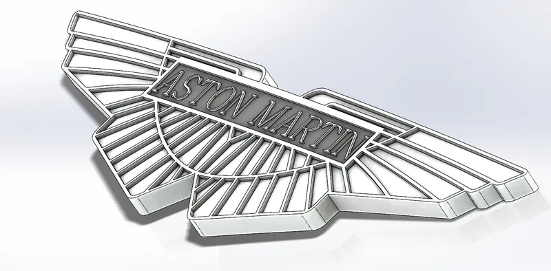
This detail gives a feeling of satisfaction after making the entire model. The beauty lies in the name itself. This part was entirely made using solid modeling. Extrude boss, extrude cut, combine, mirror and flex are the only tools used for this model.
Appearance
And finally after making the model it is time to give the model a good color. Every model, body and face can be given different colors, which makes it possible to give colors to rear light or change transparency of the glass. Apart from that different materials can be assigned to different parts like rubber to tire, chrome to emblem, aluminium to body, light to the lights etc.
AFTER ASSEMBLY OUR MODEL LOOKS SOMETHING LIKE THIS
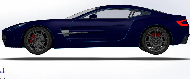
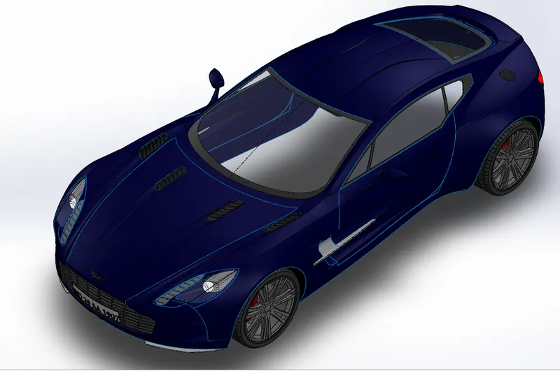
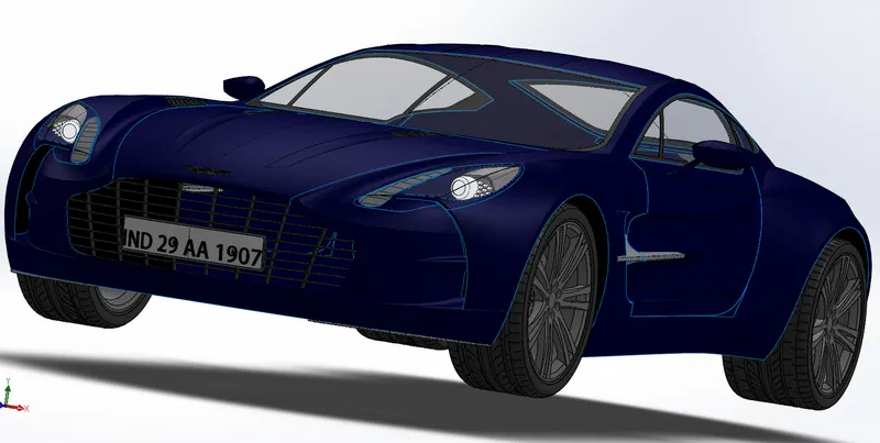
AFTER RENDERING
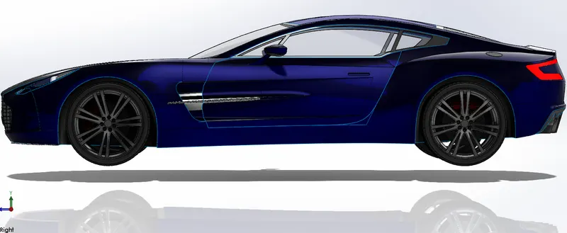
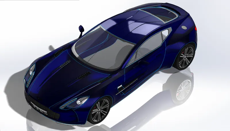
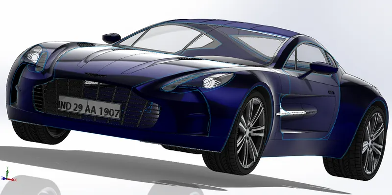
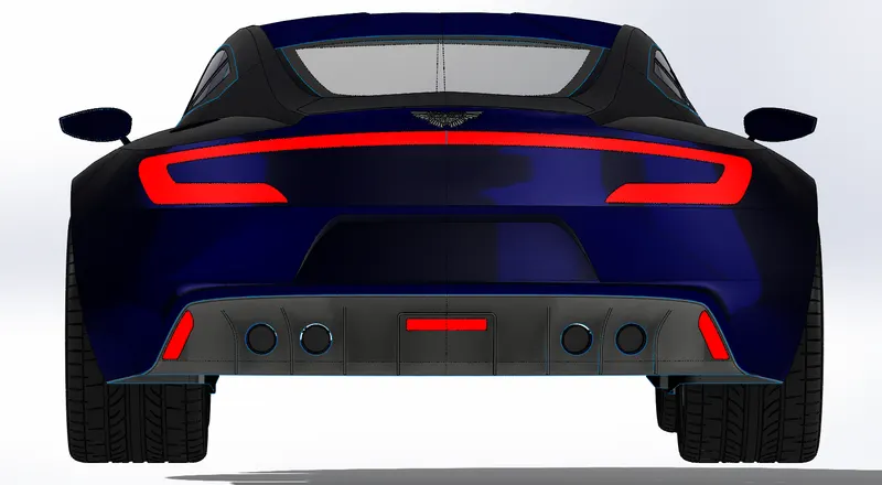
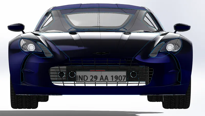
CONCLUSION: IN THE COURSE OF THIS PROJECT WE HAVE SURFACE MODELED ENTIRE ASTON MARTIN ONE-77 CAR AND LEARNT NEW TOOLS AND TECHNIQUES IN SOLIDWORKS.