Fender Design Challenge
FENDER DESIGN
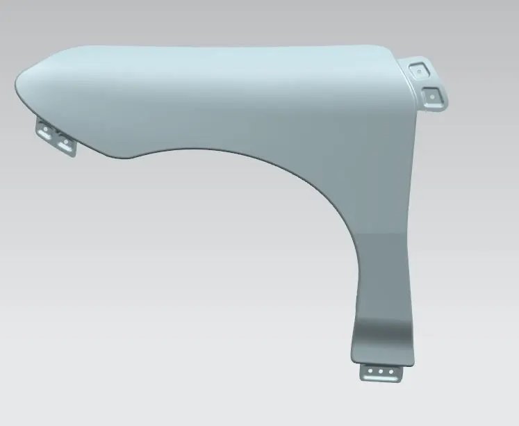
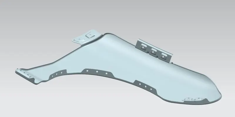
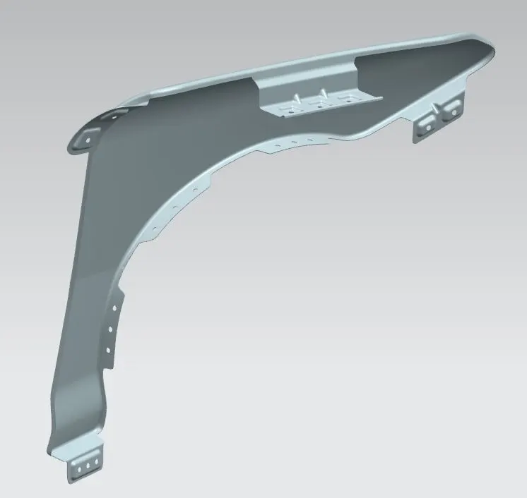
AIM: To create a sheet metal from the given skin of the front fender by designing major mountings on the same according to the master section provided.
THEORY:
FRONT FENDER: It is a part which can be noticed above the wheels of a car. Apart from the aesthetic reasons, its primary function is to protect the engine compartment and the pedestrians from the chips that shoot from the wheel of the vehicle.
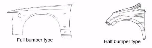
There are two types of fender:
- Full fender type
- Half fender type
Presently we use half fender type because of the following reasons:
- One entire sheet is required for making full fender and so there is a lot of wastage of material in this. But in half fender type we can make two fenders in a single sheet if we increase the area of the sheet a little.
- Half fender type uses less material and hence the performance of the vehicle is better in this type.
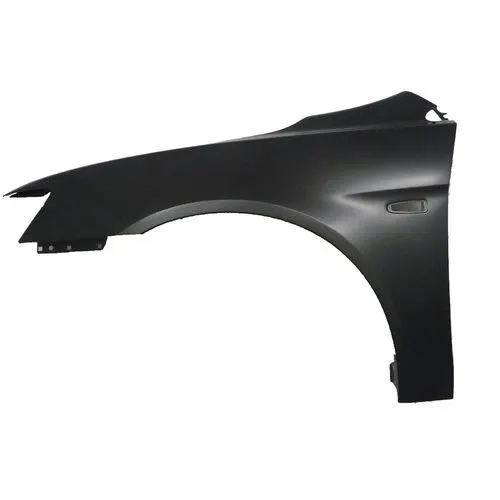
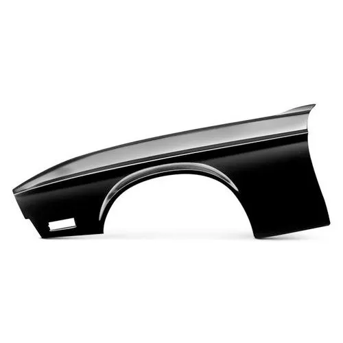
DESIGN CONSIDERATIONS:
While designing the fender the primary thing that a design engineer considers is the minimum gap between the wheel and the wheel arch. It must be in accordance with the regulations for which the vehicle is being designed. If this criterion is met, the curvature of the fender surface is improved.
Once it is approved, the fender is designed to be mounted on the vehicle. The major parts where the front fender is mounted are:
- Bumper: the front part of a car.
- A pillar: the part (pillar) between front windscreen and front door glass which connects up to the roof.
- Sill: it is the part of a cartraditionally running between the wheel-arches beneath the doors.
- Cowl: A cowlis the panel that covers the gap between a car's hood and windshield
- Drip area: it is the area where it gets in the contact with engine compartment.
Most important and critical design rules that we have to follow here is for drip area. A master section is provided according to which we have to proceed to make this area. The values in the master section are obtained from experience and there is always a specific reason for why only this value is considered.
MASTER SECTION
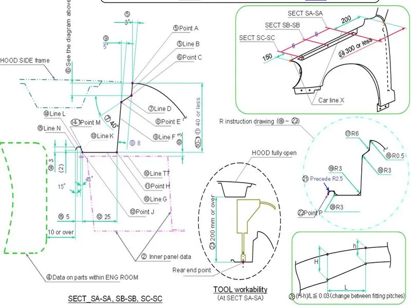
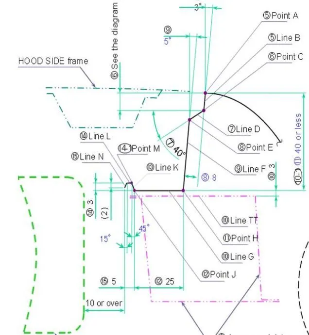
The below image is a part of master section. Here first slant line which is in contact with the fender is at 3deg to the vertical direction. This is because of the production reasons. A straight vertical face is difficult to produce and thus we have to open that sheet a little. This minimum angle of opening is 3deg. Similarly the other line is at 5deg to the vertical, this is for the hiding purpose. This surface will prevent the vision to see the fasteners which are inside. The overall length is 40mm or less, this is because while punching most of the tools are able to work up to 40mm. Also if the depth is more, it will cause the spring back effect.
APPROACH:
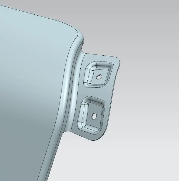
A-PILLAR MOUNTING:
- Make a law extension.
- Create emboss with flat faces for mounting.
DRIP AREA MOUNTING:
- Get the important dimensions from the master section. The length from the cowl region should be 300mm or less and the length from the headlamp region should be 150mm.
- Follow the master section while designing the drip area.
- Make ribs before blending the faces. These ribs strengthen the part.
- Create emboss with flat faces for mounting.
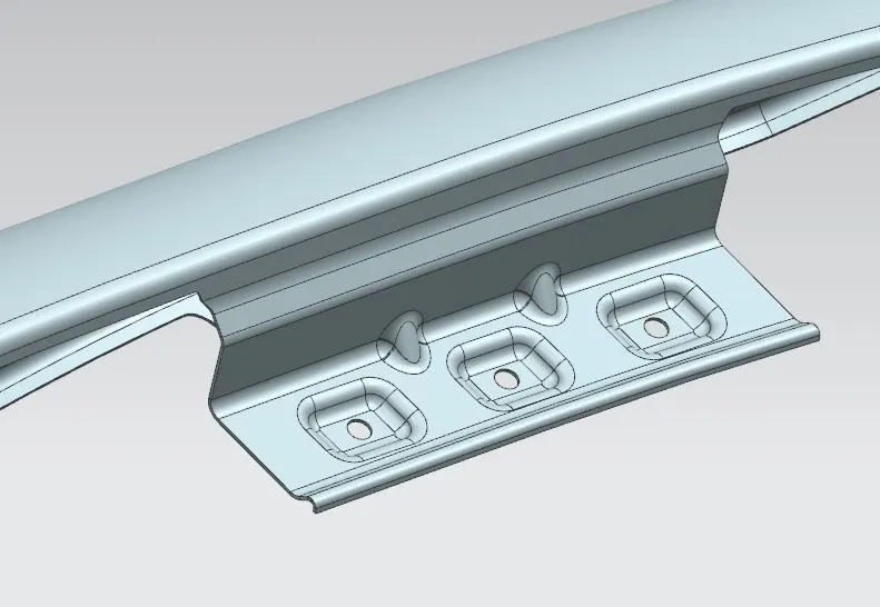
NOTE THAT, the emboss at the end of the drip area (curved part at the end) is to increase the strength of the drip area.
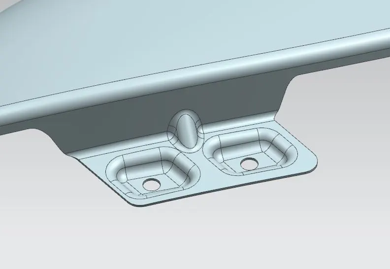
BUMPER MOUTNING:
- Create extension.
- Create emboss with flat face for mounting.
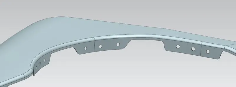
BAFFLE MOUNTING:
This is a plastic part which is used to reduce NVH in a car. This region does not require any extension and can be mounted directly. Thus only approach is to make holes for snap fitting.
SILL MOUNTING:
- We have freedom to create the shape, we can create horizontal law extension or vertical.
- Make emboss with flat face for mounting.
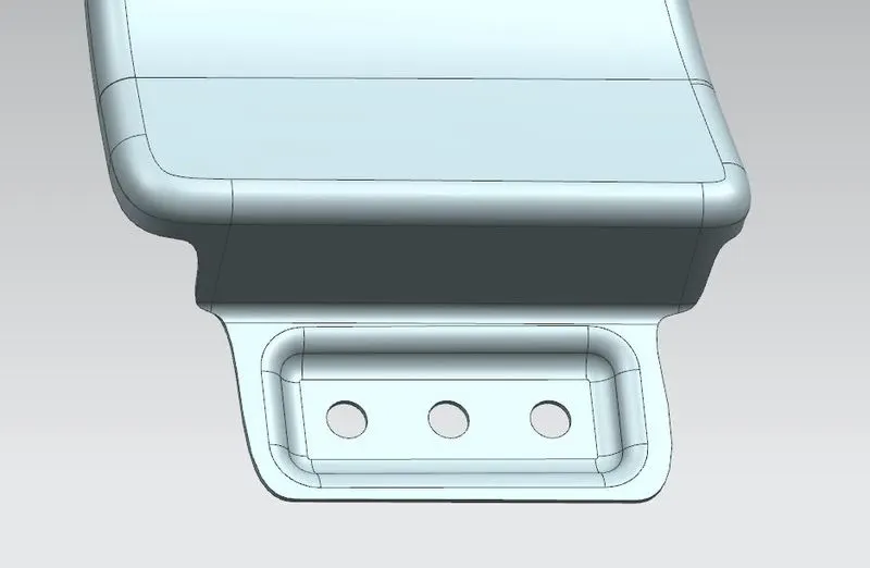
METHOD TO CREATE EMBOSS:
The surface we receive is curved. To mount any other part we need flat face and if we choose the same surface in emboss end cap we will get a curved surface. Thus we have to follow this process to get the flat surface:
- Create a datum plane by choosing 3 points on a face.
- We create a datum plane because obviously any plane is flat.
- We can sketch on this plane (the required shape for emboss).
- Choose emboss option. Choose the sketch, face and datum plane. Specify depth, direction along vector and angle of draft.
- We will get emboss with flat face.\
IMAGES OF THE MODEL