Modelling Spotwelds
OBJECTIVE: The aim of this assignment is to model spot-welds with beam and solid elements in LS-Dyna and run a simulation after defining a proper set-up.
SET-UP:
- The spot-welds should be modeled using beam elements and solid elements separately.
- The axial and shear force should be compared among beam and solid elements.
- The same material card using *MAT_SPOTWELD should be used for both beam and solid elements.
- You can use steel material data for *MAT_SPOTWELD cards and calibrate the failure data according to your results.
- Velocity is considered as 50kmph
PROCEDURE:
Spot-weld with beam elements
Step-1: Importing the .k file into the LS-PrePost interface
- Go to File < Open
- Browse for the provided input file
- Hit open
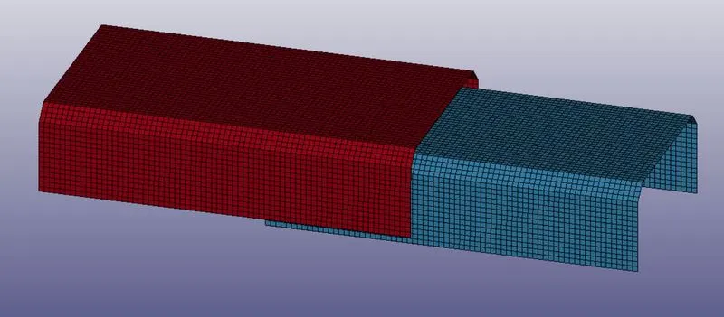
Step-2: Creating beam element
- Go to mesh< element generation< beam
- Select beam by two nodes
- Select two nodes from different parts to create a beam element there
- Repeat the process for the number of beam elements needed
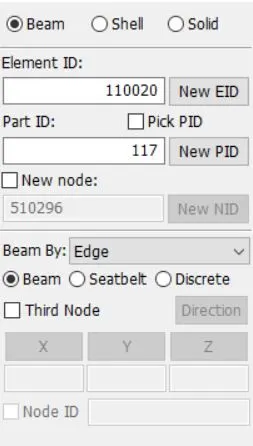
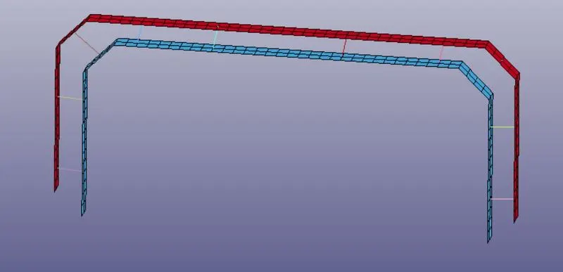
Step-3: organizing
- This step is to delete the section and material that is auto-generated
- Go to keyword manager< model< section and delete all beam section
- Go to keyword manager< model< material and delete all beam material
Step-4: Creating beam section
- Go to Keyword manager< all< section< beam
- Put the beam thickness of around 1mm, Elform 9, CST1
- Hit accept and done
Note: It is necessary to put ELFORM 9 here because the material which we will be using that is spotweld material 100 accepts this formulation for shell elements
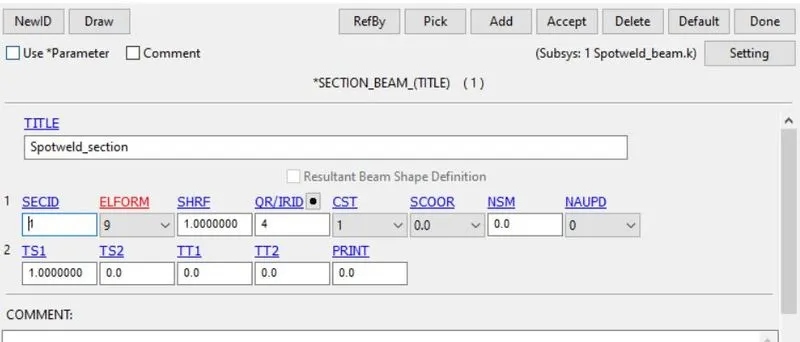
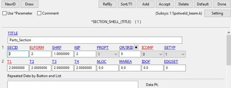
Step-5: Creating Shell section
- Go to Keyword manager< all< section< shell
- Put the shell thickness of around 2mm
- Hit accept and done
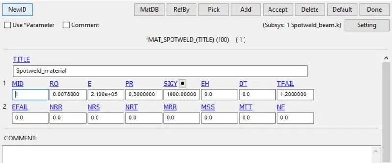
Step-6: Creating Beam material
- Go to Keyword manager< all< material< Material 100
- Enter the steel properties values with very large failure values for forces
- Except, enter time-based failure at around 1.2ms
- Hit accept and done
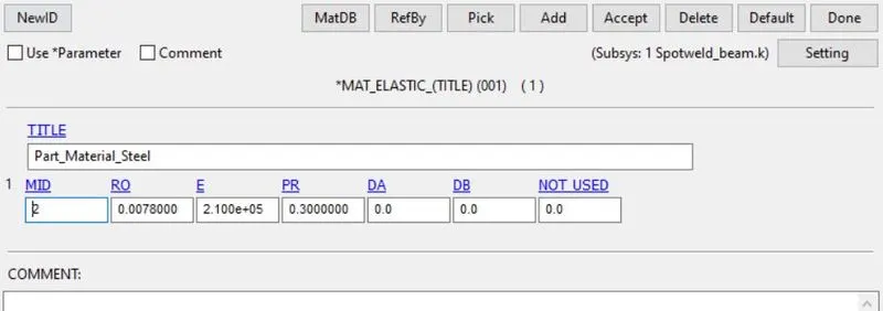
Step-7: Creating Shell material
- Go to Keyword manager< all< Material< Material 001
- Put the steel properties values
- Hit accept and done
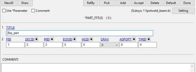
Step-8: Assigning material and sections to the part
- Go to Keyword manager< model< part
- Select the top and bottom parts and assign the section and material created for them
- Then, select spot-weld parts one by one and do the same
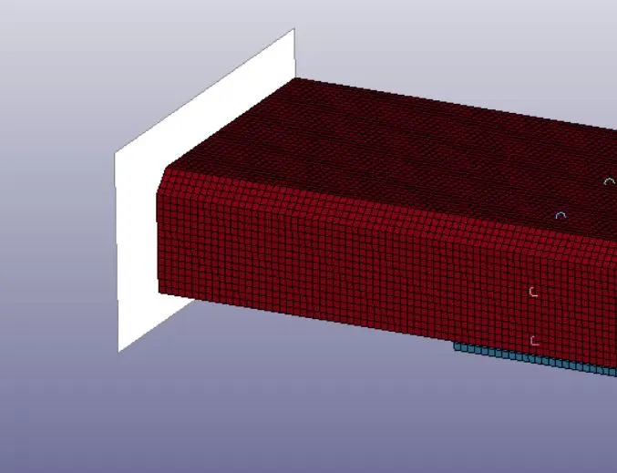
Step-9: Creating rigid wall
- Go to entity creation< Rigid< planer
- Select a node where we want the rigid wall
- Manipulate x-distance to keep some gap between the part and the wall
- Make sure that the wall-normal is opposite the part direction of travel
- Hit apply
Step-10: Giving initial velocity
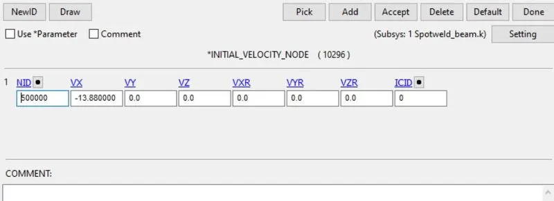
- Go to entity creation< initial< velocity
- Enter 13.88mm/ms according to the direction of travel
- Select all the elements/nodes of the two parts that we want to be moving
- Hit apply
Step-11: Making sets for nodes and parts
- Go to entity creation< set< nodes
- Select all the nodes of the spot welds
- Hit apply
- Similarly, create a set of parts with both the input parts as one
- Hit apply
Step-12: Defining Contact
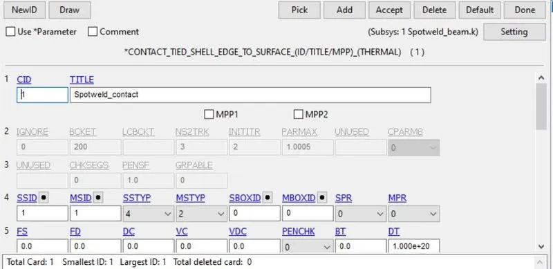
- Go to Keyword manager< all< contact< tied edge to surface
- Select nodes set as slave and part set as Master
- Hit accept and done
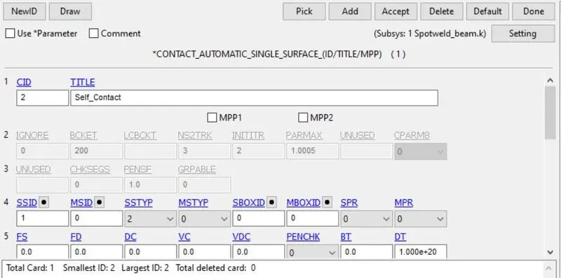
- Again, go to Keyword manager< all< contact< single surface
- Select part set as a slave to define self-contact
- Hit accept and done
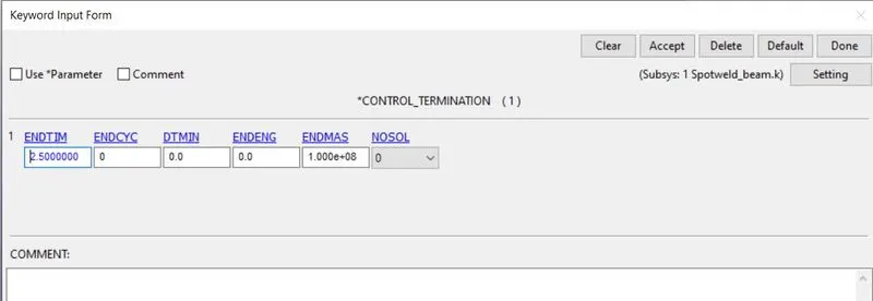
Step-13: Defining control cards
- Go to keyword manager< all< control< termination
- Enter end time as 2.5ms
- Hit accept and enter
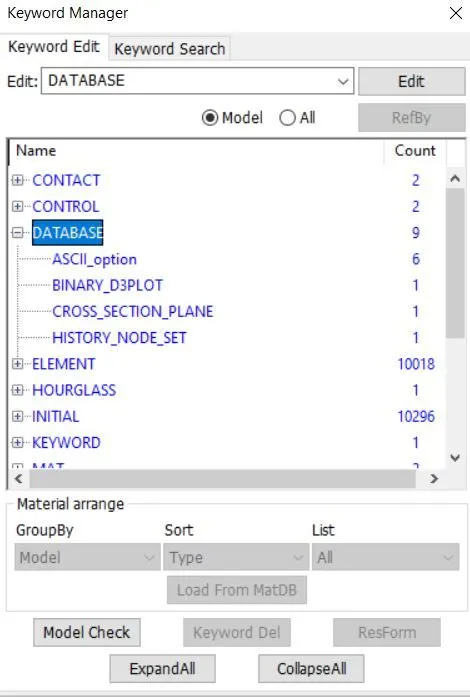
Step-14: defining database cards
- Go to keyword manager< all< database< d3plot
- Define d3plot with dt as 0.1ms
- Hit accept and enter
- Go to keyword manager< all< database< ASCII
- Define GLSTAT, NODOUT, SECFORCE, RWFORC, SWFORCE
- Hit accept and enter
- Go to keyword manager< all< database< history nodes
- Select all the spot-weld nodes
- Hit accept and enter
Step-15: run the analysis
- Save the keyword file
- Open LS-Run and load the saved file
- Run the analysis
Spot-weld with Solid elements
We do not have to set up its model from the scratch. We can use the previously created key file for beam elements and create solid elements in this file. This will save us a lot of time too.
Step-1: load the key file and delete beam elements
- Go to files< open< key file
- Go to keyword manager< model
- Delete parts, section, contact, set of nodes, node history database, and other things related to beam elements
Step-2: Create solid elements
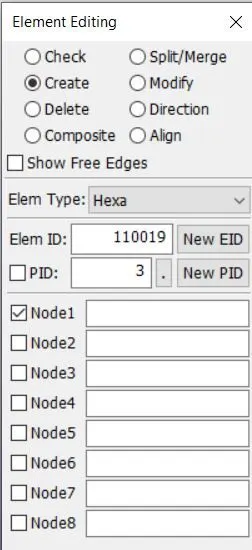
- Go to element tools< element edit< create solid
- We will get an option to select 8 nodes
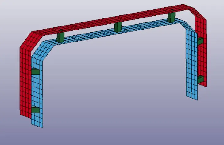
- Select 4 nodes of one element and 4 nodes of other elements in proper and similar order
- Hit accept
Step-3: Create a section
- Go to keyword manager< all< section< solid
- Select ELFORM 1
- Hit accept and done
Step-4: Assign section and material to the part
- Go to keyword manager< model< part
- Select solid part
- Assign section and material to this part
- Hit accept and done
RESULT:
Beam elements:
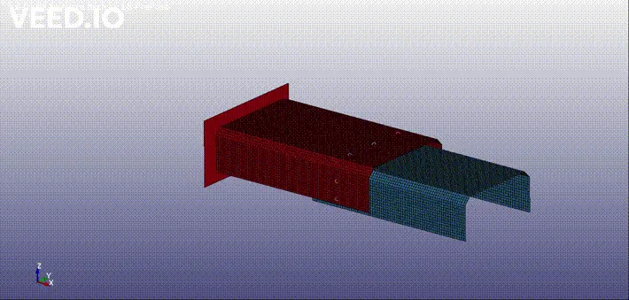
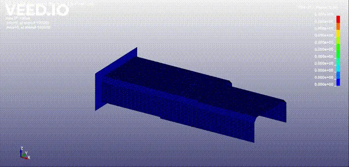
Solid elements:
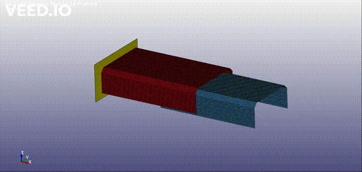
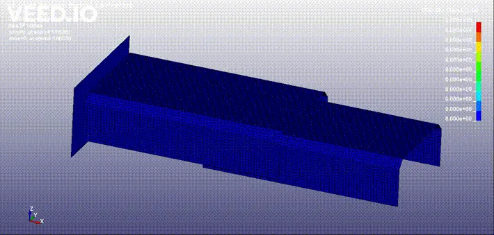
OBSERVATIONS AND GRAPH:
Global data
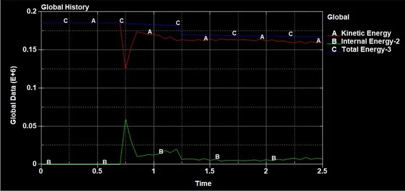
For beam element: From the graph above, we can observe the following things
- Kinetic energy starts from a non-zero value. The initial velocity that we gave to the model explains this value. But, at a time of around 0.7ms, we can observe a drop in the kinetic energy. This is the time when the collision between the part and the wall happens and thus there is a drop in kinetic energy due to the reduction in velocity of the part. The kinetic energy then rises again because the part bounces back and has some velocity.
- There is no internal energy at the start of the simulation because there are no resistive forces in the body. Again, at a time step of around 0.7ms, we can observe a rise in the Internal energy. This is because the resistive forces arise in the body as a result of collision which acts as an external load to the body.
- The kinetic energy is dominant in determining the total energy as the latter’s graph is identical to the former’s graph.
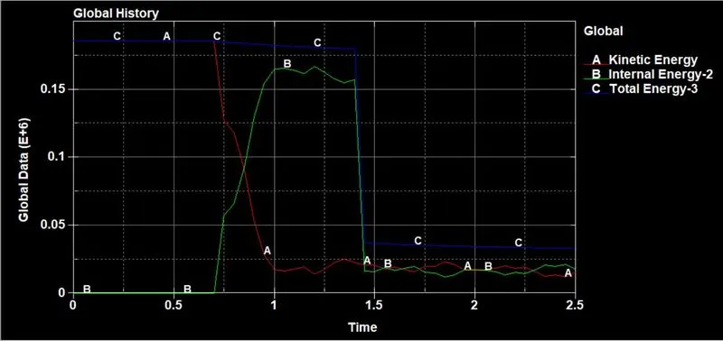
For Solid element: We can observe that there is a lot of difference (listed below) in this global data graph than the beam element graphs.
- The kinetic energy drops by a lot when compared to the beam element graph.
- The Internal energy developed in the part is greater than what developed in the beam elements case.
Velocity
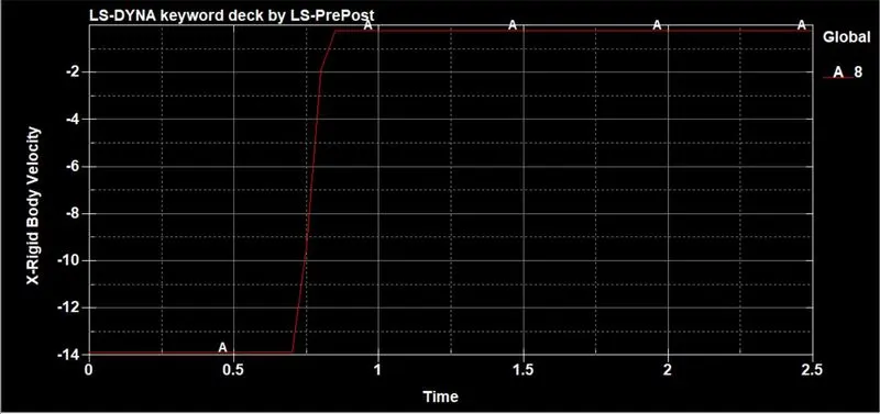
For beam element: We can observe that the velocity rises in the graph. Speaking numerically, this rise actually denotes the fall in the velocity.
- Initially, we can observe a constant velocity which is defined by the user
- After the collision time step, there is a drop in the velocity
- After reaching the lowest value, the velocity is constant again
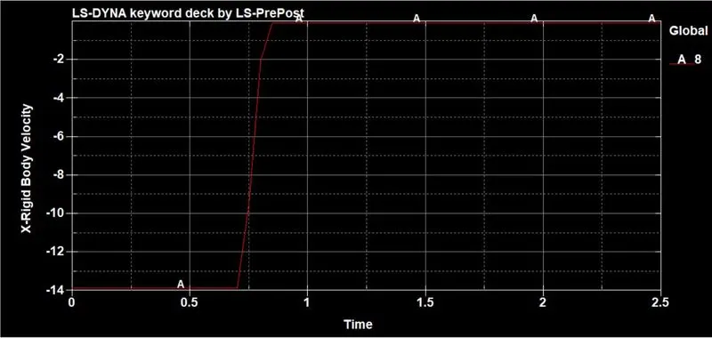
For Solid element: The velocity graph is almost similar to that for the beam element. However, the only difference in this graph is that the velocity drops a litter higher than what we observed in the beam element.
Rigid wall force
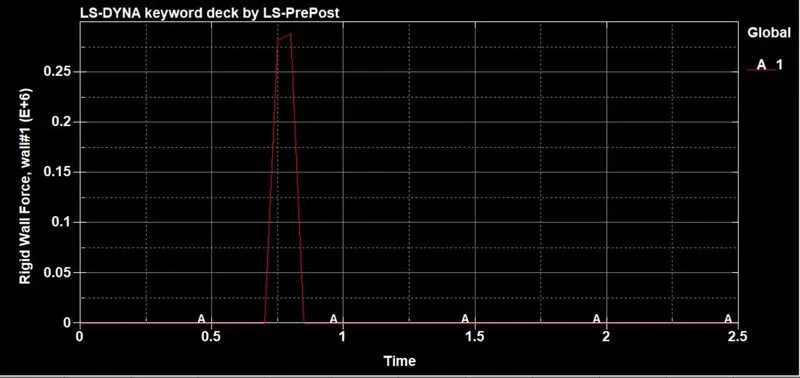
For beam elements: We can see that the rigid wall force is zero initially and in the end. It only fluctuates for a small time step. This is the time when the body collides with the wall thus giving rise to the forces.
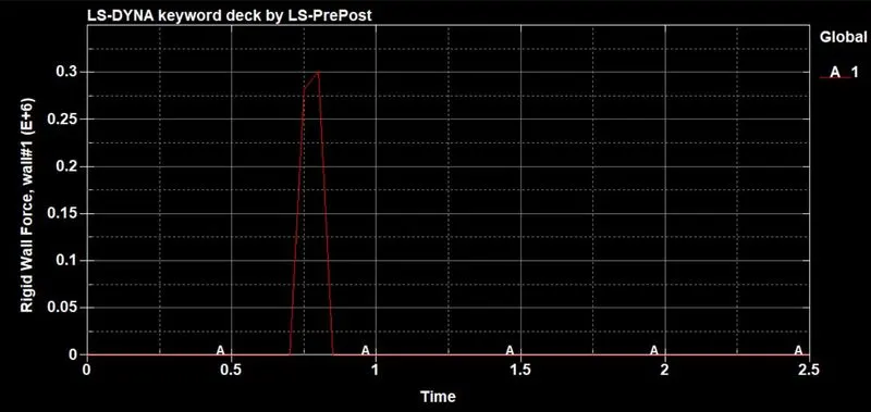
For Solid element: The rigid wall forces graph is also almost similar to that for the beam element. However, the only difference in this graph is that the force generated in the wall is a little higher than what was generated in the beam element case.
Sectional wall forces:
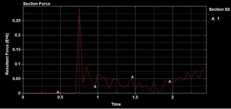
For beam elements: The above graph shows the resultant forces at the defined sectional wall. We can observe the following things from the graphs.
- Forces are zero initially. This is because the elements of the bodies are only moving forward and have no external load acting on them.
- Forces arise after the collision. This is because the collision exerts an opposing force on the body which propagates in the body. The part responds to this by resistive forces which can be seen in the graph.
- The fluctuations in the graph after the collision are due to disturbances in the part.
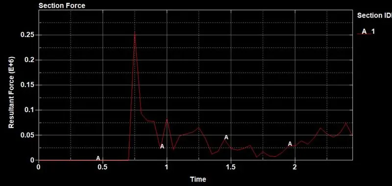
For Solid element: The sectional wall forces graph is also almost similar to that for the beam element. These two graphs are interchangeable up to the time of the collision. However, the fluctuations in both the graphs are different which makes them different.
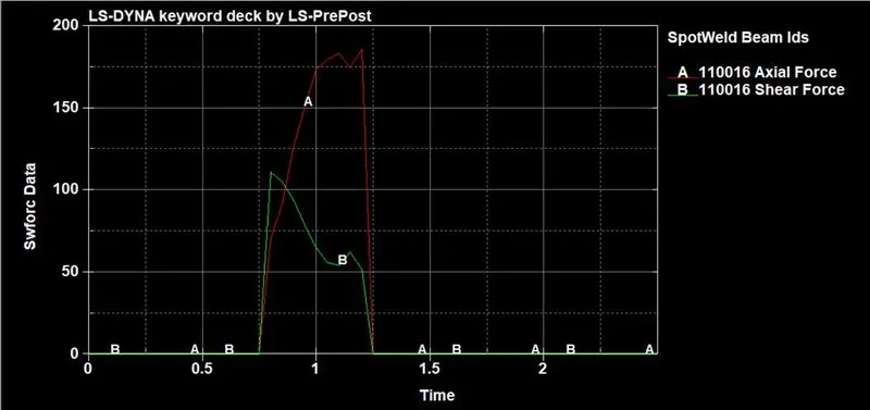
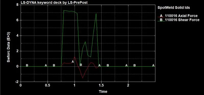
Axial and shear forces
In a beam element:
In a solid element:
CONCLUSION: Through this assignment, I have learned how to model the spot-weld with two different methods and run the simulation.