Usage of Collaborate tool in REVIT
1.
Aim:- Open an architectural template. Using the Manage tab set project base point and project shared coordinates for the project
Introduction:-
- Grids are used to place the columns, beams, footing and It is also used to take a center to center distance between the columns, beams, footing
- Coordinates are the set of values that helps to show exact position of a point in the coordinate plane
Procedure:-
Step1:-
- Open a new project file in the architectural template
- To create the grid lines
- Go to the grids in the architectural tab
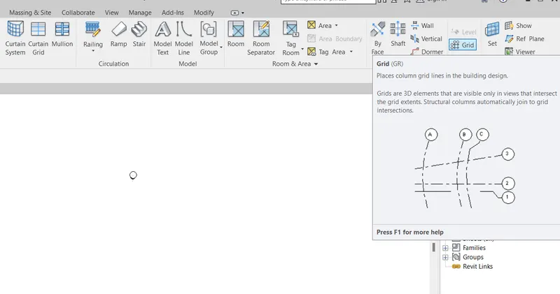
Step2:-
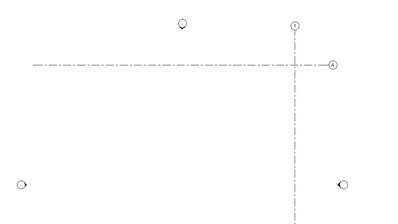
- After selecting the grids then draw the grid lines as shown below
- The transverse grid is in alphabetic
- The longitudinal grid is in numerical
Step3:-
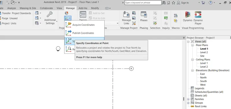
- After creating the grid lines then we have to specify the coordinates for that
- Click on the manage tab then go to the coordinate option then you will get 4 types coordinates
- Then select the specific coordinates at point
Step4:-
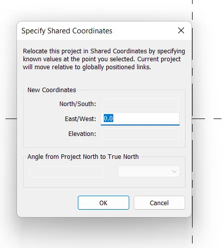
- When we select the specific coordinates at point
- Select the line which you want to add the coordinates
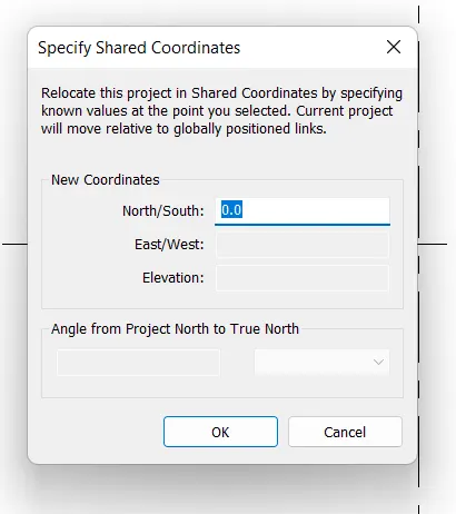
- Then specify shared coordinates dialouge box opens
- Then change the value to 0
Step5:-
- When we select the specific coordinates at point
- Select the line which you want to add the coordinates
- Then specify shared coordinates dialouge box opens
- Then change the value to 0
Step 6:-
- After specifying the values to it then go to visibility graphic command
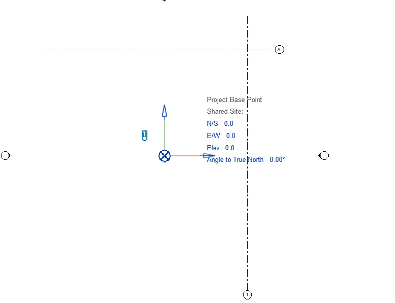
- Then switch on the project base point
- Then change all the values as 0
Result:-
This is the project base point after changing the values to 0
2.
Aim:- Open another new file but with a structural template. Using the manage tab set project parameters the same as the architectural model. Copy the parameters from the architectural model to the structural template or enter the parameters manually into the structural model
Introduction:-
- Grids are used to place the columns, beams, footing and It is also used to take a center to center distance between the columns, beams and footing
- Coordinates are the set of values that helps to show exact position of a point in the coordinate plane
Step1:-
- Open a new project file in the structural template
- To create the grid lines
- Go to the grids in the architectural tab
Step2:-
- After selecting the grids then draw the grid lines as shown below
- The transverse grid is in alphabetic
- The longitudinal grid is in numerical
Step3:-
- After creating the grid lines then we have to specify the coordinates for that
- Click on the manage tab then go to the coordinate option then you will get 4 types coordinates
- Then select the specific coordinates at point
Step4:-
- When we select the specific coordinates at point
- Select the line which you want to add the coordinates
- Then specify shared coordinates dialouge box opens
- Then change the value to 0
Step5:-
- When we select the specific coordinates at point
- Select the line which you want to add the coordinates
- Then specify shared coordinates dialouge box opens
- Then change the value to 0
Step 6:-
- After specifying the values to it then go to visibility graphic command
- Then switch on the project base point
- Then change all the values as 0
Result:-
This is the project base point after changing the values to 0
3.
Aim:- Re-open the architectural model. Using the tools under the Collaborate tab make the architectural model a central model (enabling simultaneous working on the model)
Introduction:-
Central model is a master project file for work shared project.
- The central model stores the current ownership information for all elements in the project
Procedure:-
Step1:-
- Re-open the architectural model
- To make this project file as a central model
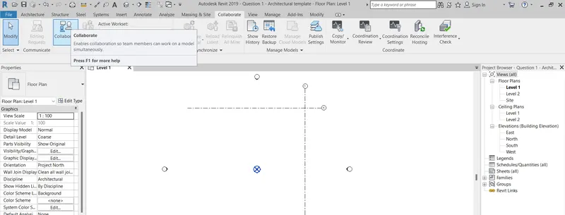
- Click on the collaborate tab then click on the collaborate option
- Then wait some some times for the dialouge box
Step2:-
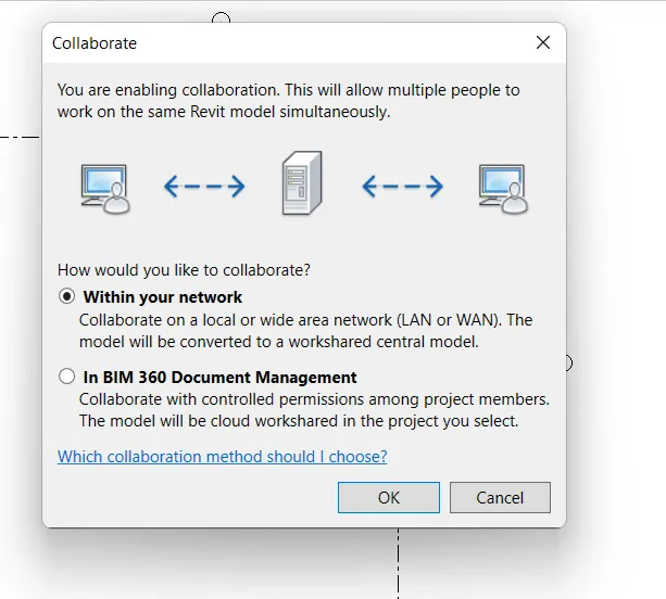
- After selecting the collaborate option the collaborate dialouge box opens
- Then click on the within your network
- Then click on OK
Step3:-
- After completion of the collaborate options
- Then click on the save option
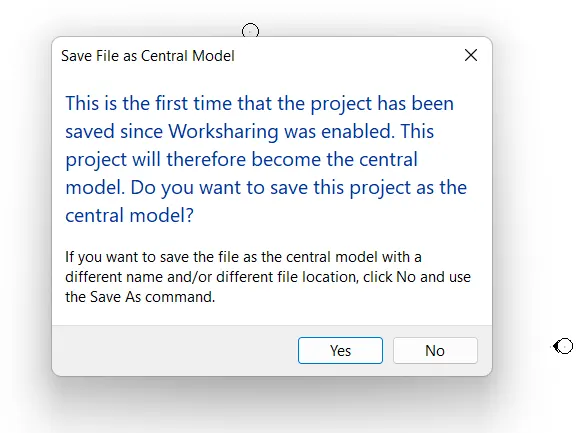
- Then save file as central model dialouge box opens
- Then click on Yes
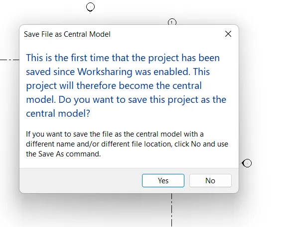
Result:-
This is the project file which is saved as central model
4.
Aim:- Create the Grids Longitudinal and Transverse pattern for the project similar to the task done in Week 2
Introduction:- Grids are used to place the columns, walls and It is also used to take a center to center distance between the columns and walls
Procedure:-
Step1:-
- Open a architectural template saved file
- The transverse and longitudinal grids already placed
- To create the more grid lines
- Go to the offset command
- Take a offset as 3000mm
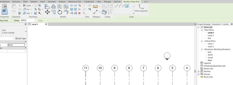
Step2:-
- After taking the offset 300mm then place the cursor on the created grids
- Offets the grids in transverse and longitudinal direction
- The transverse grids is in Alphabetic
- The longitudinal grids is in Numerical
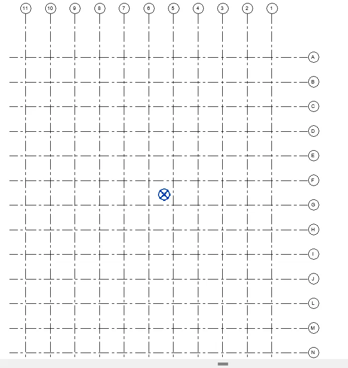
Result:-
This is the transverse and longitudinal grids after taking a 3000mm offset on both the sides
5.
Aim:- Synchronize the changes from the local copy to the central file of the architectural model.
Introduction:- Synchronize with central model tool is used to save your local changes to the central model
- Synchronize option is used when we work in workshared project (workset)
Procedure:-
Step1:-
- Open already saved project file with central model
- To synchronize this project file
- Click on the collaborate
- Next click on the synchronize with central
- Then click on the synchronize and modify settings
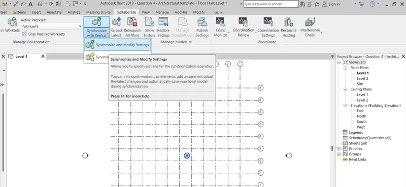
Step2:-
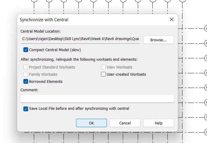
- Then synchronize with cetral dialouge box opens
- Then click on the compact central model
- Then click on OK
Step3:-
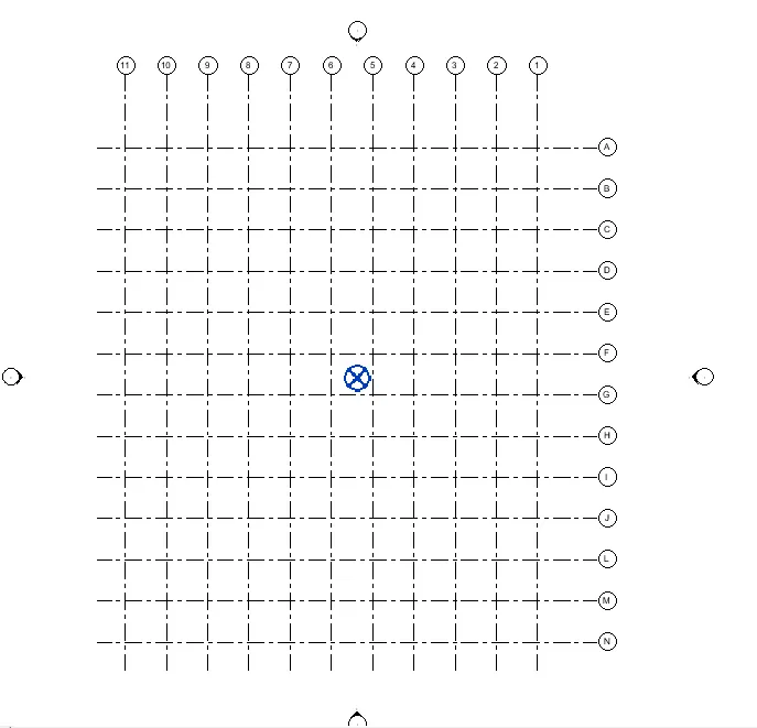
- After clicking OK to the synchronize with central
- Then the project is synchronized with the central model
Result:-
This is the synchronized project with central model
6.
Aim:- Open the structural model and use the collaborate tools to save the model as a central file.
Introduction:- Central model is a master project file for work shared project.
- The central model stores the current ownership information for all elements in the project
Procedure:-
Step1:-
- Re-open the structural model
- To make this project file as a central model
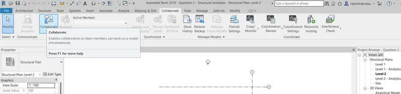
- Click on the collaborate tab then click on the collaborate option
- Then wait some some times for the dialouge box
Step2:-
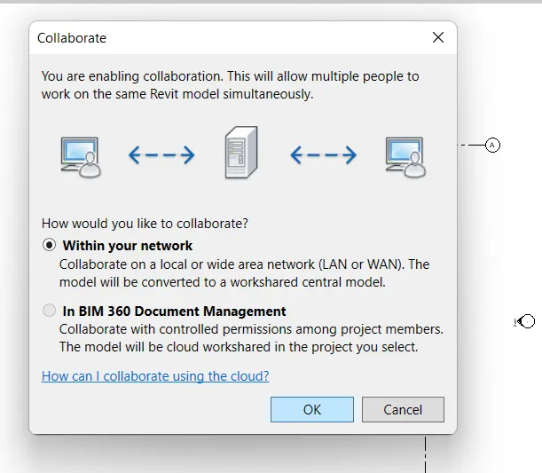
- After selecting the collaborate option the collaborate dialouge box opens
- Then click on the within your network
- Then click on OK
Step3:-
- After completion of the collaborate options
- Then click on the save option
- Then save file as central model dialouge box opens
- Then click on Yes
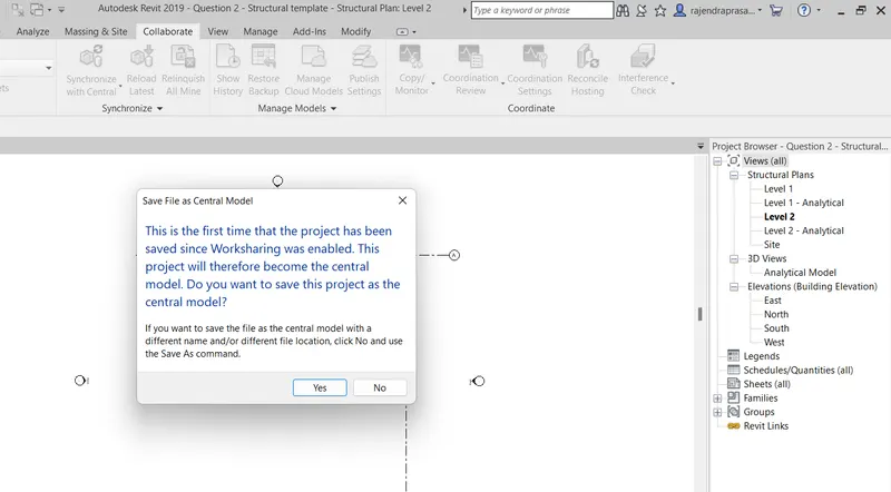
Result:-
This is the project file which is saved as central model
7.
Aim:- Under the Collaborate tab, select the grids and levels from the architectural model, and using Copy Monitor try to copy the grids to the structural model. See what happens when the copy monitored grid is moved around in the structural model
Introduction:- Copy/monitor option is used to copy the linked model into the current project
- This option helps to edit the elements in the linked project
Procedure:-
Step1:-
- Reopne the structural model which you have saved
- To insert/link the Revit file
- Go to insert then click on Link Revit
- Open the architectural model
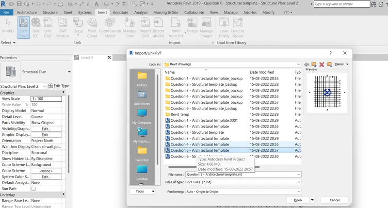
Step2:-
- After that select a copy monitor optionto copy the linked project
- Then select the select link option
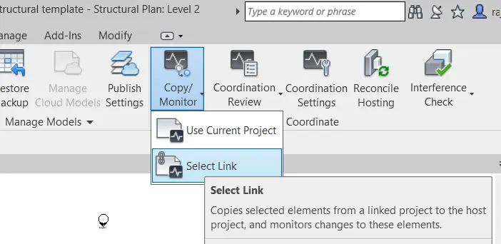
Step3:-
- After selecting the elements
- Click on copy then select the multiple option
- Then select the elements which you want
- Clik on finish near the multiple
- Then go to the modefy option then click on right mark in green colour (Finish)
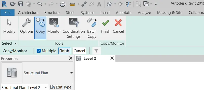
Step4:-
- After make it as a copy
- The combination of architectural and structural model is as shown below
- The transverse grids is in Alphabetic
- The longitudinal grids is in Numerical
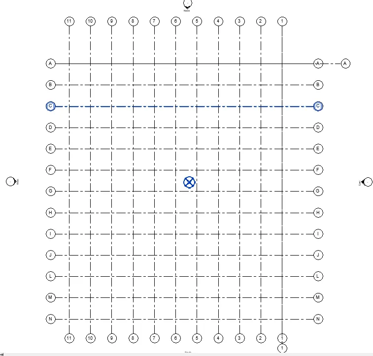
Result:-
The combination of architectural and structural model after using copy/monitor option
8.
Aim:- Create another new file with a construction template. Save the new file as a central model. This file will include both architectural and structural model. Under the manage tab, Click manage links to link both architectural and structural files. Save the file and close all the files.
Introduction:- Central model is a master project file for work shared project.
- The central model stores the current ownership information for all elements in the project
Procedure:-
Step1:-
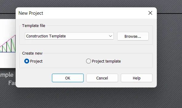
- Open the construction template file
- Click on the project
- Then click on OK
Step2:-
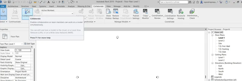
- To make this project file as a central model
- Click on the collaborate tab then click on the collaborate option
- Then wait some some times for the dialouge box
Step2:-
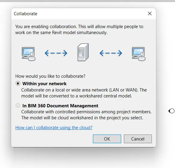
- After selecting the collaborate option the collaborate dialouge box opens
- Then click on the within your network
- Then click on OK
Step3:-
- After completion of the collaborate options
- Then click on the save option
- Then save file as central model dialouge box opens
- Then click on Yes
Step4:-
- After make it as a central model
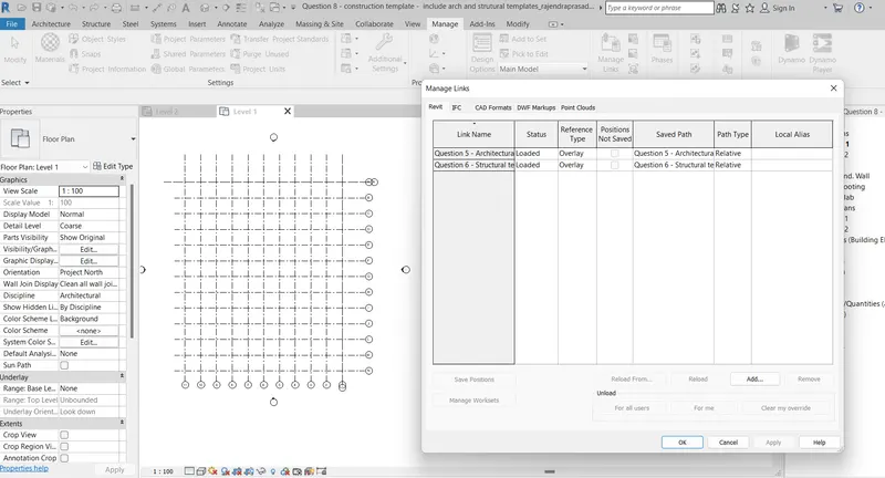
- Link both architectural and structural model into the central model
- Then the grid llines are looks like as shown below
Result:-
This is the linked models to the construction template project file
9.
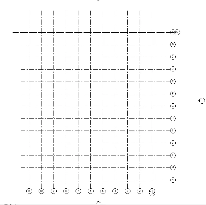
Aim:- Are the grids from structural and architectural model matching in the construction template created? If yes the model is set up for project 2. If not work on the shared parameters and linking options under Manage links
( Hint: origin to origin, by shared coordinates or by project base point to base point ) to link the models in an appropriate manner
- The architectural and structural grids are matching each other
- Yes the model is setup for project 2
10.
Aim:- List a flow chart of a project tree set up in terms of Construction model, Architecture & Structure model, in this exercise and understand how many people can work on the same project using Revit simultaneous
| Construction |
| Architectural model | Structural model |
|
Structural model in general develops the entire frame work of the structure |