Creating 3D Isometric view of various structural elements in AutoCAD
Aim:- To create a 3D Isometric view of various structural element
Introduction:-
Floor Plan
- Floor plan is a type of drawing that shows the layout of a home or property from above
- Planning of a building gives the idea about the building how the building will be done in future
- Planning plays an important role in the civil engineering because without this planning we can't determine structural element
- Planning may be residential, public or commercial building
Section:-
- Its used to see the cross section of the building
Elevation:-
- It's used to see the view of a building in a software before the construction
AutoCAD:-
It is essential to draft the geometry
The different tools required in this drafts are line (L), fillet (F), offset (O), Hatching (H) and Hatch edit (HE), trim (TR), Extrude (EXT), 3D Move (3DM), 3D Orbit (3DO), 3D Rotate (3DROTATE), Subtract (SUB), Solid edit (SOLIDEDIT), Loft (LOFT), Rectangle (REC), Circle (C), Boundary (BO), Render (RR).
Procedure:-
- Go to start menu, click on Start drawing
- Type stratup (Enter) in command line
- Enter the new value of start up:1
- Go to application menu and select new or type new in command line
- In the "create new drawing" dialogue box contains imperial type of systems and metric type of system
- We select the metric system in the "start from scratch" option
- After that in Advance setup option select the decimal unit system in the units
The above procedure should be followed every time when the new sheet is opened
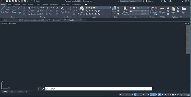
Entering the start up command in the command line
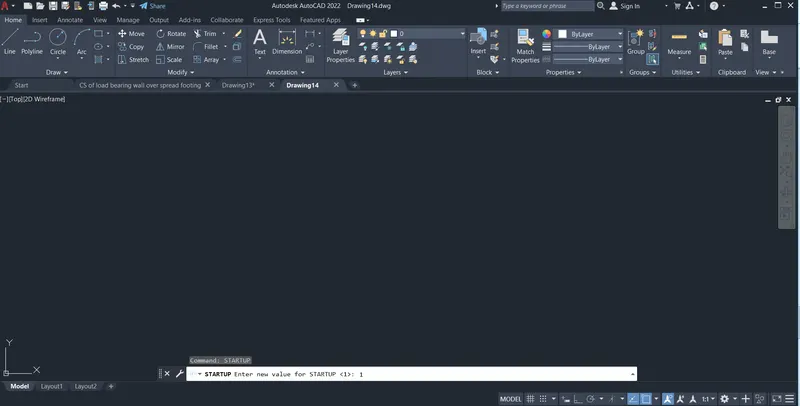
Entering the value 1 for the start up
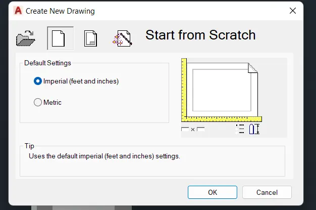
When we go to the new file then we get this file select the metric from start from scratch
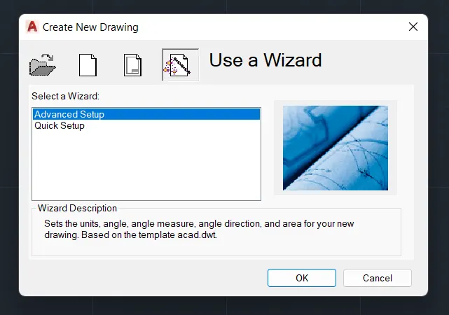
Then advance setup setting should be done by clicking OK
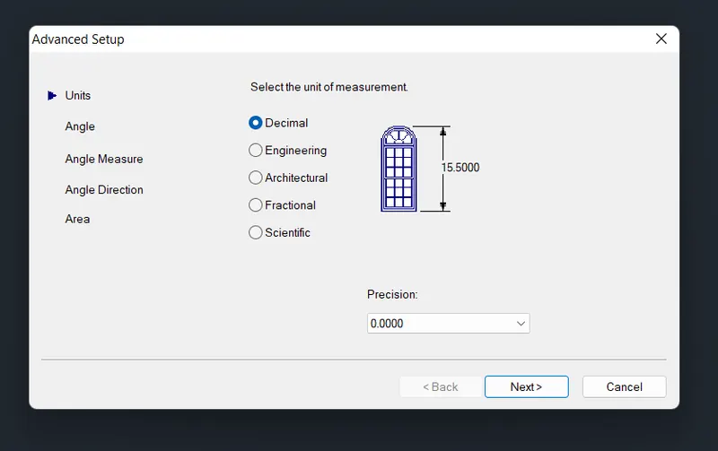
Keep the units in decimal and adjust precision then click next
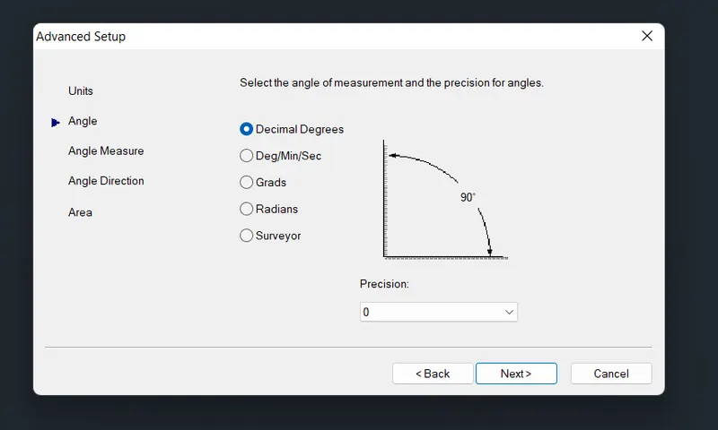
Keep angle in decimal degree and adjust precision then click next
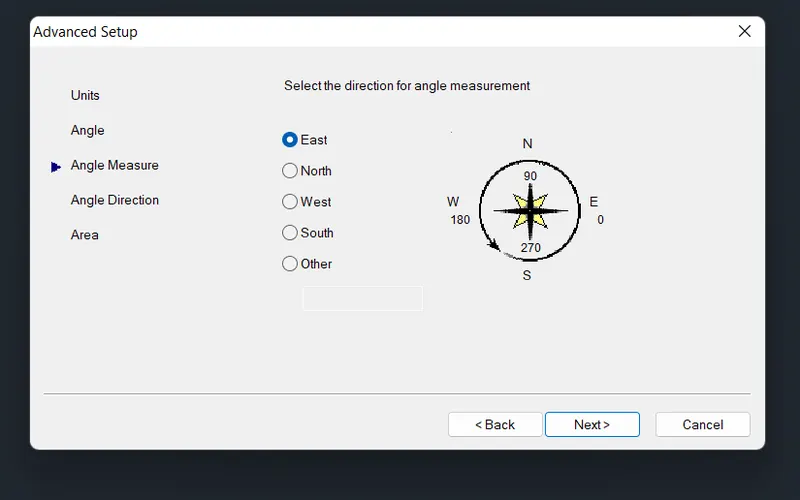
Select the angle measurement in east and click on next
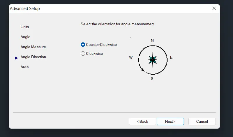
Select angle direction in counter clockwise and click on next
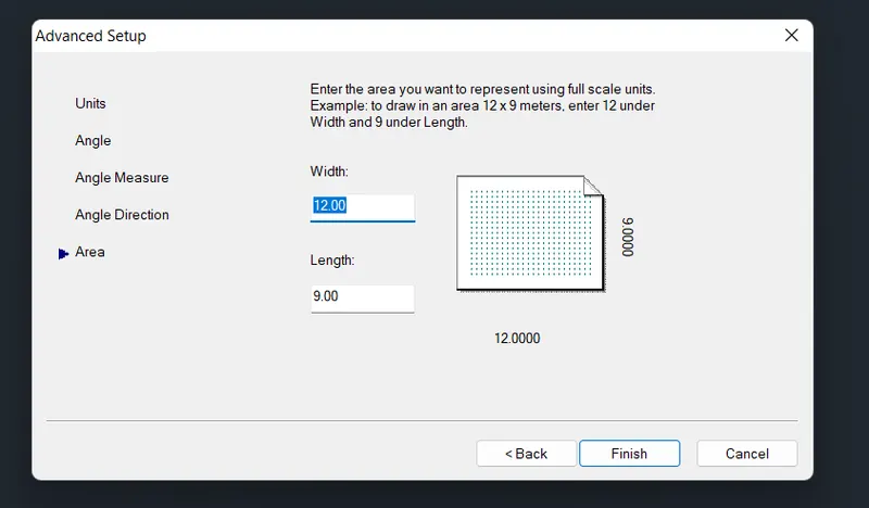
Keep the width as 12m and length of 9m as default and click on finish
Aim:- To draft the 3D Isometric view of a building plan and elevation
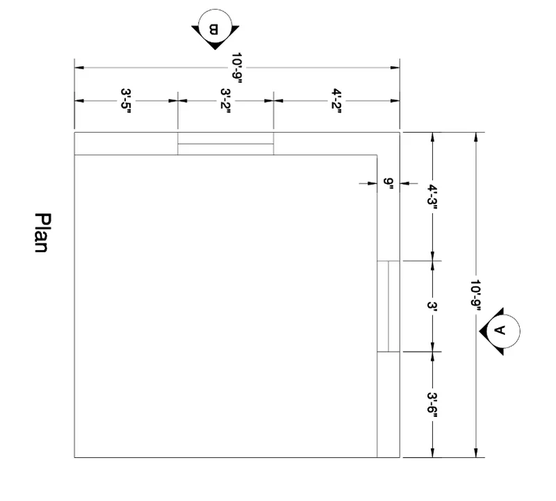
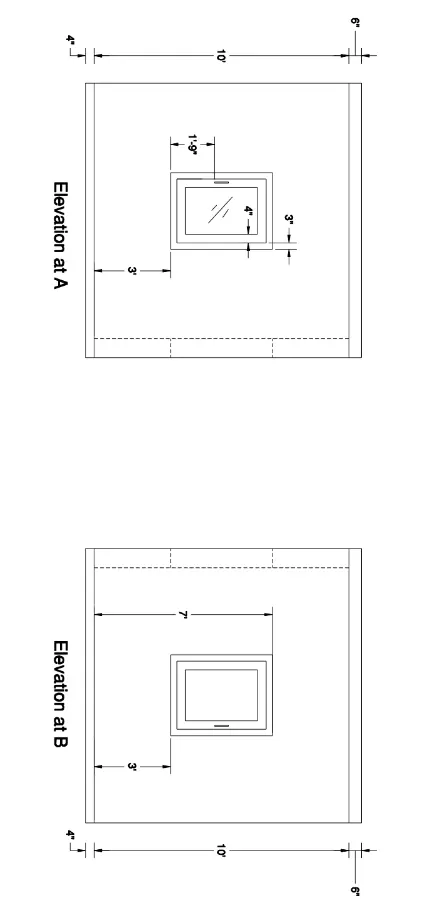
Procedure:-
By using direct distance entry method
- Here all the units are in Imperial (feets and inches)
- Go to 2D wire frame keep the view at top
- Draw a line having a length 10'-9" by using a line command (L) in +ve x- direction
- Again draw a line having a length 10'-9" by using a line command (L) in -ve y-direction
- Take a offset of 9" to from the both 10'-9" +ve x-direction and -ve y-direction line
- Draw a line having length 9" at the left end of the 10'-9" +ve x-direction line in -ve y-direction
- Take a offset of 3'-5", 3'-2" and 4'-2" from the 9" line in +ve x-direction
- Draw a line having length 9" at the bottom end of the 10'-9" -ve y-direction line in -ve x-direction
- Take a offset of 3'-6", 3'-0" and 4'-3" from the 9" line in +ve x-direction
- Here 3'-2" and 3'-0" dimension lines are window portion
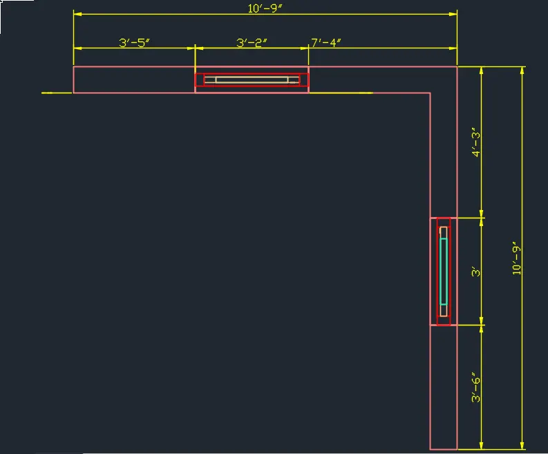
Plan of a building
Elevation
- Take a boundary command (BO) pick up the regions which has to be extrude
- Use a extrude command to extrude the wall upto a height of 10'-0"
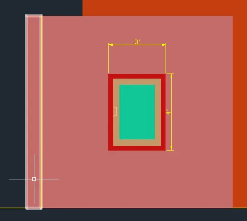
Elevation at A-A
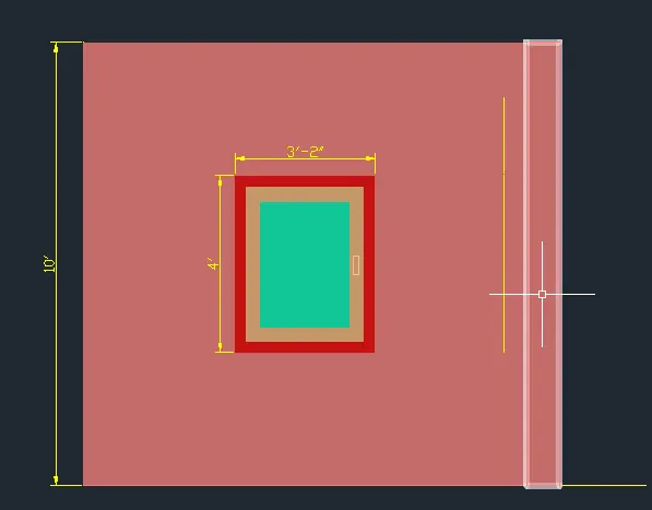
Elevation at B-B
Windows
Window 3'-2"x4'-0"
- Draw a rectangle having a dimension 3'-2"x4'-0" by using a rectangle command (REC)
- Take a offset of 2" inside that rectangle and take offset 3" again from the offseted rectangle 2"
- Use a 3 different layers for Outer frame, mullion and glass
- While taking a extrusion use their respective layers
- Use a extrude command to extrude the Outer frame upto a 4"
- Use a extrude command to extrude the Mullion upto a 2"
- Use a extrude command to extrude the Glass upto a 2"
- Make a 3 copy of the extrude window
- In 1st copy delete the glass and substract the mullion from the outer frame
- In 2nd copy delete outer frame and substract the glass from the mullion
- In 3rd copy delete outer frame, mullion then you will get a glass
- Place these copies properly in order outer frame, mullion and glass
- Place this window properly on the substracted wall
- This is for section B-B
Window 3'-0"x4'-0"
- Draw a rectangle having a dimension 3'-0"x4'-0" by using a rectangle command (REC)
- Take a offset of 2" inside that rectangle and take offset 3" again from the offseted rectangle 2"
- Use a 3 different layers for Outer frame, mullion and glass
- While taking a extrusion use their respective layers
- Use a extrude command to extrude the Outer frame upto a 4"
- Use a extrude command to extrude the Mullion upto a 2"
- Use a extrude command to extrude the Glass upto a 2"
- Make a 3 copy of the extrude window
- In 1st copy delete the glass and substract the mullion from the outer frame
- In 2nd copy delete outer frame and substract the glass from the mullion
- In 3rd copy delete outer frame, mullion then you will get a glass
- Place these copies properly in order outer frame, mullion and glass
- Place this window properly on the substracted wall
- This is for section A-A
Result:-
Elevation at A-A
Elevation at B-B
Aim:- To draft the 3D Isometric view of a building facade plan and elevation
Procedure:-
By using direct distance entry method
- Here all the units are in Imperial (feets and inches)
- Go to 2D wire frame keep the view at top
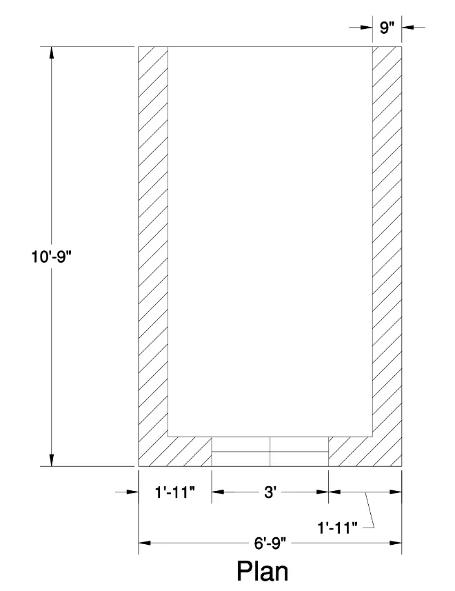
- Draw a line having a length 10'-9" by using a line command (L) in -ve y-direction
- Again draw a line having a length 6'-9" by using a line command (L) in +ve x-direction
- Draw a line having a length 10'-9" by using a line command (L) in +ve y-direction
- Take a offset of 9" to from the both 10'-9" -ve y-direction, 6'-9" +ve x-direction line and 10'-9"in +ve y-direction
- Draw a line having length 9" at the right of the 10'-9" -ve y-direction line in +ve x-direction
- Take a offset of 1'-11", 3'-0" and 1'-11" from the 9" line in +ve x-direction
- Here 3'-0" dimension lines is window portion
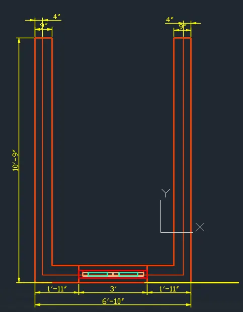
Plan of a building facade
Ground floor
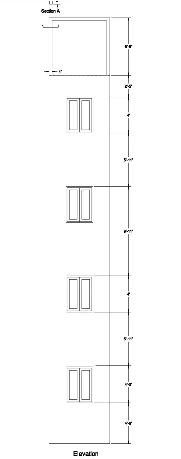
Elevation
- Take a boundary command (BO) pick up the regions which has to be extrude
- Use a extrude command to extrude the wall upto a height of 8'-8" which is upto tip of the window
- Substract the wall which has a window, the window sill level is 4'-6" and height is 4'-2"

Window 3'-0"x4'-2"
- Draw a rectangle having a dimension 3'-0"x4'-2" by using a rectangle command (REC)
- Take a offset of 2" inside that rectangle and take offset 3" again from the offseted rectangle 2"
- Use a 3 different layers for Outer frame, mullion and glass
- While taking a extrusion use their respective layers
- Use a extrude command to extrude the Outer frame upto a 4"
- Use a extrude command to extrude the Mullion upto a 2"
- Use a extrude command to extrude the Glass upto a 2"
- Make a 3 copy of the extrude window
- In 1st copy delete the glass and substract the mullion from the outer frame
- In 2nd copy delete outer frame and substract the glass from the mullion
- In 3rd copy delete outer frame, mullion then you will get a glass
- Place these copies properly in order outer frame, mullion and glass
- Place this window properly on the substracted wall
First floor
Elevation
- Copy elevation from ground floor then change the extrude value
- Substract the wall which has a window, the window sill level is 5'-11" and height is 4'-0" from the upper tip of the Ground floor window
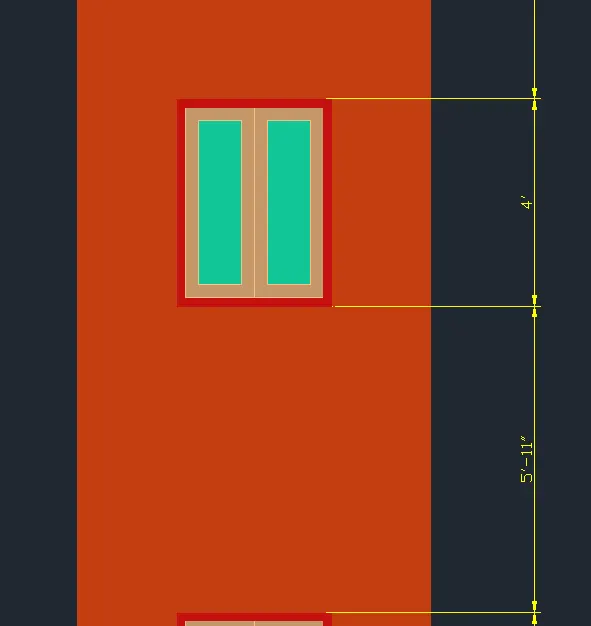
Window 3'-0"x4'-0"
- Draw a rectangle having a dimension 3'-0"x4'-0" by using a rectangle command (REC)
- Take a offset of 2" inside that rectangle and take offset 3" again from the offseted rectangle 2"
- Use a 3 different layers for Outer frame, mullion and glass
- While taking a extrusion use their respective layers
- Use a extrude command to extrude the Outer frame upto a 4"
- Use a extrude command to extrude the Mullion upto a 2"
- Use a extrude command to extrude the Glass upto a 2"
- Make a 3 copy of the extrude window
- In 1st copy delete the glass and substract the mullion from the outer frame
- In 2nd copy delete outer frame and substract the glass from the mullion
- In 3rd copy delete outer frame, mullion then you will get a glass
- Place these copies properly in order outer frame, mullion and glass
- Place this window properly on the substracted wall
Second floor
Elevation
- Copy elevation from first floor
- Substract the wall which has a window, the window sill level is 5'-11" and height is 4'-0" from the upper tip of the First floor window
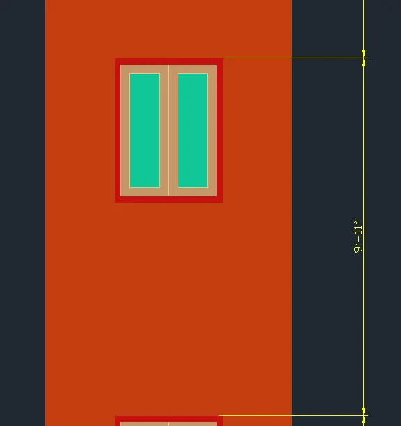
Window 3'-0"x4'-0"
- Draw a rectangle having a dimension 3'-0"x4'-0" by using a rectangle command (REC)
- Take a offset of 2" inside that rectangle and take offset 3" again from the offseted rectangle 2"
- Use a 3 different layers for Outer frame, mullion and glass
- While taking a extrusion use their respective layers
- Use a extrude command to extrude the Outer frame upto a 4"
- Use a extrude command to extrude the Mullion upto a 2"
- Use a extrude command to extrude the Glass upto a 2"
- Make a 3 copy of the extrude window
- In 1st copy delete the glass and substract the mullion from the outer frame
- In 2nd copy delete outer frame and substract the glass from the mullion
- In 3rd copy delete outer frame, mullion then you will get a glass
- Place these copies properly in order outer frame, mullion and glass
- Place this window properly on the substracted wall
Third floor
Elevation
- Copy elevation from Second floor
- Substract the wall which has a window, the window sill level is 5'-11" and height is 4'-0" from the upper tip of the Second floor window
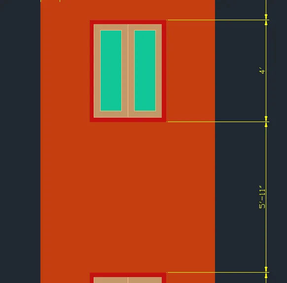
Window 3'-0"x4'-0"
- Draw a rectangle having a dimension 3'-0"x4'-0" by using a rectangle command (REC)
- Take a offset of 2" inside that rectangle and take offset 3" again from the offseted rectangle 2"
- Use a 3 different layers for Outer frame, mullion and glass
- While taking a extrusion use their respective layers
- Use a extrude command to extrude the Outer frame upto a 4"
- Use a extrude command to extrude the Mullion upto a 2"
- Use a extrude command to extrude the Glass upto a 2"
- Make a 3 copy of the extrude window
- In 1st copy delete the glass and substract the mullion from the outer frame
- In 2nd copy delete outer frame and substract the glass from the mullion
- In 3rd copy delete outer frame, mullion then you will get a glass
- Place these copies properly in order outer frame, mullion and glass
- Place this window properly on the substracted wall
Parapet wall
Elevation
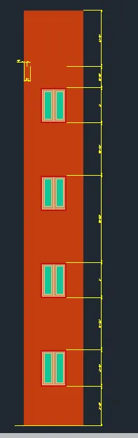
- Copy elevation from Third floor then change the extrude value
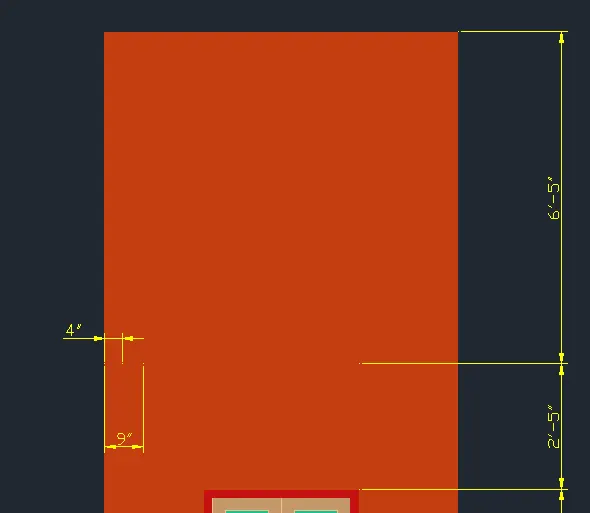
- Here the wall thickness is 9"
- Height of the wall is 2'-5" above the Third floor window in +ve y-direction
- Again copy the 2'-5" wall to upside the heigth of the wall should be 6'-5" in +ve y-direction
- Here the wall thickness 4.5"
Result:-
Aim:- To draft the Isometric 3D view of stairs
Procedure:-
By using direct distance entry method
- Here all the units are in Imperial (feets and inches)
- Go to 2D wire frame keep the view at top
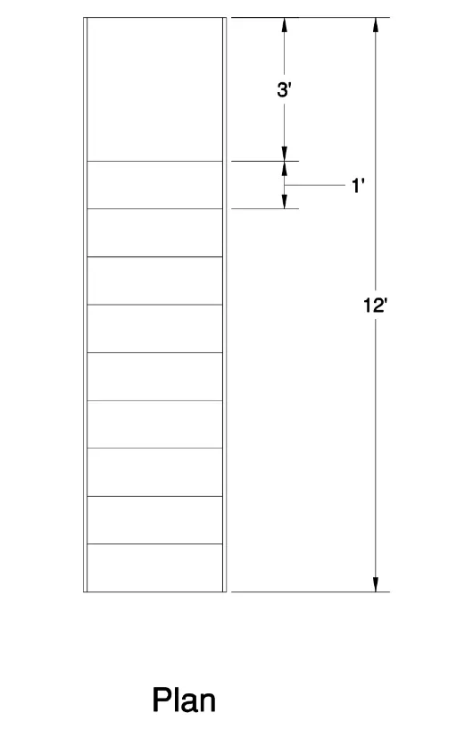
- Draw a rectangle having a dimension 3'x3' by using a rectangle command (REC)
- Explode the rectangle by using a explode command (EX)
- Take a offset of 1' from the exploded rectangle bottom line, the offset should be continue upto 9 times till it reaches the 12' in -ve y-direction
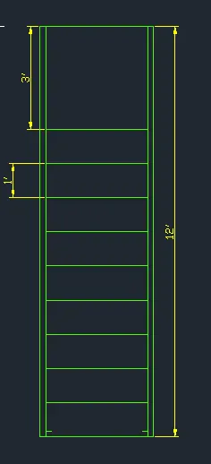
Plan of a stair
Elevation
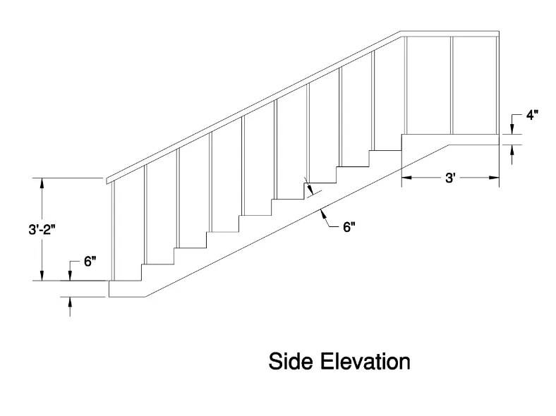
- Take a line command and draw a riser and thread of the stair
- The dimension of the thread is 1' and dimension of the riser is 6"
- There is a 10 riser and 9 thread
- The waist slab having a depth of 4" at the midlanding and depth 6" at the first riser
- Take a boundary command (BO) pick up the regions which has to be extrude
- Use a extrude command to extrude the wall upto a width of 3'-0"
- Draw a rectangle having a dimension 2"x2" for the stair baluster
- Place this baluster at every sides of the thread
- Take a boundary command (BO) pick up the regions which has to be extrude
- Use a extrude command to extrude the wall upto a height of 3'-2"
- Draw a line in the mid point of the every baluster to create a railings
- Draw a rectangle having a dimension 2"x2" for the stair railing
- Use a sweep command to create that railing first click on sweep object then click on the path of the sweep
- Then railings are created at left and right sides
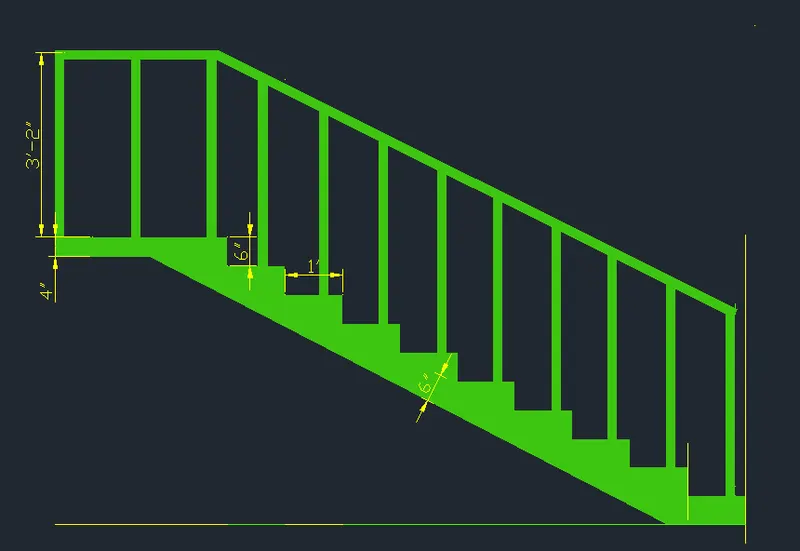
Elevation of a stair
Result:-
Elevation of a stair
Layers used for building plan and elevation, building facade plan and elevation and stairs are
- Building facade - ACI 20
- Dimension - Yellow
- Building view - ACI 11
- Stairs - ACI 80
For window
- Outer frame - Red
- Mullion - ACI 31
- Glass - ACI 120
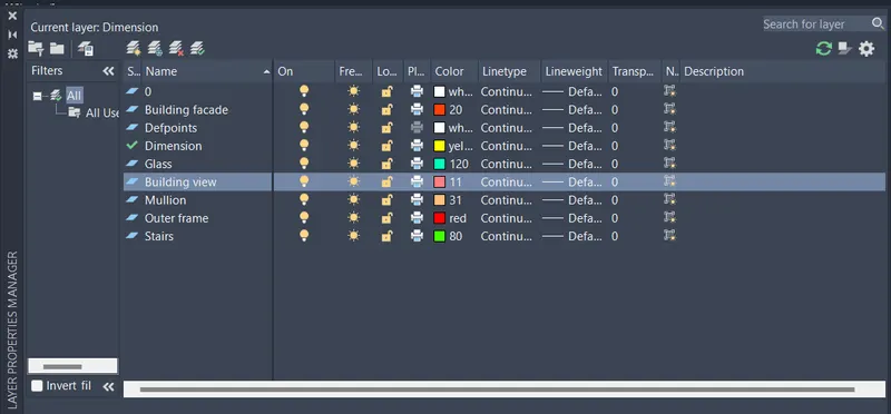
Layers used for building plan and elevation, building facade plan and elevation and stairs
Aim:- To draft the Isometric 3D view of wall spread footing
Procedure:-
By using direct distance entry method
- Here all the units are in metric (millimeters)
- Go to 2D wire frame keep the view at top
- Draw a line having a length 7500mm by using a line command (L)
- Take a offset of 230mm from the 7500mm line
- Draw a line having length of 230mm at the end of the 7500 line and 230mm offseted line
- Take a offset of 100mm, 100mm and 200mm to both left and right side from the 7500 line and 230mm offseted line
- Hatch a wall hatch to the wall which has a 230mm width and Hatch the concrete to the PCC bed
- Take a offset of 3300mm,900mm,3300 from the 230mm line only in the wall portion
- Draw a chejja near the door
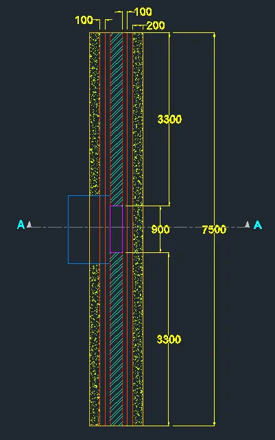
Plan of spread footing
Section:-
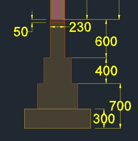
- Draw a line having length 1030mm which is a base in +ve x-direction
- Draw a line having length 300mm in +ve y-direction
- Draw a line having length 1030mm in -ve x-direction
- Draw a line having length 300mm in -ve y-direction
- Draw a line having length 200mm from 1030mm line in -ve x-direction
- Draw a line having length 400mm from 200mm line in +ve y-direction
- Draw a line having length 100mm from 400mm line in -ve x-direction
- Draw a line having length 400mm from 100mm line in +ve y-direction
- Draw a line having length 100mm from 400mm line in -ve x-direction
- Draw a line having length 600mm from 100mm line in +ve y-direction
- Use a mirror command (MI) mirror this half portion to left side in -ve x-direction
- Draw a line having length 230mm from the 600mm line to 600mm line
- Take a offset of 50mm from the 230mm line to +ve y-direction
- Take a offset of 2100mm from the offseted 50mm line in +ve y-direction
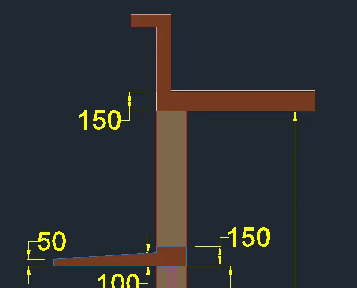
- Take a offset of 150mm from the offseted 2100mm line in +ve y-direction
- Take a offset of 3300mm from the offseted 50mm line in +ve y-direction
- Take a offset of 150mm from the offseted 3300mm line in +ve y-direction
- Take a offset of 590mm from the offseted 150mm line in +ve y-direction
- Draw a line from the 50mm offseted line to slab having length 3300mm in +ve y-direction
- Use a mirror command (MI) mirror this half portion to left side in -ve x-direction
- Take a boundary command (BO) pick up the regions which has to be extrude
- Use a extrude command to extrude that region upto a height of 7500mm
Create a chejja by using a line command L
- Draw a line having 800mm from the 2100mm offseted line in -ve x-direction
- Draw a line having 50mm from the 800mm line in +ve y-direction
- Take a offset of 100mm from the 800mm line then join the 50mm line and offseted 100mm line
- Take a boundary command (BO) pick up the regions which has to be extrude
- Use a extrude command to extrude that region upto a height of 7500mm
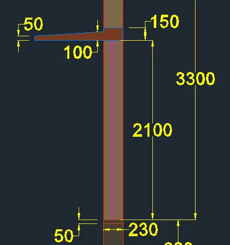
Create a door
- Draw a mid line inside the 2100mm region
- Take a offset of 20mm left side and right side in +ve x-direction and -ve x-direction
- Take a boundary command (BO) pick up the regions which has to be extrude
- Use a extrude command to extrude that region upto a height of 7500mm
Create a parapet wall
- Draw a line having a distance 509mm in +ve y-direction
- Draw a line having a distance 100mm from the 509mm line in -ve x-direction
- Take a offset of 115mm from the 509mm line in +ve x-direction
- Join the lines
- Take a boundary command (BO) pick up the regions which has to be extrude
- Use a extrude command to extrude that region upto a height of 7500mm
At last section is like
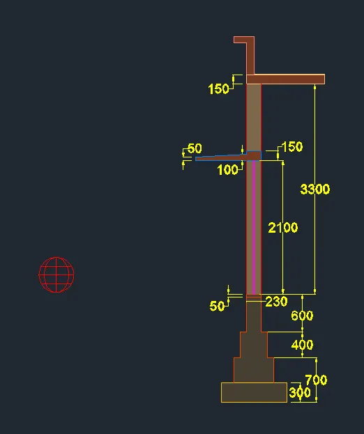
Section
Hatch a wall hatch to the wall which has a 230mm width and Hatch the concrete to the PCC bed
Materials and layers
Use a materials and layers for the section
- PCC - Exposed aggregate fine - ACI 40
- Foundation - Exposed aggregate fine - ACI 20
- 3D Wall - Brindle -Red
- Door - Yellow pine wood - Magenta
- Lintel - Sienna - ACI 150
- Slab - Sienna - ACI 31
- Parapet wall - Sienna - ACI 11
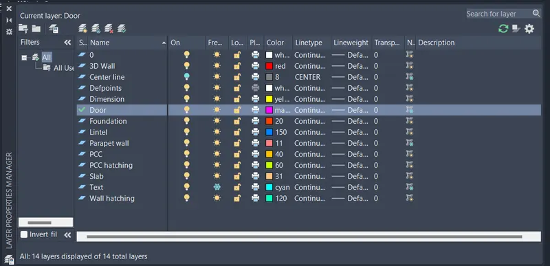
Layers for spread footing
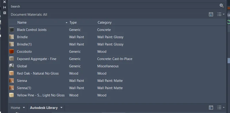
Materials for spread footing
After applying all the materials
- The web light is inserted here which has a intensity 80,000Cd and the filtered colour is 252,253,226
- Light is targeted to door
- Target X,Y and Z axis is 50075mm, 2000mm, -24337mm respectively
- Take a rendered view of a section by using a command RR
- Save the view in jpge formate
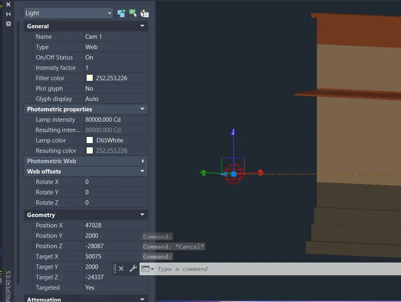
Light used for rendring
Result:-
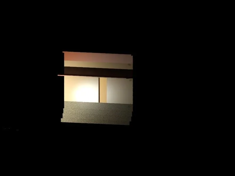
Rendred view of a section in side view
The drawing file for all these drawings are mentioned below