Creation of Multiple viewports, Scaling the drawing and setting in Template in AutoCad
Aim:- To create the multiple view ports, scaling the drawing and setting in template by using AutoCAD
Introduction:-
- View prots allow you to create different views of the object in your model space and display them on the printed page from different scales
- Scaling is essential in the autocad it is used to set the scale of the drawing to fit in the respective printing pages
- Templates includes the all the information in the drawings like name of the architect, name of the client, grade of the concrete, location and date
AutoCAD:-
It is essential to draft the geometry
The different tools required in this drafts are construction line (XL), text(MTEXT), fillet (F), offset (O), Hatching (H) and Hatch edit (HE) block (B), trim (TR).
The commands used for view port and plots are
- Multiple view ports -MV
- Model space -MS
- Paper space -PS
- Print -Cntrl+P
Aim:-Create a multiple view ports for a created Plan and Elevation drawings
Procedure:-
- Open a drawing of a Plan and Elevation drawings in AutoCAD which is in the model
- Click a right buttom of your mouse on the layout
- Select the option from the templates
- Click on a tutorial m-Arch template which has a unit in millimeter or meters
- Our drawings is in millimeter so select the m-Arch template
- Click on the open
- Click on ISO A1 layout then click on OK
- Then the default page setup opens
- Click a right buttom of your mouse on the ISO A1 layout
- Go to page setup manager then click on modify button
- Change the name of the printer to DWG To PDF.pc3
- Check the paper size it should be in ISO A1
- Change the plot area to window and click on the center the plot
- Change the plot style table to monochrome.ctb
- Make sure the drawing orientation is in landscape
- click on OK then close it
- Divide that region into 2 parts by using a line command (L)beacuse 2drawings are needs to place there
- Take multiple view port command (MV) and draw a window in which the drawings are set into that area
- After drawing the window use a model space to enter into the drawing
- Use a scale which is at right side in the status bar, adjust the scale to fit the drawing in that area
- After scaling use paper space command (PS) to exit from the model space here if you zoom out or zoom in the paper will take a zoom option and the scale is not affeted by it
- To lock the multiple view ports take a command miltiple view port (MV)
- Take a lock option and select a on then the view port will lock so that it helps to aviod the changing of scale
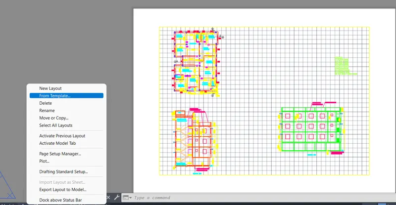
Selection of template from the templates
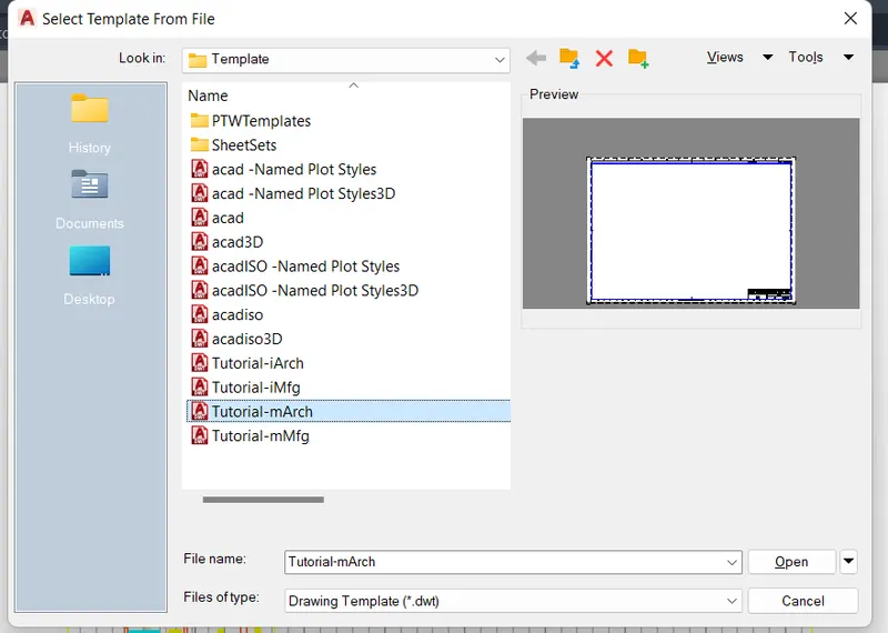
Select a Tutorial m-Arch template which is in metric
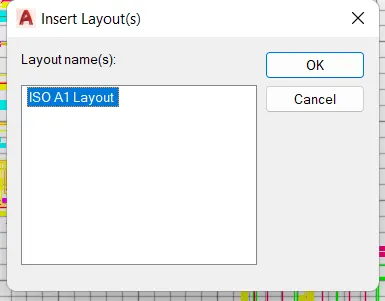
Select a ISO A1 Layout then click on OK
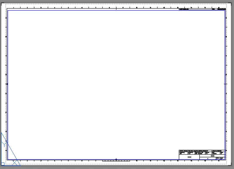
This is the default template of Tutorial m-Arch
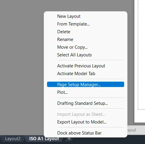
Select the page set up manager in ISO A1 layout to fit the darwing in that paper size
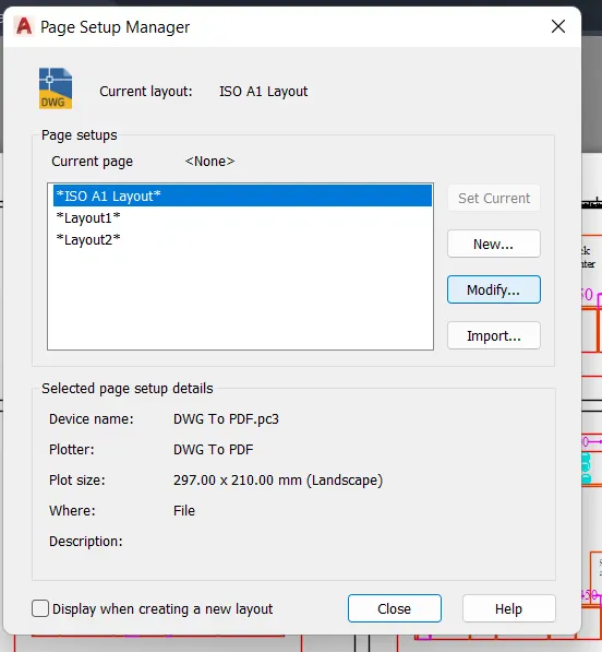
Click on modify to change the size and type of the paper size
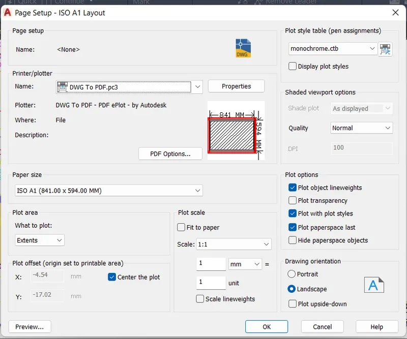
Change the printer, paper size, plot area and other what is required to set the drawings in that area and click on OK then close the tab
Result:-
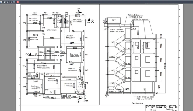
This is the preview of the plan and elevation of a building
Aim:-Create a multiple view ports for a created kitchen layout drawing
Procedure:-
- Open a drawing of a kitchen layout drawing in AutoCAD which is in the model
- Click a right buttom of your mouse on the layout
- Select the option from the templates
- Click on a tutorial m-Arch template which has a unit in millimeter or meters
- Our drawings is in millimeter so select the m-Arch template
- Click on the open
- Click on ISO A1 layout then click on OK
- Then the default page setup opens
- Here delete the view port which is in the blue line
- Click a right buttom of your mouse on the ISO A1 layout
- Go to page setup manager then click on modify button
- Change the name of the printer to DWG To PDF.pc3
- Check the paper size it should be in ISO A4 (297mmx210mm)
- Change the plot area to window and click on the center the plot and fit to paper
- Change the plot style table to monochrome.ctb
- Make sure the drawing orientation is in landscape
- click on OK then close it
- Divide that region into 4 parts by using a line command (L)beacuse 4 drawings are needs to place there
- Take multiple view port command (MV) and draw a window in which the drawings are set into that area
- After drawing the window use a model space to enter into the drawing
- Use a scale which is at right side in the status bar, adjust the scale to fit the drawings in that area
- After scaling use paper space command (PS) to exit from the model space here if you zoom out or zoom in the paper will take a zoom option and the scale is not affeted by it
- To lock the multiple view ports take a command miltiple view port (MV)
- Take a lock option and select a on then the view port will lock so that it helps to aviod the changing of scale
Selection of template from the templates
Select a Tutorial m-Arch template which is in metric
Select a ISO A1 Layout then click on OK
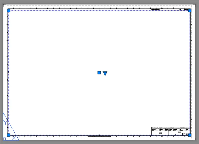
This is the default template of Tutorial m-Arch delete the blue line which is a default view port
Select the page set up manager in ISO A1 layout to fit the darwing in that paper size
Click on modify to change the size and type of the paper size
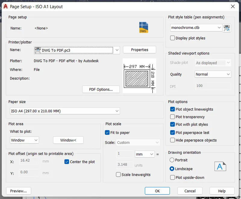 Change the printer, paper size, plot area and other what is required to set the drawings in that area and click on OK then close the tab
Use a plot option to take the preview of the drawings
Result:-
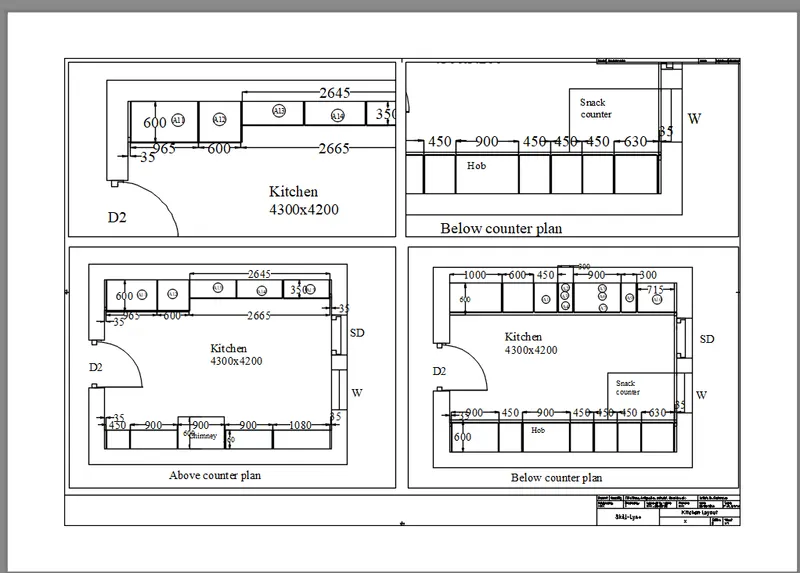
This is the preview of the kitchen layout in A4 size sheet
Aim:-Create a multiple view ports for a created Section of industrial building drawing
Procedure:-
- Open a drawing of a Section of industrial building drawing in AutoCAD which is in the model
- Click a right buttom of your mouse on the layout
- Select the option from the templates
- Click on a tutorial m-Arch template which has a unit in millimeter or meters
- Our drawings is in millimeter so select the m-Arch template
- Click on the open
- Click on ISO A1 layout then click on OK
- Then the default page setup opens
- Here delete the view port which is in the blue line
- Click a right buttom of your mouse on the ISO A1 layout
- Go to page setup manager then click on modify button
- Change the name of the printer to DWG To PDF.pc3
- Check the paper size it should be in ISO A4 (297mmx210mm)
- Change the plot area to window and click on the center the plot and fit to paper
- Change the plot style table to monochrome.ctb
- Make sure the drawing orientation is in landscape
- click on OK then close it
- Divide that region into 3 parts by using a line command (L)beacuse 3 drawings are needs to place there
- Take multiple view port command (MV) and draw a window in which the drawings are set into that area
- After drawing the window use a model space to enter into the drawing
- Use a scale which is at right side in the status bar, adjust the scale to fit the drawings in that area
- After scaling use paper space command (PS) to exit from the model space here if you zoom out or zoom in the paper will take a zoom option and the scale is not affeted by it
- To lock the multiple view ports take a command miltiple view port (MV)
- Take a lock option and select a on then the view port will lock so that it helps to aviod the changing of scale
Selection of template from the templates
Select a Tutorial m-Arch template which is in metric
Select a ISO A1 Layout then click on OK
This is the default template of Tutorial m-Arch delete the blue line which is a default view port
Select the page set up manager in ISO A1 layout to fit the darwing in that paper size
Click on modify to change the size and type of the paper size
Change the printer, paper size, plot area and other what is required to set the drawings in that area and click on OK then close the tab
Use a plot option to take the preview of the drawings
Results:-
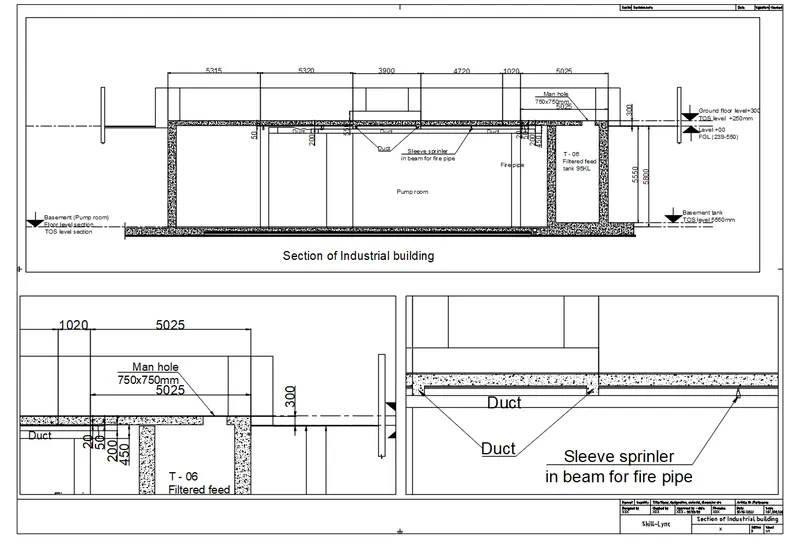
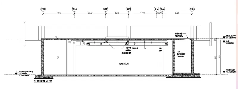
This is the preview of the industrial section drawing in A4 size sheet