Analysis & Design of RCC shear walls in the model using ETABS
Aim:- Analysis and design of RCC shear wall in the model by using ETABS
Introduction:-
- The wall which can carry havy lateral loads are called shear walls
- Shear walls are mandatory in the zone 4 and zone 5 regions because it resists the earthquake loads
- It will helps to avoid the sudden failure of the structure
Procedure:-
Step1:-
- This model is given in the question itself download the model
- Then open the model in the ETABS software
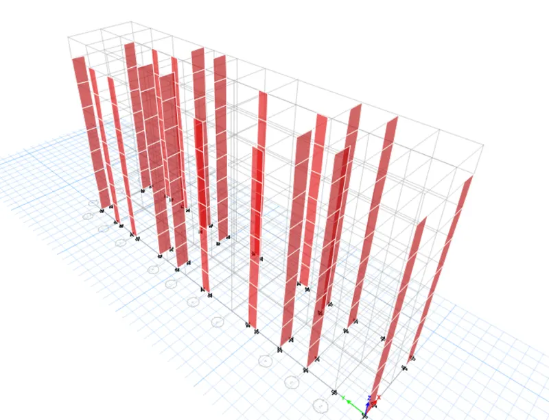
- Then the shear walls are appear like this
Step2:-
- Next make sure that the story are in all sories
- Click on the floor plan which is in the terrace
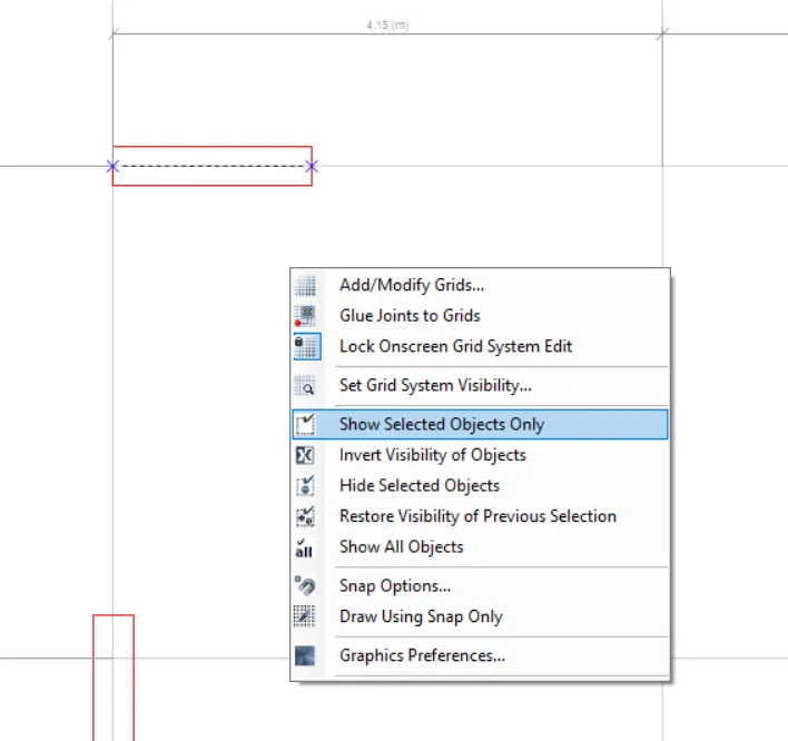
- Select the one shear wall then click on the right button of your mouse
- Then click on the show selected objects only
Step3;-
- Make sure that the shear wall has a pier lable
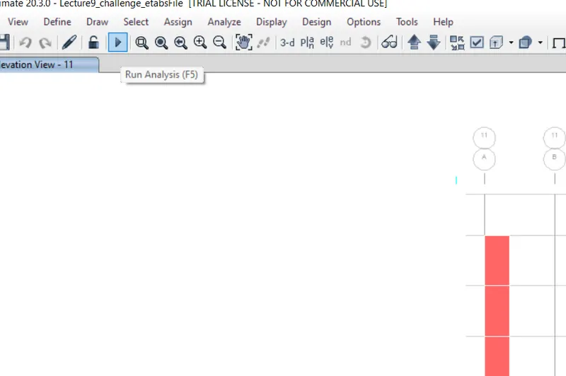
- After looking all these click on the Run analysis or use F5 function key
Step4:-
- After the analysis complete then go for shear wall deisgn
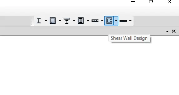
- Click on the shear wall design which is at the right top corner
Step5:-
- Wait for some times untill the shear wall design complete
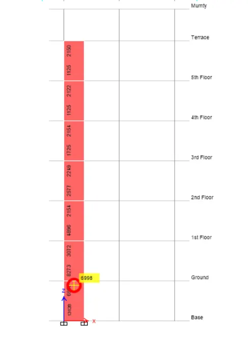
- Then it shown the pier longitudinal reinforcement on the shear wall
Step6:-
- After taken the longitudinal reinforcement then go to pier shear reinforcement
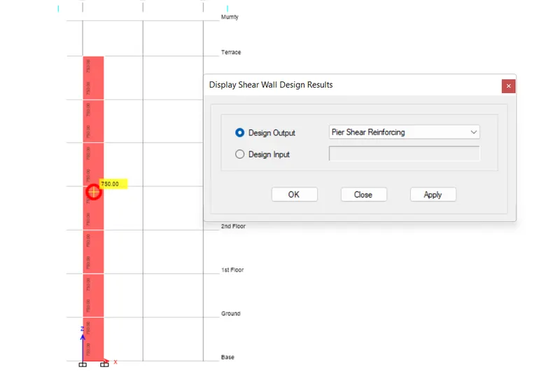
- Click on the shear wall design arrow then then go to the design information change to pier shear reinforcement
- Click on apply then you will get a pier shear reinforcement value
Step7:-
- After taken the pier shear reinforcement then go to pier edge or boundary zone
- Click on the shear wall design arrow then then go to the design information change to pier edge or boundary zone
- Click on apply then you will get a pier edge or boundary zone
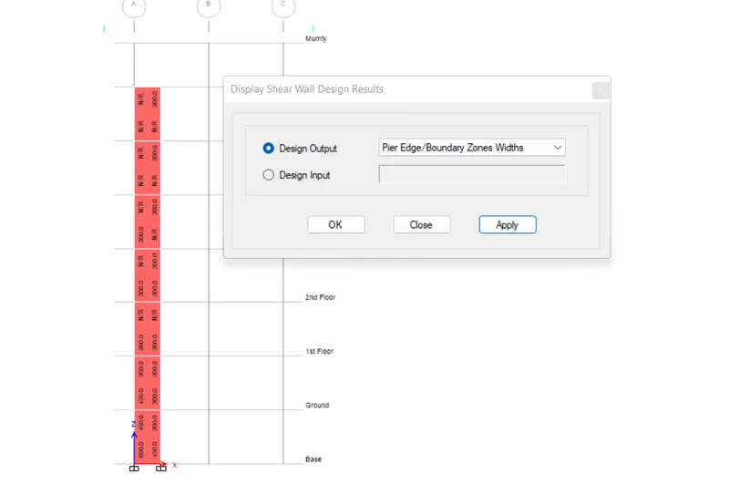
Provide the 600mm boundary zone width at the left and provide 450mm boundary zone width at the right uniform throughout the height
Step8:-
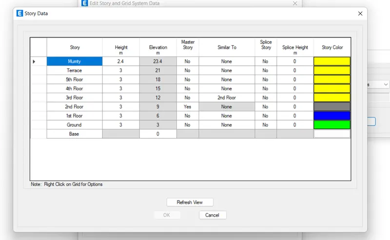
- Take a snap shot of the storey height then insert it here
Step8:-
Detailing guidelines for the shear wall
- Minimum reinforcement for shrinkage and temperature
- Ultimate limit state design rebar requirement
- Ductility rebar requirement
Which is greater we should draw in the detailing
- Classification of shear wall as per IS 13920-2016 clause 10.1.4
hW / LW = 21000/1500 = 14>2
1.4>2, so its a slender wall
- Minimum net vertical reinforcement as per IS 13920-216 table 1
(ρv,net)min = 0.0025+0.01375*(300/1500) = 2363mm^2 (ρv,be)min (ρv,web)min (ρv,net)min
- Minimum vertical reinforcement within boundary element
600mm width at the left
450mm width at the right
- Minimum horizontal reinforcement in shera wall as per the IS 13920-2016 table 1

(ρh) = 750/(300*1000) = 0.0025
hW = 21,000mm
LW = 1500mm
(ρh)min = 0.0025+0.5(21/15 -2)*(0)
(ρh)min = 0.0025
- Maximum diameter of the bar for a shear wall as per IS 13920-2016 clause 10.1.8
1/10th of wall thickness = 1/10 * 300 = 30mm
30mm dia rebar is the maximum rebar but we will use 25mm dia bar which is a commercial rebar
- Determining the number of bar in main bars
From the ETABS we get the longitudinal reinforcement value as Ast = 13128mm^2
No of bars = 13128/490 = 26.79 = 28bars
(490mm^2 is the area of 25mm dia bar)
Confining reinforcement
Confining reinforcement spacing for the boundary element as per the IS 13920-2016 clause 10.4.4
- 1/3rd of the minimum member dimension = 1/3 * 300 = 100mm
- 6 times the smallest main bar = 6*25 = 150mm
- 150mm permisible if vertical bars are spaced at a maximum 200mm
maximum spacing of confining reinforcement in boundary element is 150mm
We use a 8mm dia bar for the confining reinforcement
No of bars = Ast / Area of 8mm bar 4 Legs =
= 750/4*50
= 3.75= 4 No of bars (per meter )
Spacing = 1000/No of bars
= 1000/4 = 250mm c/c (per meter)
Use 4 Nos of bar at 250mm c/c
- Determining the number of shear reinforcement
Ast = 750mm^2
No of bars = Ast / Area of 8mm bar 2 Legs =
= 750/2*50
= 7.5 = 8 No of bars (per meter)
Spacing = 1000/No of bars
= 1000/8 = 125mm c/c (per meter)
Use 8 Nos of bars at 125mm c/c
Confinig reinforcement within boundary element as per IS 13920 - 2016 clause 10.4.4
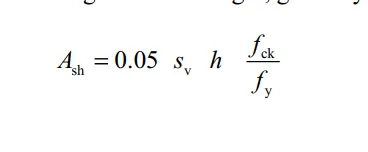
sv = 150mm , h = 1000mm (because of the horizontal reinforcement ), fck = 25, fy = 415
Ash = 0.05*150*1000*(25/415) = 451.80 = 452mm^2 (minimum)
For the deatiling we used
- Use 4 legged 8mm dia at 250mm c/c confining reinforcement (per meter)
- Use 2 legged 8mm dia at 125mm c/c shear reinforcement (per meter)
AutoCAD deatiling ;-
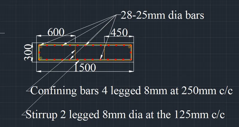
This is the cross section of the shear wall
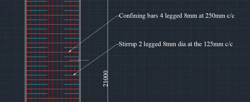
This is the longitudinal section of the shear wall
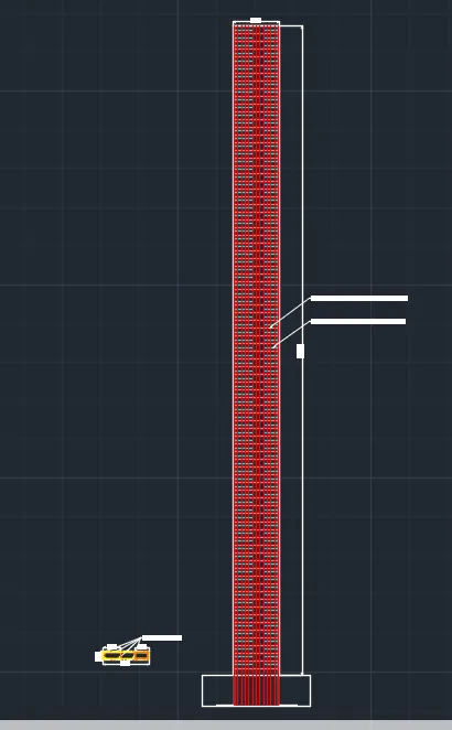
This is the cross section and longitudinal section of the shear wall
Result:-
- Analysis and Design of the shear wall is done according to the IS 13920-2016
- RCC shear wall values of longitudinal reinforcement , shear reinforcement, and boundary edge is taken by the ETABS output results
- The detailing has done according to the values