Modelling of 25 storey building with the specified properties using ETABS
Aim:- Check the building response for seismic force in both x and y direction by analysis and model the 25 building storey building with specified storey in ETABS
Introduction:-
Seismic force :- It is the external force applied to the structure as a result earthquake generated agitation
- In this the earthquake occured at once in a 2500 years
- Seismic cannot be determined it's a less uncertainity
- Seismic force occure at the ground level in all the directions and it has 3degree of freedom they are 2 translational and 1 rotational force
- The base shear starts at the bottom of the buildings when the seismic load occures
ETABS :-
- The full form of ETABS is Extended three dimensional analysis of building system
- ETABS software was started by CSI (Computers and Structural ,Inc
- ETABS is a engineering software which is used for multistorey analysis and design
- In this software we can analyse and design the seismic load, wind load, and other loads
- In this software we are defining and assigning the materials, frame sections, slab sections diaphragm etc.,
- This software give the proper output result to that analysed model
Procedure:-
Step1:-
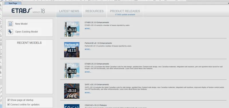
- Open the ETABS software by double clicking on it
- Then click on the new model option which is at left side of the screen
Step2:-
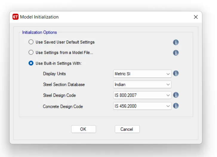
- After click on the new model then model initialization dialouge box will open
- Select the use built in settings with
- Set the unit as metric, database as Indian, Steel code book as IS 800:2007 and Concrete design code as IS 456:2000
- Then click on OK
Step3:-
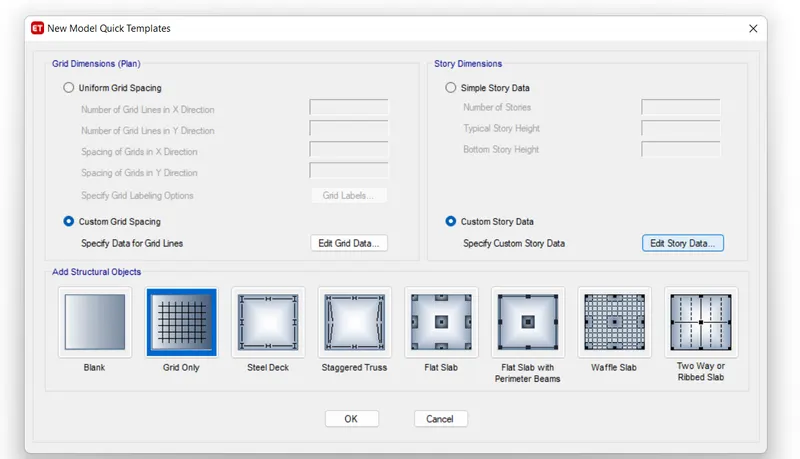
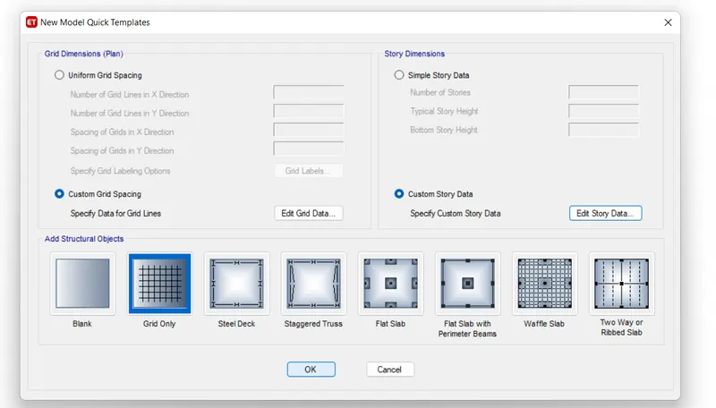
- After completion of model initialization then New model Quick template dialouge box opens
- Select the custom grid spacing and custom storey data and then edit accordingly
Step4:-
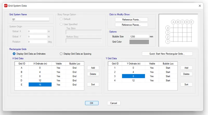
- Mention the Grid spacing for the both x and y direction
- The spacing of storeys are 4m offset
- Then click on OK
Step5:-
- After editing the Grid spacing then select the Storey data then edit that
- Click on the edit storey data to edit the stories
Step6:-
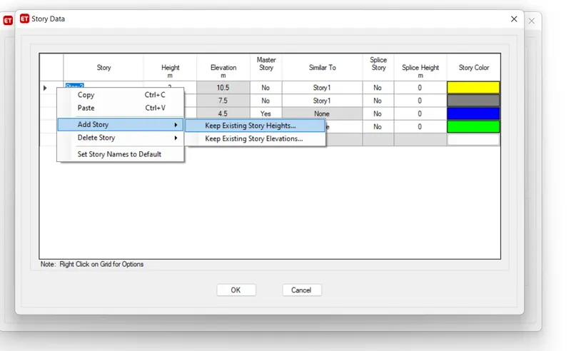
- Click on the storey 2, then click on the right button of your mouse
- Then click on the add storey then click on the keep existing storey heights
Step7:-
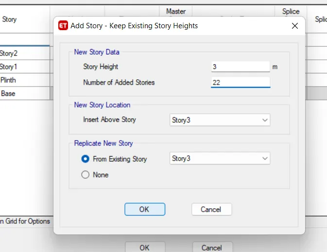
- After that add storey dialouge box opens
- Then change the number as 22 because we require 25 number of stories, here 2 stories are already assigned
- Then click on OK
Step8:-
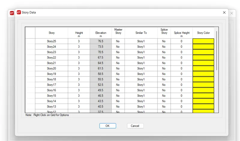
- Change the storie 3 to 25 as a similar storey
- Then click on OK
- Here there are 25 stories for the building
- Height of the building should be 3m
- Stories in the table are Base, Plinth, Storey 1 to Storey 25
- Make the Storey 1 as a Master storey and Make the Storey from 2 to 25 as a similar to
Step9:-
- After completing all the grid lines and storey data
- Click on the OK
Step10:-
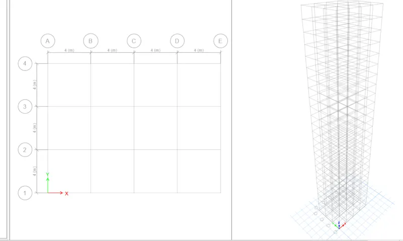
- This is the how the structure looks like after completing all the information
- Here the plan view and 3D view are shown in this software in one screen
Step11:-
- After completing all the settings define the materials and define the sections for the column, beam and slabs
- Click on the define and select the material properties
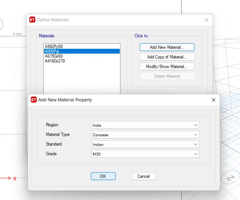
- Click on the new material to create a new material
- Select the required properties of the material
- Region as India, Material type as concrete, Standard as Indian, Grade as M-30
- Then click on OK
Step12:-
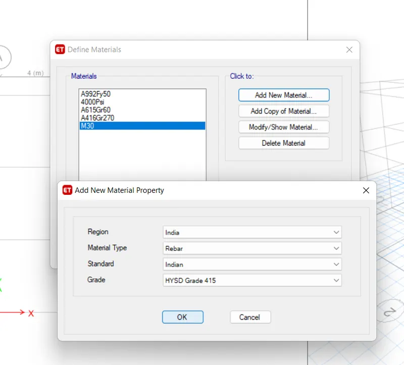
- Click on the new material to create a new material
- Select the required properties of the material
- Region as India, Material type as Rebars, Standard as Indian, Grade as HYSD Grade 415
- Then click on OK
Step13:-
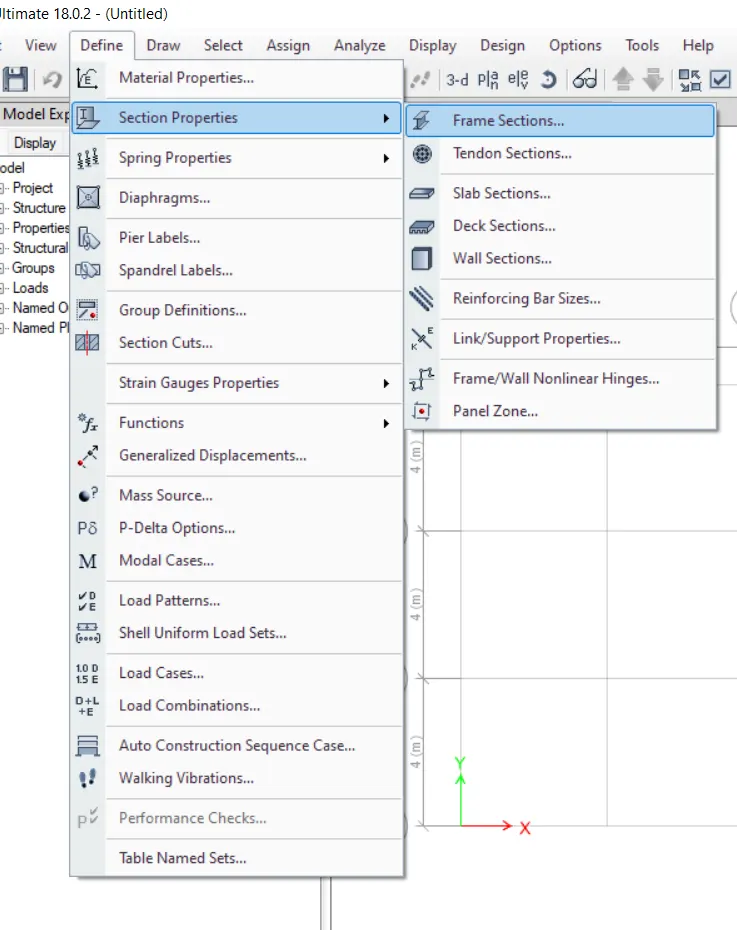
- To define a section properties
- Click on the define, then click on the section properties, then select on the frame section
Step14:-
- After selecting the frame section
- Click on the add new property to create a new frame section
- Select the rectangular concrete for the beam then click on OK
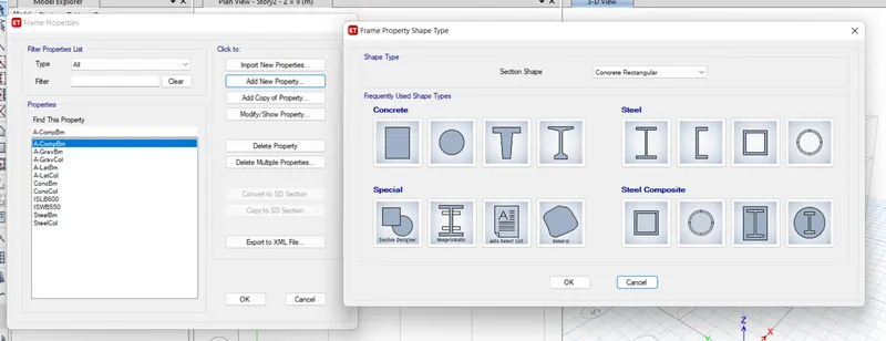
Step15:-
- After clicking on OK then frame section property data dialouge box opens
- Change the property name as Beam 300x400, Change the material as M-30, Change the dimensions
- Click on the modify/show Rebars to get more
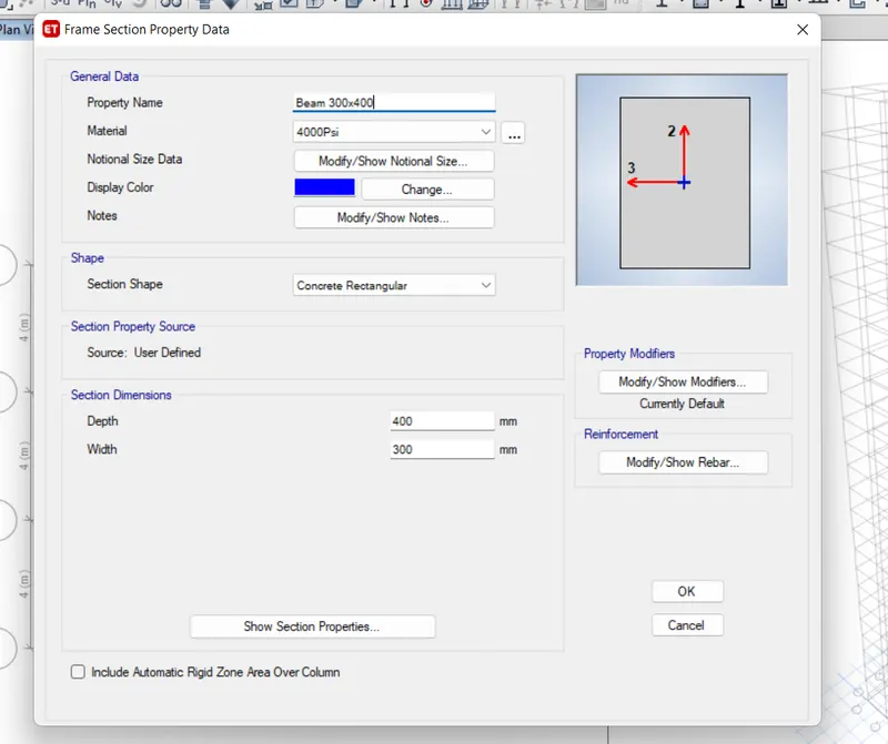
Step16:-
- After opening the modify/show Rebars then this dialouge box opens
- Select the M3 Design only (Beam)
- Then change the longitudinal and Confinement bars as HYSD 415
- Then click on OK
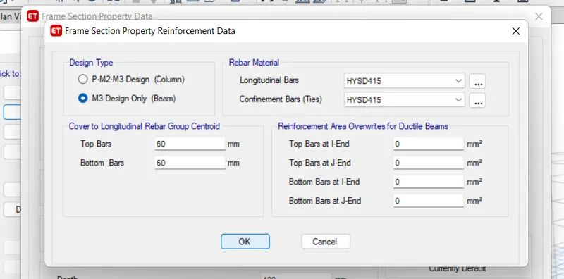
Step17:-
- Select the frame section
- Click on the add new property to create a new frame section
- Select the rectangular concrete for the column then click on OK
- After clicking on OK then frame section property data dialouge box opens
- Change the property name as Column 800x800, Change the material as M-30, Change the dimensions
- Click on the modify/show Rebars to get more
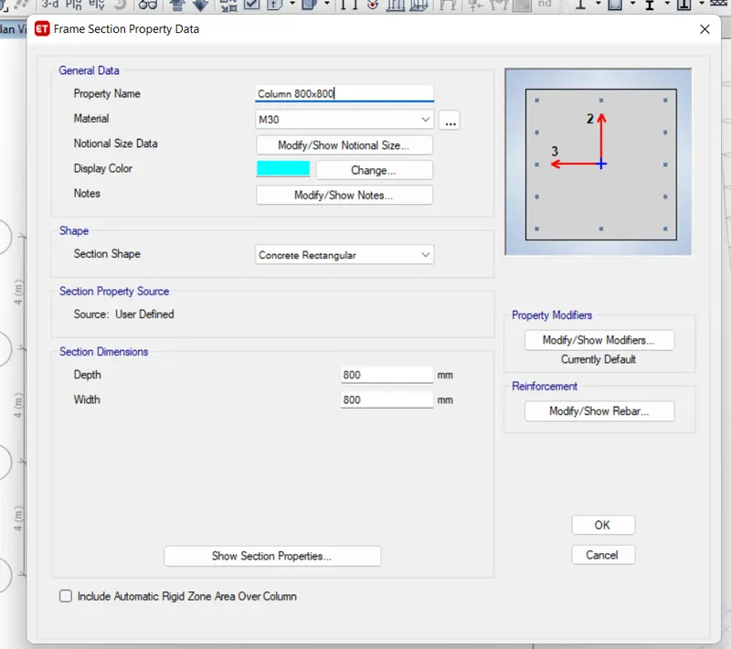
Step18:-
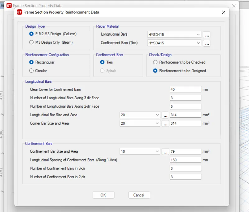
- After opening the modify/show Rebars then this dialouge box opens
- Select the P-M2-M3 Design (Column)
- Then change the longitudinal and Confinement bars as HYSD 415
- Then click on OK
Step19:-
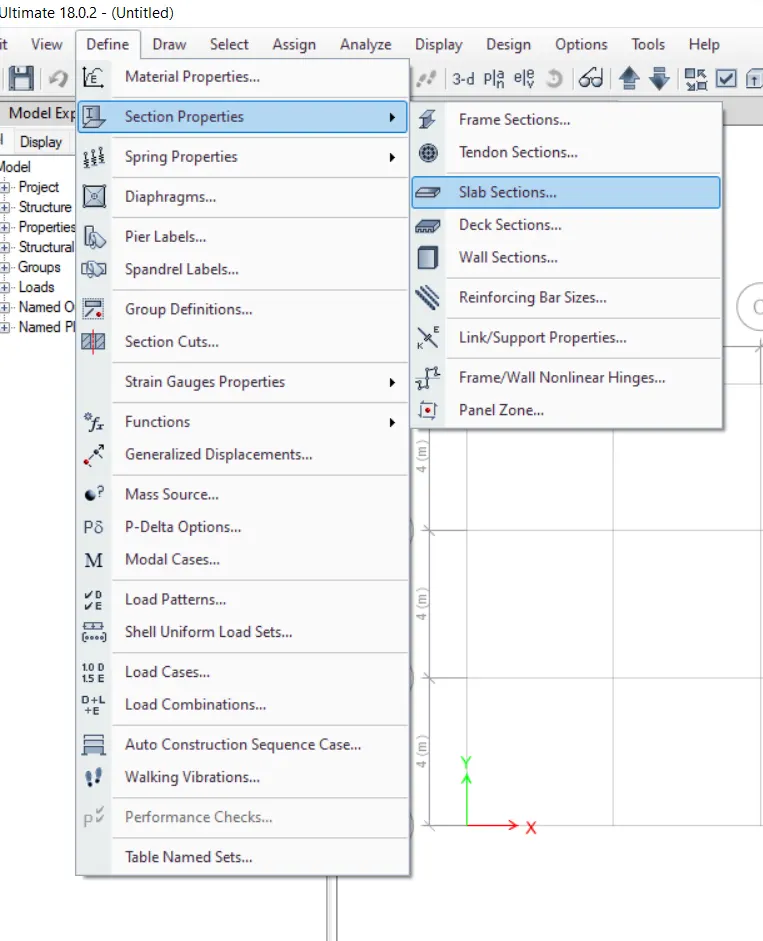
- To create a slab
- Click on the define then select the section properties then click on slab sections
Step20:-
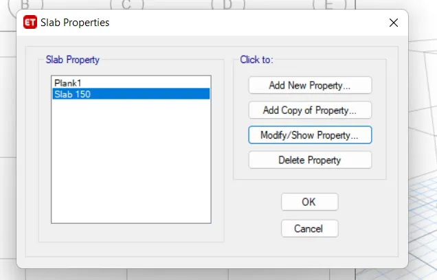
- After selecting slab section the slab properties dialouge box opens
- Then click on the modify/show properties to change the properties
Step21:-
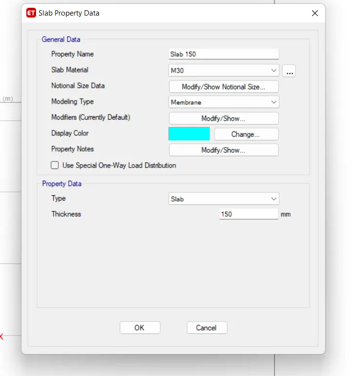
- Change the property name as Slab 150, change the slab material as M-30, and change the slab thickness
- Then click on OK
Step22:-
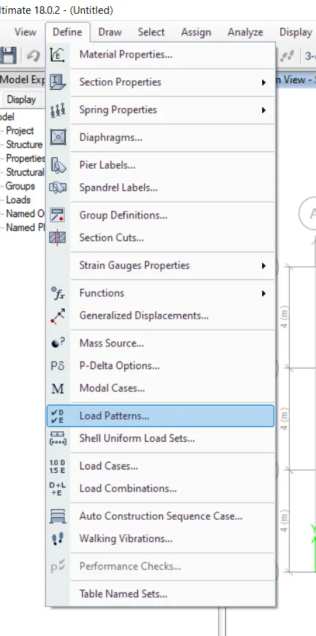
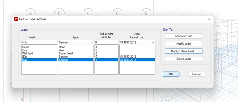
- To define the load pattern
- Click on the define then click on the load pattern
Step23:-
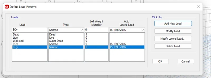
- Add the load patterns
- Dead load, Live load, Wall load, Seismic load in both x and y direction
- Mention the code book for the seismic load
Step24:-
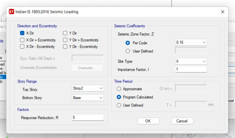
- Click on the seismic load in x- direction then select the modify lateral load
- Except X dir uncheck all the direction andd eccentricity
- Change the seismic zone factor to 0.16
Step25:-
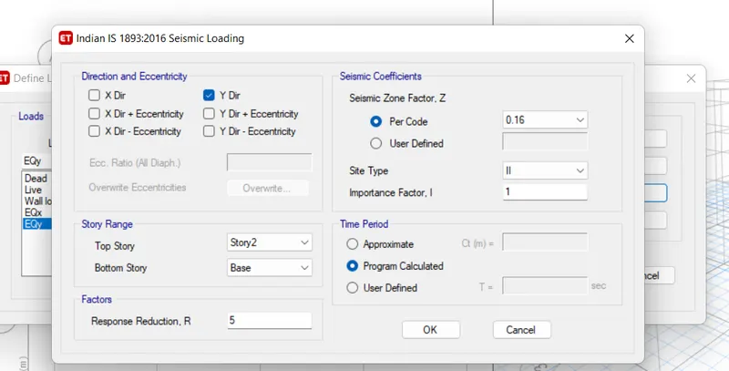
- Click on the seismic load in y- direction then select the modify lateral load
- Except Y dir uncheck all the direction andd eccentricity
- Change the seismic zone factor to 0.16
Step26:-
- After making all the settings in the load pattern
- Click on OK
Step27:-
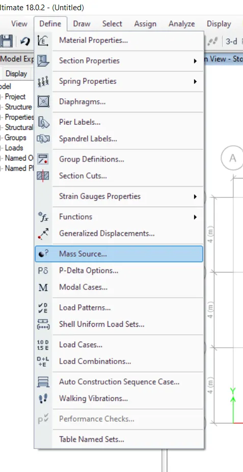
- To define the mass source
- Click on the define then click on the mass source
Step28:-
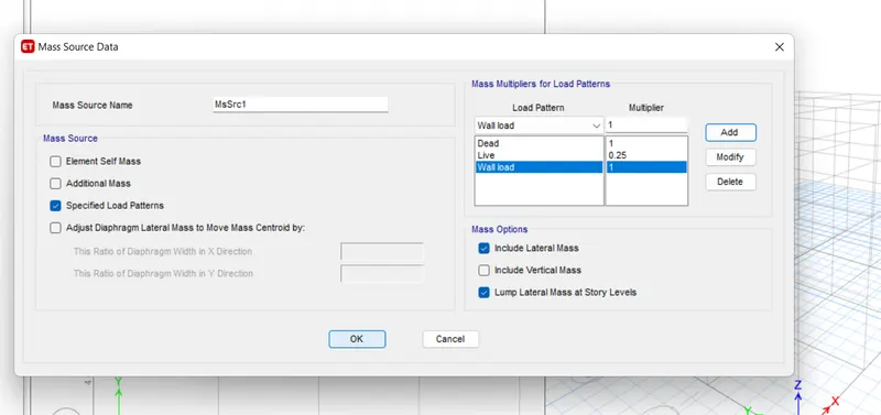
- After selecting mass source then mass source data dialouge box opens
- Check only the specified load patterns
- Select the load patterns of dead load of 1 multiplier, live load of 0.25 multiplier, wall load of 1 multiplier
- Then click on OK
Step29:-
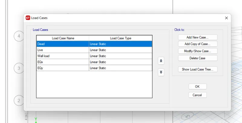
- To define the load cases
- Click on the define then click on the load cases
- All the load are automatically selected
- Then click on OK
Step30:-
- To define the load combination
- Click on the define then click on the load combination
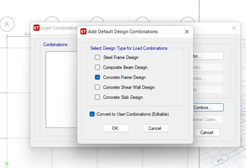
- Select the default combination
- Then click on the concrete frame design and convert to user combination
- Then click OK
Step31:-
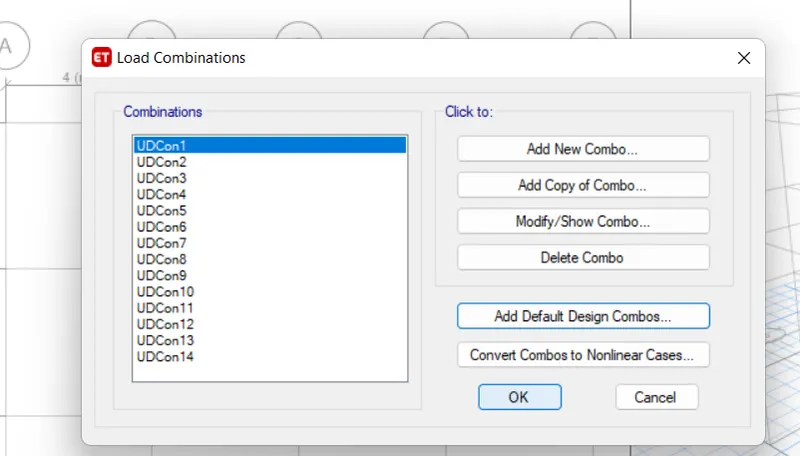
- After selecting the concrete frame design
- All the load combinations are automatically appears here
- Then click on OK
Step32:-
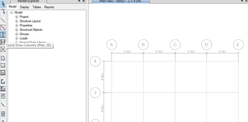
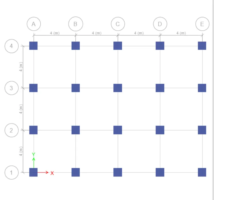
- Draw the column at the junction of the grid lines
- Click on the Quick draw column icon in the tool bar
Step33:-
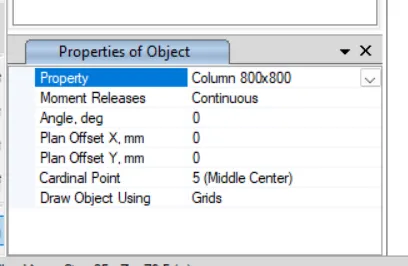
- Ensure that it should be the column property
- The size of the column should be 800x800mm
Step34:-
- Place the mark at the junction of the grid lines
- Then the column will appear at the junction
Step35:-
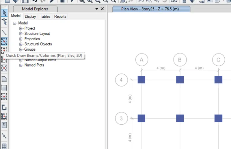
- Draw the beam along the junction of the grid lines
- Click on the Quick draw beam/column icon in the tool bar
Step36:-
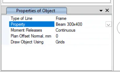
- Ensure that it should be the beam property
- The size of the beam should be 300x400mm
Step37:-
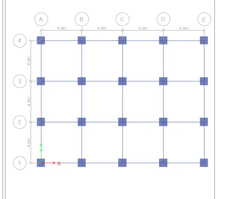
- Place the mark along the junction of the grid lines
- Then the beam will appear along the junction
Step38:-
- Draw a slab in the model
- Select the Quick draw floor / wall to draw the slab
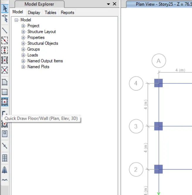
Step39:-
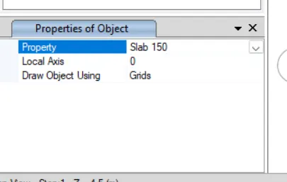
- Ensure that the selected property is slab 150
- The 150 reffers to the thickness
Step40:-
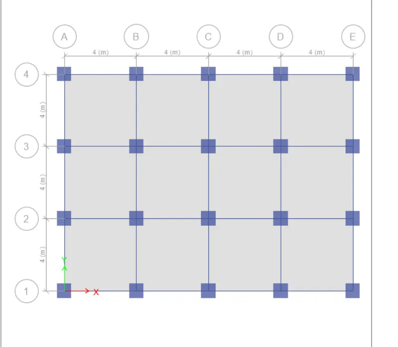
- Select the similar storey
- Click on the region to place the slab
- This is how the slab look like
Step41:-
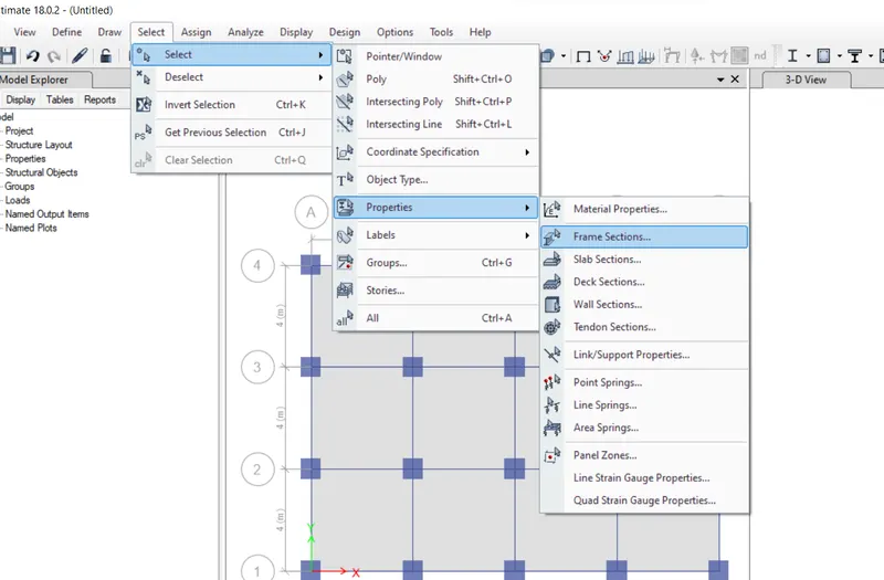
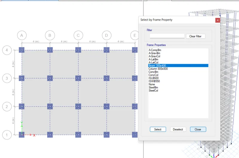
- To select the frame section
- Click on select then click on select then click on properties then select the frame sections
- Then select all the beams
Step42:-
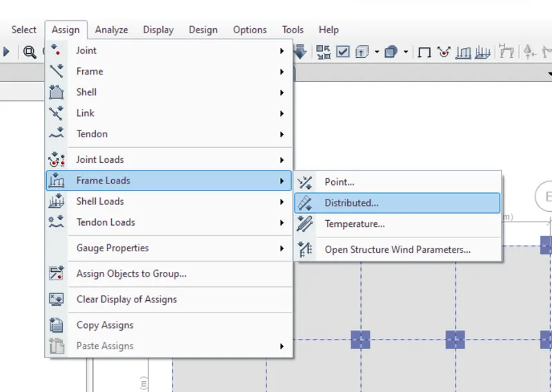
- Assign the loads for the frame element
- Click on the assign then click on the frame load then click on distributed
Step43;-
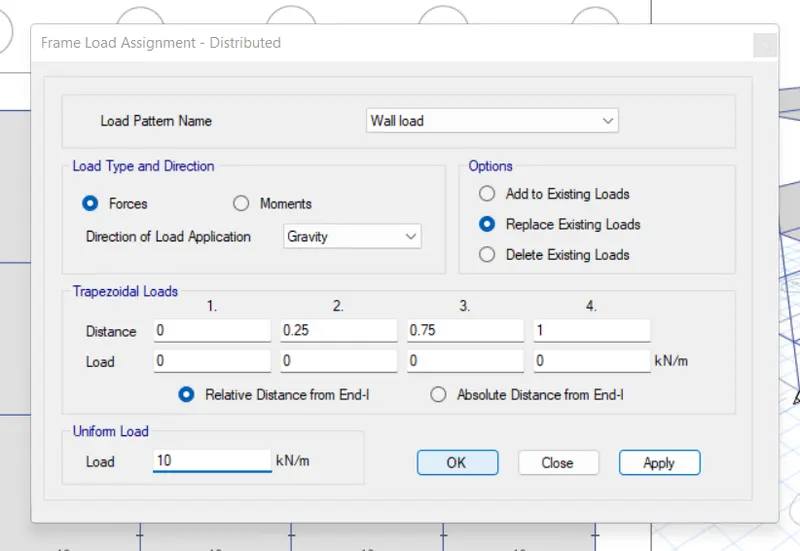
- To select a slab section
- Then select a assign then go to shell load then select a distributed
- Select the load pattern as wall load
- Then take a uniform load as a 10 KN/m
- Then click on apply then click on OK
Step44:-
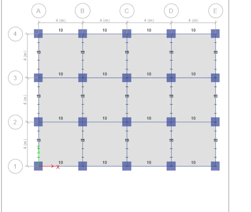
- After applying the 10 KN/m load
- The load assigned to the beam is shown as below
Step45:-
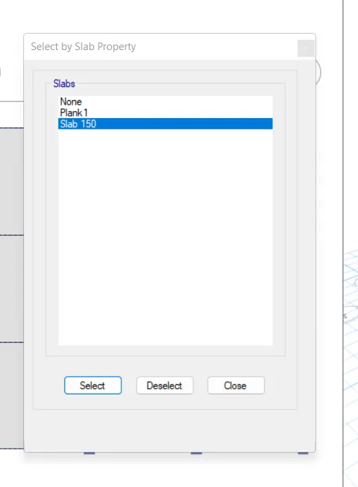
- To select the slab section
- Click on select then click on select then click on properties then select the slab sections
Step46:-
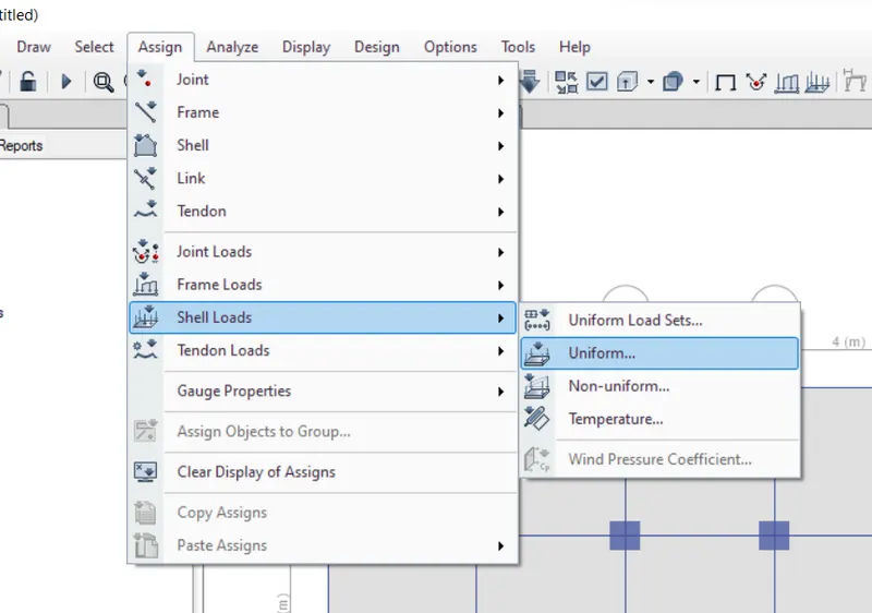
- To assign the loads to the slab
- Click on the assign then click on the shell load then click on uniform
Step47 :-
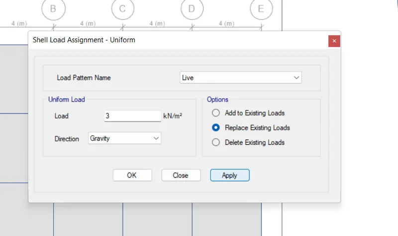
- Select the load pattern as live
- Then take a uniform load as a 3 KN/m
- Then click on apply then click on OK
Step48:-
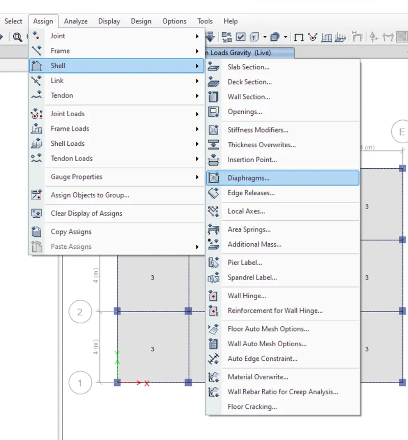
- To provide the diaphragm
- First select the slab section
- Click on assign then click on shell then click on diaphragm
Step49:-
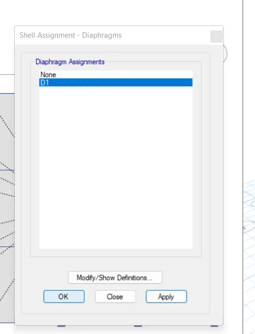
- The diaphragm dialouge box opens
- Then select the diaphragm assignment as D1
- Then click on apply then click on OK
Step50:-
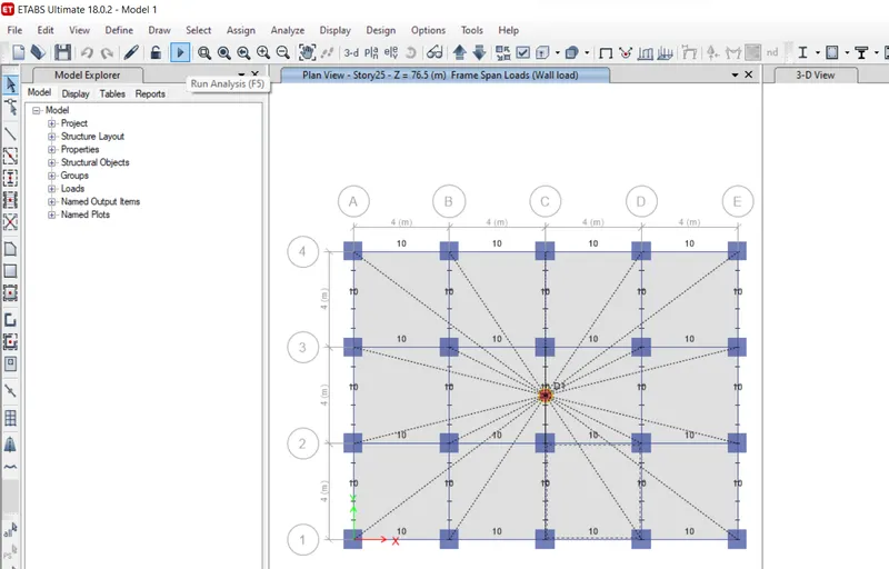
- At last Run the analysis by clicking the Run analysis button or by clicking F5
- Give a time for analysis then it will give a result of it
Result:-
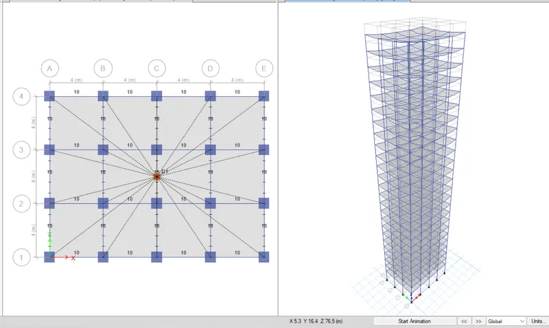
This is the snap shot of buidling undergo seismic action and also deflection in both x and y direction
Comaprision of time period for the building model
|
Criteria |
Desirable solution |
Exercise result |
|
|
Fundamental translational natural period |
X - Direction |
4.4 s |
4.85 s |
|
Y - Direction |
4.2 s |
4.65 s |
|
|
Torsional irregularity |
IS 1893-2016 (Part 1) Table 5 |
Torsional mode time period should be lesser than X and Y direction time period |
Yes (3.6 s) |
|
Vertical irregularity |
IS 1893-2016 (Part 1) Table 6 Clause 7 |
First three mode together should contribute at least 65% in mass participation factor in each principal direction |
Yes (In the first mode only it occupies the 85%) |
|
Fundamental lateral natural periods in two principal plane directions are away from each other by at least 10% |
No (If we deduct the 10% then we will get a answer as 3.37 but the mode 1 and mode 2 almost same) |
||
|
Inter storey drift |
IS 1893-2016 (Part 1) Clause 7.11.1.1 |
Storey drift shall not exceed 0.004 times the storey height for the base shear with no load factor (4x10^-3) |
Yes (The storey drift in EQx we get near 1.35 and in EQy we get slightly greater than 1.35) |