Creating a Residence Layout, Seating plan, Toilet and Utility room plan using AutoCad
Aim:- To create Residential layout, seating plan, toilet and utility plan by using AutoCAD
Introduction:-
Resident layout
- Resident layout is a geographical localize community within a large city, town or suburb
- Resident layout refers to the from, scale and function of buildings and open space for the purpose of creating functionality, efficient and aesthetically pleasing physical environment for living, working etc.,
Seating plan
- Seating plan is made at outside of the building in the drawing
- Seating plan is required for sitting to the guests
Toilet and utilities
- Toilets and utilities are draft inside the building in the drawing
AutoCAD:-
- We use different commands for creating this drawings
- The different commands are construction line, offset, arc, circle etc.,
Procedure:-
- Go to start menu, click on Start drawing
- Type stratup (Enter) in command line
- Enter the new value of start up:1
- Go to application menu and select new or type new in command line
- In the "create new drawing" dialogue box contains imperial type of systems and metric type of system
- We select the metric system in the "start from scratch" option
- After that in Advance setup option select the decimal unit system in the units
The above procedure should be followed every time when the new sheet is opened
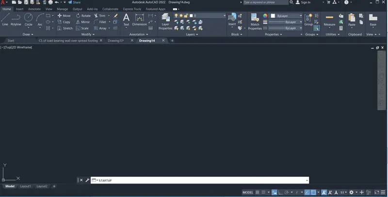
Entering the start up command in the command line
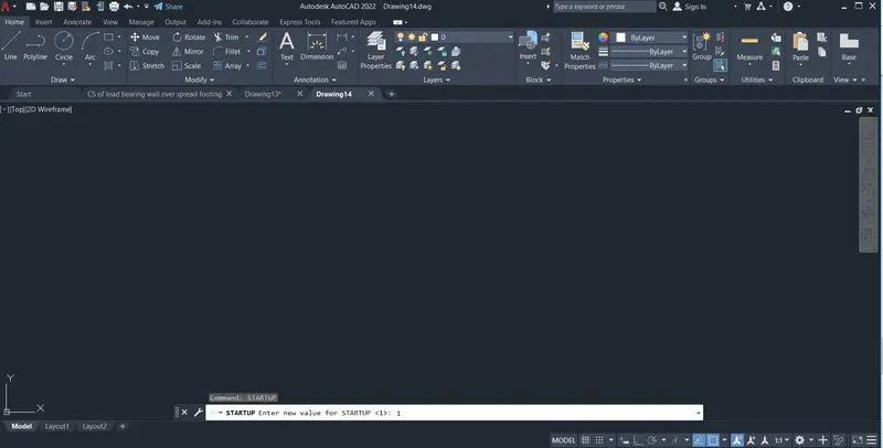
Entering the value 1 for the start up
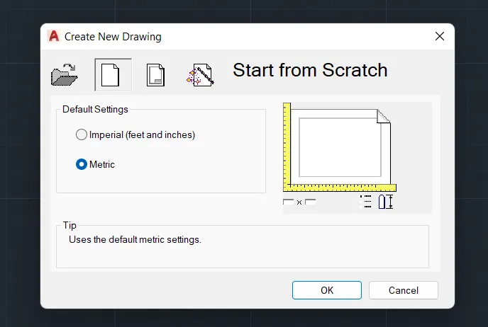
When we go to the new file then we get this file select the metric from start from scratch
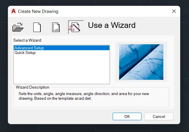
Then advance setup setting should be done by clicking OK
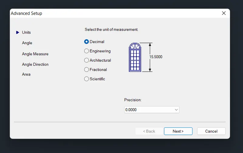
Keep the units in decimal and adjust precision then click next
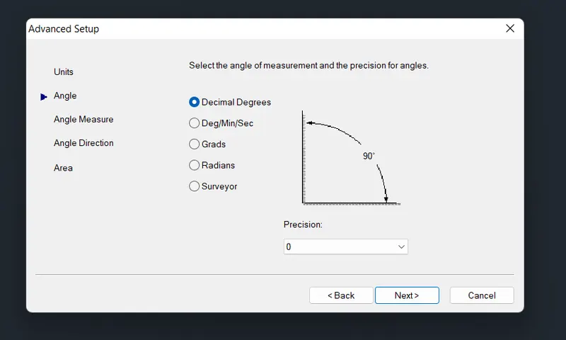
Keep angle in decimal degree and adjust precision then click next
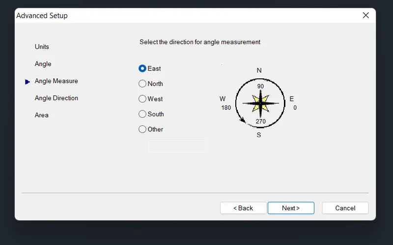
Select the angle measurement in east and click on next
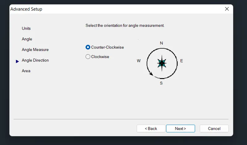
Select angle direction in counter clockwise and click on next
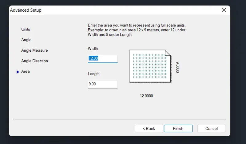
Keep the width as 12m and length of 9m as default and click on finish
Aim:- To draft the residential layout
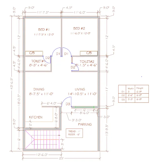
Procedure:-
By using direct distance entry method
- Here all the units are in Engineering (inches and feet's)
- Select the construction line tool by entering XL (Enter) in the command line
- Select the vertical line and place it any where on the screen
- Next by using a same command (construction line) select horizontal line and place it on the screen
- Take a offset of 9" for the outer wall from the vertical line
- Take a offset of 9" for the outer wall from the horizontal line
To get Bed room 1 and 2
- Take a offset of 11'-7.5" right side from the 9" outer wall vertical line
- Take offset of 4.5" right side from the 11'-7.5" line
- Take a offset of 11'-6" right side from the 4.5" line
- Take a offset of 9" right side from the 11'-6" line
- Take a offset of 12'-0" downwards from the 9" outer wall horizontal line
- Trim off unwanted lines inside the rooms
To get toilets
- Take a offset of 4.5" downwards from the 12'-0" line to get inner wall
- Take a offset of 4'-6" downward from the 4.5" inner wall line
- Take a offset of 8'-3" from the left side of the vertical line and take a offset of 8'-1.5" from the right side of the vertical line
- Take a offset of 4.5" from both the 8'-3" and 8'-1.5" lines right side and left side respectively
- Trim off unwanted lines inside toilets
To get Dining and Living room
- Take a offset of 11'-0" downwards from the 4.5" wall which is used for the toilets
- Here there is no wall in between the dining and living
To get Parking
- Take a offset of 9" wall from the living room wall which is a main wall
- The remaining area left is used as a parking area which has a dimension of 11'-9"x13'-9.5"
To get kitchen
- Take a offset of 4.5" from the dining wall to create the kitchen
- Take a offset of 6'-8" from the 4.5" wall to downwards
- Take a distance of 6'-4" from the main door to create a wall for kitchen the remaining portion is for opening
- Take a offset of 9" from the 6'-4" line to create the main wall
To get stairs
- Take a offset of 6'-0" from the 9" main wall which is near the kitchen
- Take a offset of 12'-6" from the vertical line to create the steps
- The width of the first flight is 3' and width of second flight is 3'
- The tread size of the steps is 1' and riser size of step is 6"
To draft door D3
- Draw a line of 3'-3" and create a frame of 2" vertical line and 1" horizontal line by using line
- By using a start end angle method in arc draw a curve having an angle of 90 degree
To draft door D1
- Draw a line of 3'-0" and create a frame of 2" vertical line and 1" horizontal line by using line
- By using a start end angle method in arc draw a curve having an angle of 90 degree
To draft door D2
- Draw a line of 2'-6" and create a frame of 2" vertical line and 1" horizontal line by using line
- By using a start end angle method in arc draw a curve having an angle of 90 degree
To draft Window
- Draw a line from the mid point of the living room to the wall
- Take a offset of 3'-0" from the mid line of living room to the left and right side of that line
- Join a line to the mid of 2 lines which is attached to room wall
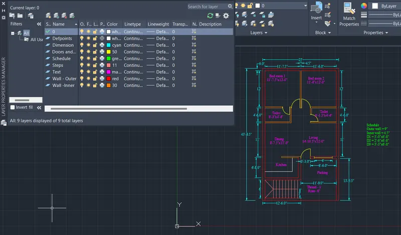
Layers for residential layout
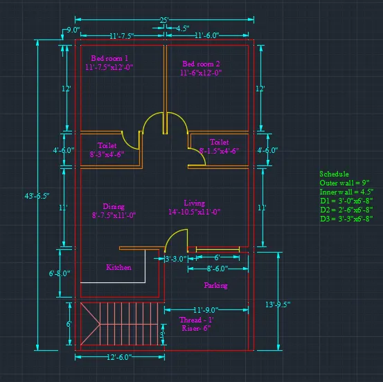
Resident layout draft by using AutoCAD
Dimension layers are
- Wall -outer - Red
- Wall -inner - ACI 30
- Doors and windows - ACI 50
- Dimension - Cyan
- Text - Magenta
- Schedule - Green
- Steps - ACI 11
Result:-
Layers for residential layout
Resident layout draft by using AutoCAD
Aim:- To draft the seating plan
Procedure:-
By using direct distance entry method
- Here all the units are in millimetre
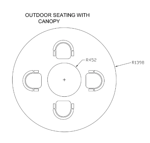
- Draw a circle having a radius 452mm and by using same centre draw a another circle having a radius 1398mm
- Then create a seating
To create a seating
- Draw a horizontal line of 500mm then draw a vertical line having a distance 270mm at both the sides
- By using a start end angle method draw an arc having an angle of 180 degree
- Take a offset of 25mm from the arc and then again take a offset of 50mm from the 25mm arc which is used for support
- create a rectangle by using a line which has a dimension of 50mmx120mm below the support
- Use a fillet option to get a smooth curve at the edges which has a radius 50mm
- Use a array for taking more number of object
- Use a polar array in array option give an angle as 90 degree so that the 4 seating can arrange equally
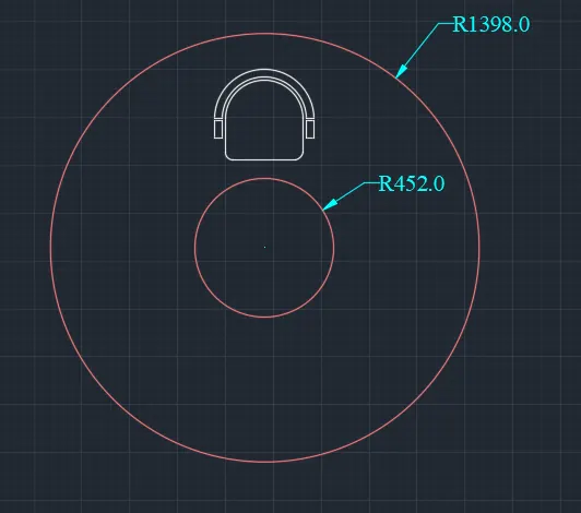
Out door single seating with canopy
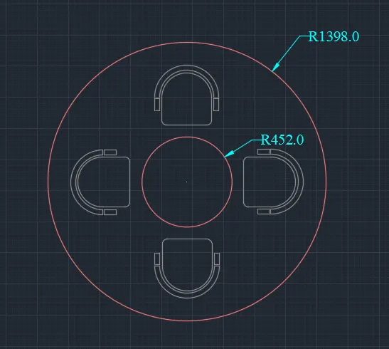
Out door seatings with canopy
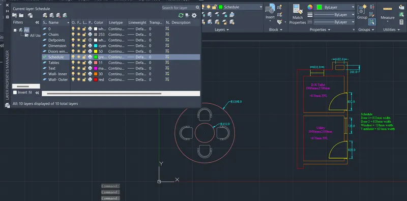
Layers for both out door seating , toilet room and utility room
Dimension layers are
- Table 1 Radius 452mm - ACI 11
- Table 2 Radius 1398mm - ACI 11
- Chairs - ACI 253
Result:-
Out door single seating with canopy
Out door seatings with canopy
Layers for both out door seating , toilet room and utility room
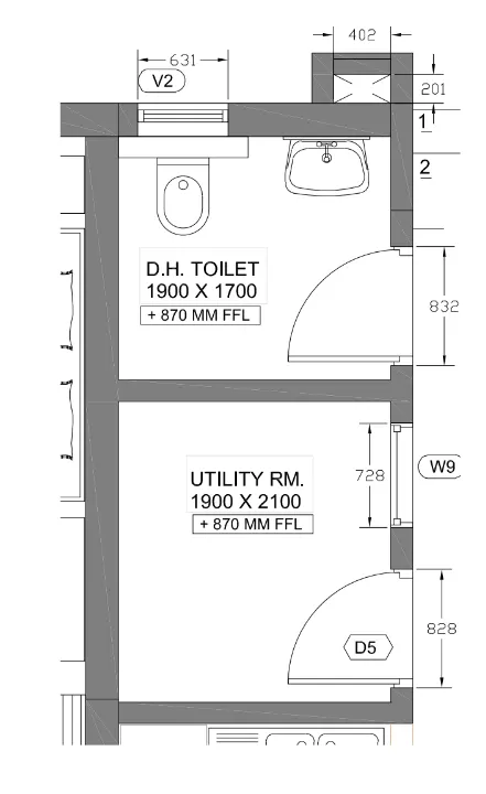
Aim:- To draft the toilet and utility room plan
Procedure:-
By using direct distance entry method
- Here all the units are in metric (millimetre)
- Select the construction line tool by entering XL (Enter) in the command line
- Select the vertical line and place it any where on the screen
- Next by using a same command (construction line) select horizontal line and place it on the screen
- Take a offset of 300mm for the outer wall from the vertical line
- Take a offset of 300mm for the outer wall from the horizontal line
To get D.H Toilet
- Take a offset of 1900mm right side from the 9" outer wall vertical line
- Take offset of 150mm right side from the 1900mm line
- Take a offset of 1700mm downwards from the 300mm outer wall horizontal line
- Trim off unwanted lines inside the rooms
To get the utility
- Take a offset of 150mm downwards from the 1700mm line to get inner wall
- Take a offset of 2100mm downward from the 150mm inner wall line
- Take a offset of 150mm from the 2100mm line
- Take a offset of 1900mm from the left side of the vertical line
- Take a offset of 150mm from both the 1900mm from the left side
- Trim off unwanted lines inside toilets
Create another area above the D.H Toilet
- Draw a line of 402mm horizontal line from the upside right corner of the D.H Toilet
- Draw a vertical line of 201mm at both the ends
- Draw the 402mm horizontal line at the ends of 201mm line which is upside
- Take a offset of 150mm at left, right and upside
To draft Door
- Draw a line of 832mm and create a frame of 50mm by using line
- Draw again line of 832mm from the frame
- By using a start end angle method in arc draw a curve having an angle of 90 degree
To draft Door
- Draw a line of 828mm and create a frame of 50mm by using line
- Draw again line of 828mm from the frame
- By using a start end angle method in arc draw a curve having an angle of 90 degree
To draft Window
- Draw a line from the mid point of that room to the wall
- Take a offset of 364 from the mid line of utility room to the left and right side of that line
- Join a line to the mid of 2 lines which is attached to room wall
To draft Ventilator
- Draw a line from the mid point of that room to the wall
- Take a offset of 315.5 from the mid line of D.H toilet room to the left and right side of that line
- Join a line to the mid of 2 lines which is attached to room wall
Layers for both out door seating , toilet room and utility room
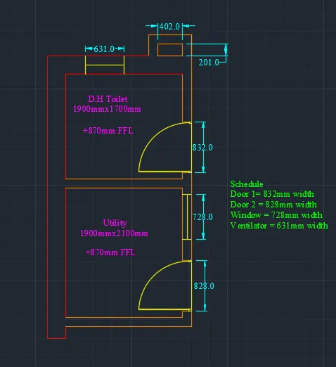
Toilet and utility room by using AutoCAD
Dimension layers are
- Wall -outer - Red
- Wall -inner - ACI 30
- Doors, windows and ventilator - ACI 50
- Dimension - Cyan
- Text - Magenta
- Schedule - Green
Result:-
Layers for both out door seating , toilet room and utility room
Toilet and utility room by using AutoCAD