Creation of geometries by Coordinate system methods using AutoCad
Aim :- To draft the given geometry in AutoCAD by using different coordinate system
Use all the coordinate system to draft the P1 and P2 geometry
Use any one of the coordinate system to draft the remaining geometry
Introduction:-
Coordinate system
- Coordinate system is a system used to determine the position of the points by using numbers
- Coordinate system may be 2D or 3D coordinate system
- If it's 2D it contains x and y directions (0,0)
- If it's 3D it contains x, y and z directions(0,0,0)
There are different types of coordinate system
1. Absolute coordinate system
2. Relative coordinate system
a) Relative rectangular coordinate
b) Relative polar coordinate
3. Direct distance entry method
1. Absolute coordinate system
- In this system the x and y axis points are mentioned at some distance with respect to the origin (0,0)
- Here x and y represents the distance
2. Relative coordinate system
- In this system the first point of x and y axis is absolute at every time (0,0) and then after the first point all the next points should be with respect to their previous point
- Here x and y represents the distance with respect to previous point
a) Relative rectangular coordinate system
- In this system the coordinates specify each points by using a pair of numbers in x and y axis
- Here the starting pair of numbers is in absolute method (0,0) and the next points should be with respect to previous point
- In command line the relative rectangular coordinate system format should be in @x,y
- Here x and y represents the distance with respect to previous point
b) Relative polar coordinate system
- In this system the coordinate specifies the distance and angle of the point with respect to the previous point
- Here the starting point is in absolute method (0,0) and the next points should be with respect to previous point
- In command line the relative polar coordinate system format should be in @x<y
- Here x represents distance and y represents the angle with respect to previous point
3. Direct distance entry method
- This method is used to draw the different shapes of geometries in AutoCAD
- This method is helps the user to draw the geometry by simply moving or pointing the cursor in any direction
- While moving or pointing the cursor in any direction enter the required distance in the command bar
Procedure:-
- Go to start menu, click on Start drawing
- Type stratup (Enter) in command line
- Enter the new value of start up:1
- Go to application menu and select new or type new in command line
- In the "create new drawing" dialogue box contains imperial type of systems and metric type of system
- We select the imperial system in the "start from scratch" option
- After that in Advance setup option select the decimal unit system in the units
The above procedure should be followed every time when the new sheet is opened
P1
Aim:- To drafting P1 geometry in AutoCAD by using absolute, relative rectangular, polar coordinate system and direct distance entry method
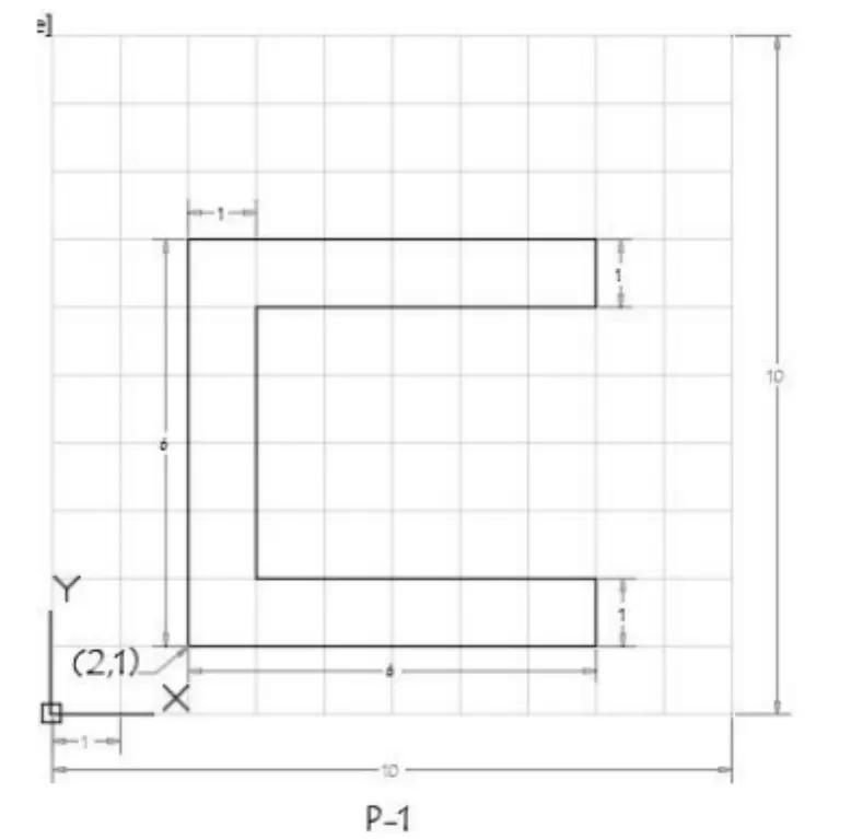
1. By using Absolute coordinate method
- Select the line tool by entering L (Enter) in the command line
- Specify the starting coordinate point 1 as 2,1 in the command line
- Specify the next coordinate point 2 as 2,7 in command line
- Specify the next coordinate point 3 as 8,7 in command line
- Specify the next coordinate point 4 as 8,7 in command line
- Specify the next coordinate point 5 as 3,7 in command line
- Specify the next coordinate point 6 as 3,2 in command line
- Specify the next coordinate point 7 as 8,2 in command line
- Specify the next coordinate point 8 as 8,1 in command line
- Then click close on command line
Result:-
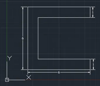
2. By using Relative rectangular method
- Select the line tool by entering L (Enter) in the command line
- Specify the starting coordinate point 1 as 2,1 in the command line
- Specify the next coordinate point 2 as @ 0,6 in command line
- Specify the next coordinate point 3 as @ 6,0 in command line
- Specify the next coordinate point 4 as @ 0,-1 in command line
- Specify the next coordinate point 5 as @ -5,0 in command line
- Specify the next coordinate point 6 as @ 0,-4 in command line
- Specify the next coordinate point 7 as @ 5,0 in command line
- Specify the next coordinate point 8 as @ 0,-1 in command line
- Then click close on command line
Result:-
3. By using relative polar coordinate system
- Here the direction of angle measurement is from "East" and the orientation of angle measurement is "clock wise" direction
- Select the line tool by entering L (Enter) in the command line
- Specify the starting coordinate point 1 as 2,1 in the command line
- Specify the next coordinate point 2 as @ 6<270 in command line
- Specify the next coordinate point 3 as @ 6<0 in command line
- Specify the next coordinate point 4 as @ 1<90 in command line
- Specify the next coordinate point 5 as @ 5<180 in command line
- Specify the next coordinate point 6 as @ 4<90 in command line
- Specify the next coordinate point 7 as @ 5<0 in command line
- Specify the next coordinate point 8 as @ 1<90 in command line
- Then click close on command line
Result:-
4. By using direct distance entry method
- Select the line tool by entering L (Enter) in the command line
- Specify the starting coordinate point 1 as 2,1 in the command line
- Enter the length of the point 2 as 6 in command at +ve y-axis
- Enter the length of the point 3 as 6 in command at +ve x-axis
- Enter the length of the point 4 as 1 in command at -ve y-axis
- Enter the length of the point 5 as 5 in command at -ve x-axis
- Enter the length of the point 6 as 4 in command at -ve y-axis
- Enter the length of the point 7 as 5 in command at +ve x-axis
- Enter the length of the point 8 as 1 in command at -ve y-axis
- Then click close on command line
Result :-
P2
Aim:- To drafting P2 geometry in AutoCAD by using absolute, relative rectangular, polar coordinate system and direct distance entry method
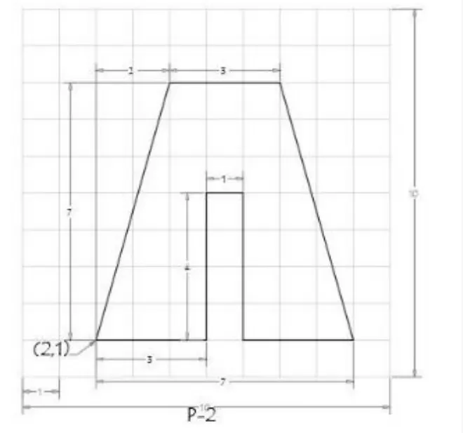
1. By using Absolute coordinate method
- Select the line tool by entering L (Enter) in the command line
- Specify the starting coordinate point 1 as 2,1 in the command line
- Specify the next coordinate point 2 as 4,8 in command line
- Specify the next coordinate point 3 as 7,8 in command line
- Specify the next coordinate point 4 as 9,1 in command line
- Specify the next coordinate point 5 as 6,1 in command line
- Specify the next coordinate point 6 as 6,5 in command line
- Specify the next coordinate point 7 as 5,5 in command line
- Specify the next coordinate point 8 as 5,1 in command line
- Then click close on command line
Result:-
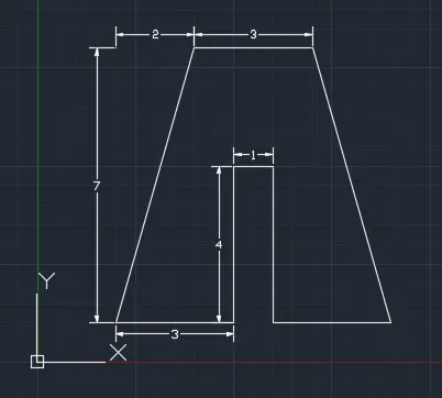
2. By using Relative rectangular method
- Select the line tool by entering L (Enter) in the command line
- Specify the starting coordinate point 1 as 2,1 in the command line
- Specify the next coordinate point 2 as @ 2,7 in command line
- Specify the next coordinate point 3 as @ 3,0 in command line
- Specify the next coordinate point 4 as @ 2,-7 in command line
- Specify the next coordinate point 5 as @ -3,0 in command line
- Specify the next coordinate point 6 as @ 0,4 in command line
- Specify the next coordinate point 7 as @ -1,0 in command line
- Specify the next coordinate point 8 as @ 0,-4 in command line
- Then click close on command line
Result:-
3. By using relative polar coordinate system
- Here the direction of angle measurement is from "East" and the orientation of angle measurement is "clock wise" direction
- Select the line tool by entering L (Enter) in the command line
- Specify the starting coordinate point 1 as 2,1 in the command line
- Specify the next coordinate point 2 as @ 7<285.9 in command line
- Specify the next coordinate point 3 as @ 3<0 in command line
- Specify the next coordinate point 4 as @ 7<74.1 in command line
- Specify the next coordinate point 5 as @ 3<180 in command line
- Specify the next coordinate point 6 as @ 4<270 in command line
- Specify the next coordinate point 7 as @ 1<180 in command line
- Specify the next coordinate point 8 as @ 4<90 in command line
- Then click close on command line
Result:-
4. By using direct distance entry method
- Select the line tool by entering L (Enter) in the command line
- Specify the starting coordinate point 1 as 2,1 in the command line
- Enter the length of the point 2 as 7 at angle 285.9 by using polar tracking from +ve x-axis
- Enter the length of the point 3 as 3 in command at +ve x-axis
- Enter the length of the point 4 as 7 at angle 74.1 by using polar tracking from +ve x-axis
- Enter the length of the point 5 as 3 in command at -ve x-axis
- Enter the length of the point 6 as 4 in command at +ve y-axis
- Enter the length of the point 7 as 1 in command at -ve x-axis
- Enter the length of the point 8 as 4 in command at -ve y-axis
- Then click close on command line
Result:-
P4
Aim:- To draft P4 geometry in AutoCAD by using Absolute coordinate system
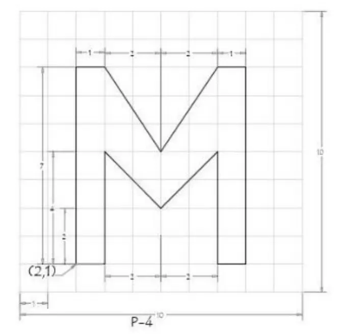
By using Absolute coordinate method
- Select the line tool by entering L (Enter) in the command line
- Specify the starting coordinate point 1 as 2,1 in the command line
- Specify the next coordinate point 2 as 2,8 in command line
- Specify the next coordinate point 3 as 3,8 in command line
- Specify the next coordinate point 4 as 5,5 in command line
- Specify the next coordinate point 5 as 7,8 in command line
- Specify the next coordinate point 6 as 8,8 in command line
- Specify the next coordinate point 7 as 8,1 in command line
- Specify the next coordinate point 8 as 7,1 in command line
- Specify the next coordinate point 9 as 7,5 in command line
- Specify the next coordinate point 10 as 5,3 in command line
- Specify the next coordinate point 11 as 3,5 in command line
- Specify the next coordinate point 12 as 3,1 in command line
- Then click close on command line
Result:-
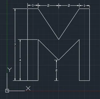
P5
Aim:- To draft P5 geometry in AutoCAD by using Absolute coordinate system
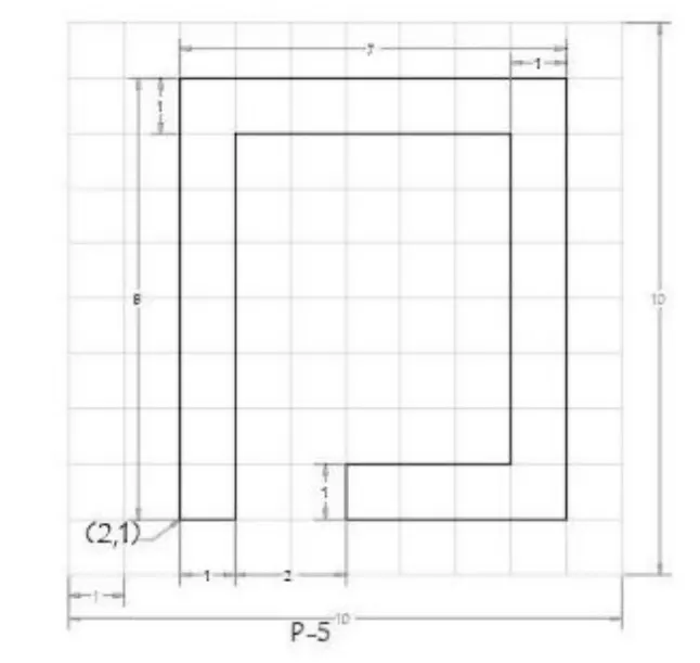
By using Absolute coordinate method
- Select the line tool by entering L (Enter) in the command line
- Specify the starting coordinate point 1 as 2,1 in the command line
- Specify the next coordinate point 2 as 2,9 in command line
- Specify the next coordinate point 3 as 9,9 in command line
- Specify the next coordinate point 4 as 9,1 in command line
- Specify the next coordinate point 5 as 5,1 in command line
- Specify the next coordinate point 6 as 5,2 in command line
- Specify the next coordinate point 7 as 8,2 in command line
- Specify the next coordinate point 8 as 8,8 in command line
- Specify the next coordinate point 9 as 3,8 in command line
- Specify the next coordinate point 10 as 3,1 in command line
- Then click close on command line
Result:-
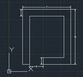
P7
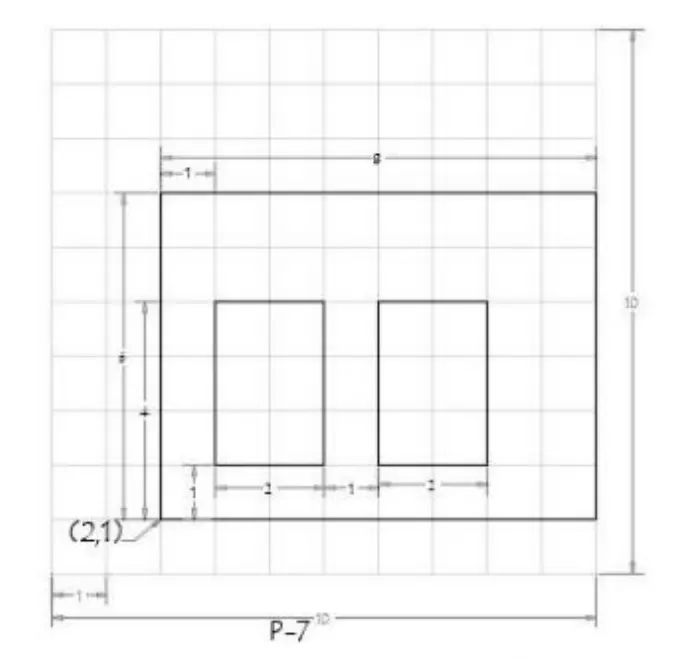
Aim:- To draft P7 geometry in AutoCAD by using Absolute coordinate system
By using Absolute coordinate method
- Select the line tool by entering L (Enter) in the command line
- Specify the starting coordinate point 1 as 2,1 in the command line
- Specify the next coordinate point 2 as 2,7 in command line
- Specify the next coordinate point 3 as 10,7 in command line
- Specify the next coordinate point 4 as 10,1 in command line
- Specify the next coordinate point 5 as 3,2 in command line
- Specify the next coordinate point 6 as 3,5 in command line
- Specify the next coordinate point 7 as 5,5 in command line
- Specify the next coordinate point 8 as 5,2 in command line
- Specify the next coordinate point 9 as 6,2 in command line
- Specify the next coordinate point 10 as 6,5 in command line
- Specify the next coordinate point 11 as 8,5 in command line
- Specify the next coordinate point 12 as 8,2 in command line
- Then click close on command line
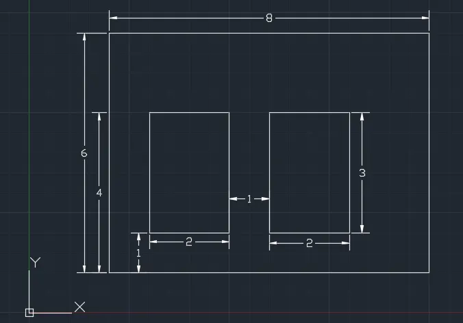
Result:-
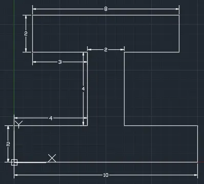
P8
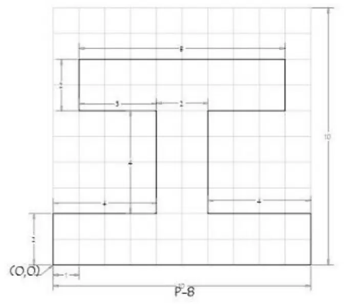
Aim:- To draft P8 geometry in AutoCAD by using Absolute coordinate system
By using Absolute coordinate method
- Select the line tool by entering L (Enter) in the command line
- Specify the starting coordinate point 1 as 0,0 in the command line
- Specify the next coordinate point 2 as 0,2 in command line
- Specify the next coordinate point 3 as 4,2 in command line
- Specify the next coordinate point 4 as 4,6 in command line
- Specify the next coordinate point 5 as 1,6 in command line
- Specify the next coordinate point 6 as 1,8 in command line
- Specify the next coordinate point 7 as 9,8 in command line
- Specify the next coordinate point 8 as 9,6 in command line
- Specify the next coordinate point 9 as 6,6 in command line
- Specify the next coordinate point 10 as 6,2 in command line
- Specify the next coordinate point 11 as 10,2 in command line
- Specify the next coordinate point 12 as 10,0 in command line
- Then click close on command line
Result:-
P9
Aim:- To draft P9 geometry in AutoCAD by using Absolute coordinate system
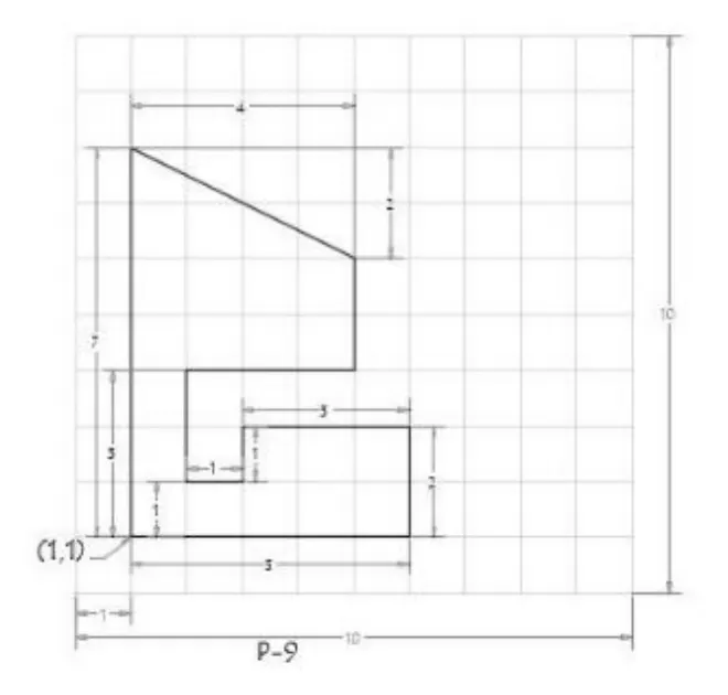
By using Absolute coordinate method
- Select the line tool by entering L (Enter) in the command line
- Specify the starting coordinate point 1 as 1,1 in the command line
- Specify the next coordinate point 2 as 1,8 in command line
- Specify the next coordinate point 3 as 5,6 in command line
- Specify the next coordinate point 4 as 5,4 in command line
- Specify the next coordinate point 5 as 2,4 in command line
- Specify the next coordinate point 6 as 2,2 in command line
- Specify the next coordinate point 7 as 3,2 in command line
- Specify the next coordinate point 8 as 3,3 in command line
- Specify the next coordinate point 9 as 6,3 in command line
- Specify the next coordinate point 10 as 6,1 in command line
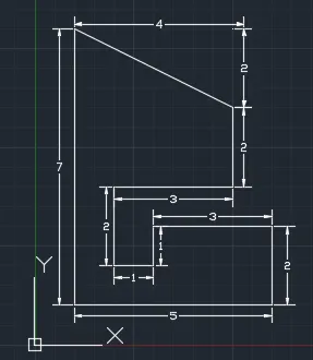
- Then click close on command line
Result:-
P10
Aim:- To draft P10 geometry in AutoCAD by using Absolute coordinate system
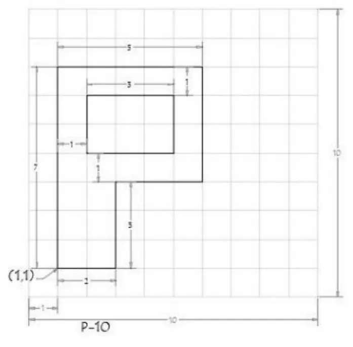
By using Absolute coordinate method
- Select the line tool by entering L (Enter) in the command line
- Specify the starting coordinate point 1 as 1,1 in the command line
- Specify the next coordinate point 2 as 1,8 in command line
- Specify the next coordinate point 3 as 6,8 in command line
- Specify the next coordinate point 4 as 6,4 in command line
- Specify the next coordinate point 5 as 3,4 in command line
- Specify the next coordinate point 6 as 3,1 in command line
- Specify the next coordinate point 7 as 2,5 in command line
- Specify the next coordinate point 8 as 2,7 in command line
- Specify the next coordinate point 9 as 5,7 in command line
- Specify the next coordinate point 10 as 5,5 in command line
- Then click close on command line
Result:-
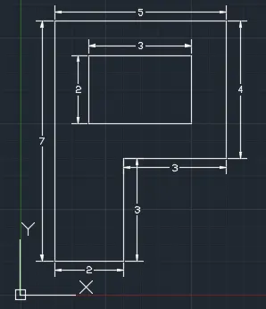
Civil related problems
Profile wood
Aim:- To draft Profile wood geometry in AutoCAD by using Absolute coordinate system
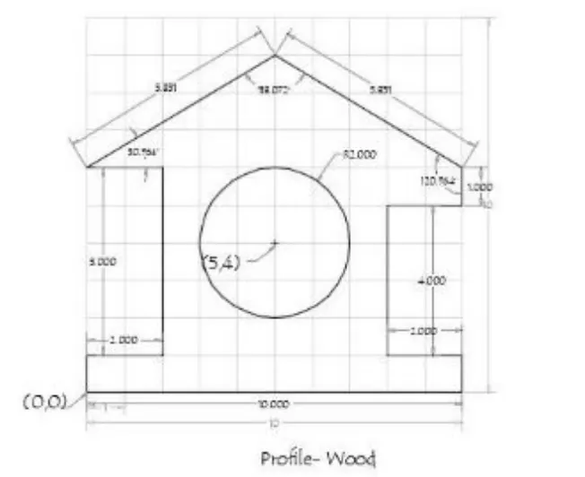
By using Absolute coordinate method
- Select the line tool by entering L (Enter) in the command line
- Specify the starting coordinate point 1 as 0,0 in the command line
- Specify the next coordinate point 2 as 0,1 in command line
- Specify the next coordinate point 3 as 2,1 in command line
- Specify the next coordinate point 4 as 2,6 in command line
- Specify the next coordinate point 5 as 0,6 in command line
- Specify the next coordinate point 6 as 5,9 in command line
- Specify the next coordinate point 7 as 10,6 in command line
- Specify the next coordinate point 8 as 10,5 in command line
- Specify the next coordinate point 9 as 8,5 in command line
- Specify the next coordinate point 10 as 8,1 in command line
- Specify the next coordinate point 11 as 10,1 in command line
- Specify the next coordinate point 12 as 10,0 in command line
- Then click close on command line
- Specify the next coordinate point 13 as 5,4 with radius 2 in command line
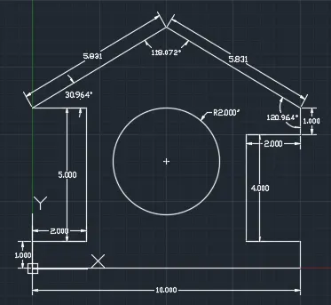
Result:-
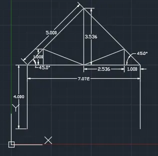
Queen post truss
Aim:- To draft Queen post truss geometry in AutoCAD by using Absolute coordinate system and polar coordinate system
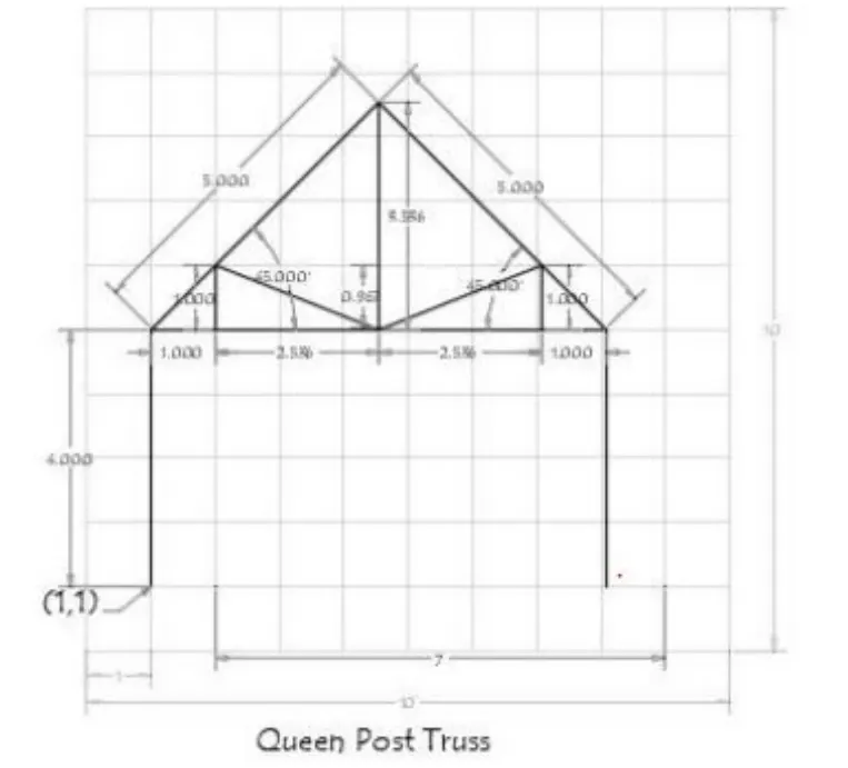
By using both Absolute coordinate method and Polar coordinate method
- Here the direction of angle measurement is from "East" and the orientation of angle measurement is "clock wise" direction
- Select the line tool by entering L (Enter) in the command line
- Specify the starting coordinate point 1 as 1,1 in the command line
- Specify the next coordinate point 2 as 1,5 in command line
- Specify the next coordinate point 3 as @5<315 in command line
- Specify the next coordinate point 4 as 1,5 in command line
- Specify the next coordinate point 5 as 2,5 in command line
- Specify the next coordinate point 6 as 2,6 in command line
- Specify the next coordinate point 7 as 2,5 in command line
- Specify the next coordinate point 8 as 4.536,5 in command line
- Specify the next coordinate point 9 as 4.536,8.536 in command line
- Specify the next coordinate point 10 as 4.536,5 in command line
- Specify the next coordinate point 11 as 7.072,5 in command line
- Specify the next coordinate point 12 as 8.072,5 in command line
- Specify the next coordinate point 13 as @5<225 in command line
- Specify the next coordinate point 14 as 7.072,5 in command line
- Specify the next coordinate point 15 as 7.072,6 in command line
- Specify the next coordinate point 16 as 4.536,5 in command line
- Specify the next coordinate point 17 as 2,6 in command line
- Specify the next coordinate point 18 as 8.072,1 in command line
Result:-
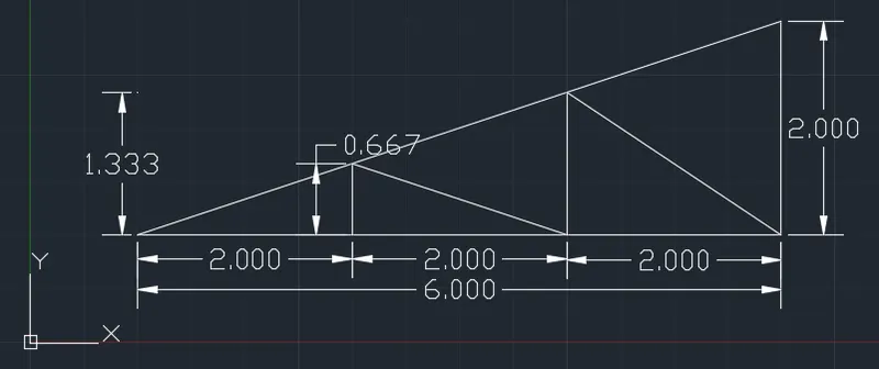
Mono pitch
Aim:- To draft Mono pitch geometry in AutoCAD by using Absolute coordinate system
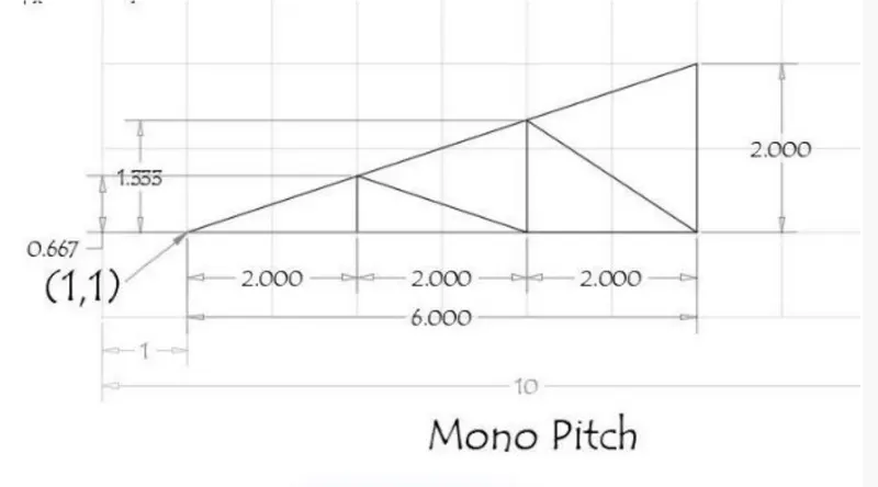
By using Absolute coordinate method
- Select the line tool by entering L (Enter) in the command line
- Specify the starting coordinate point 1 as 1,1 in the command line
- Specify the next coordinate point 2 as 7,1 in command line
- Specify the next coordinate point 3 as 7,3 in command line
- Then click close on command line
- Specify the next coordinate point 4 as 3,1 in command line
- Specify the next coordinate point 5 as 3,1.667 in command line
- Specify the next coordinate point 6 as 5,1 in command line
- Specify the next coordinate point 7 as 5,2.333 in command line
- Specify the next coordinate point 8 as 7,1 in command line
Result:-