Creating a Floor plan, Footing detail and Isometric view using AutoCad
Aim:- To draft the floor plan, footing details and isometric view using AutoCAD
Introduction:
Floor Plan
- Floor plan is a type of drawing that shows the layout of a home or property from above
- Planning of a building gives the idea about the building how the building will be done in future
- Planning plays an important role in the civil engineering because without this planning we can't determine structural element
- Planning may be residential, public or commercial building
Footing details
- Footing reinforcement details depends on the design
- Footing depth and width are depend on the soil bearing capacity
There are 2 types of foundation
- Shallow foundation
- Deep foundation
Shallow foundation are of 5 types they are
- Isolated footing
- Combined footing
- Strip footing
- Strap footing
- Raft or Mat footing
Deep foundation are of 2 types they are
- Pile foundation
- Drilled shaft or caissons
Isometric view:-
Isometric projection/view is a method for visually representing three dimensional object in two dimension in engineering drawings
or
Isometric drawing is a 3D representation of an object on 2D surface
Procedure:-
- Go to start menu, click on Start drawing
- Type stratup (Enter) in command line
- Enter the new value of start up:1
- Go to application menu and select new or type new in command line
- In the "create new drawing" dialogue box contains imperial type of systems and metric type of system
- We select the metric system in the "start from scratch" option
- After that in Advance setup option select the decimal unit system in the units
The above procedure should be followed every time when the new sheet is opened
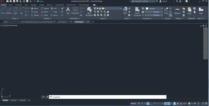
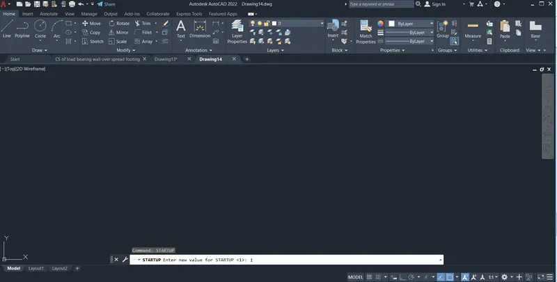
Entering the start up command in the command line Entering the value 1 for the start up
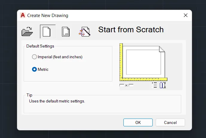
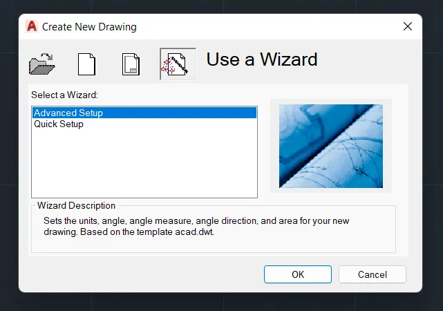
When we go to the new file then we get this file Then advance setup setting should be done by clicking OK
select the metric from start from scratch
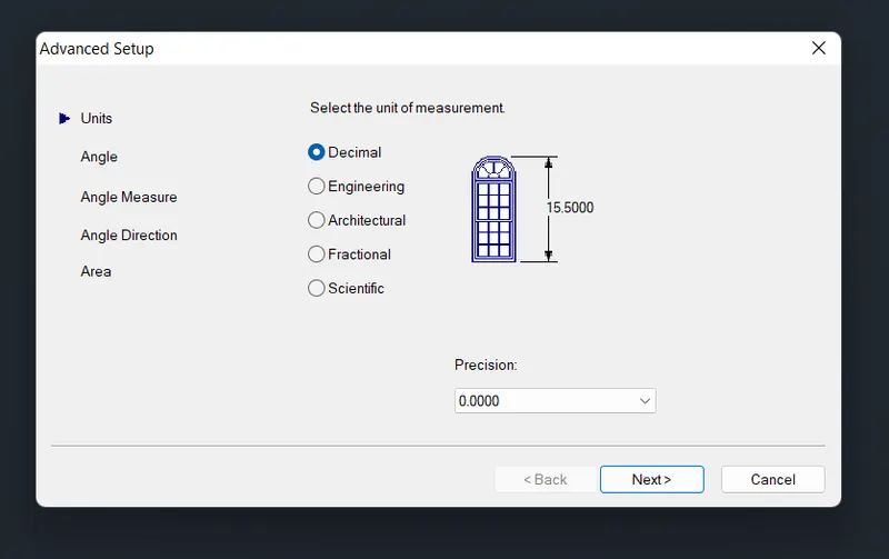
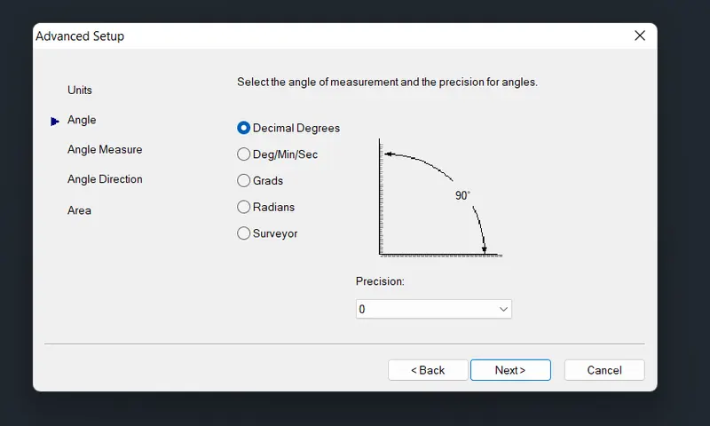
Keep the units in decimal and adjust precision then click next Keep angle in decimal degree and adjust precision then OK
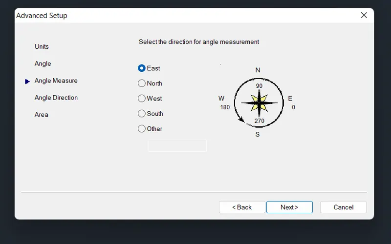
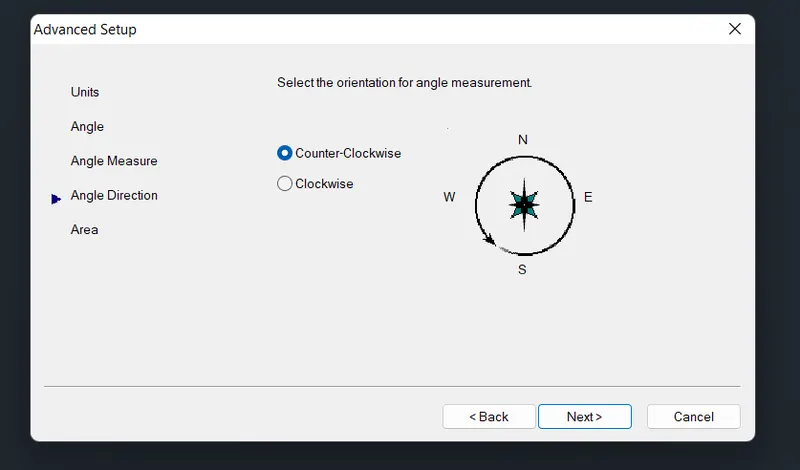
Select the angle measurement in east Select angle direction in counter clockwise
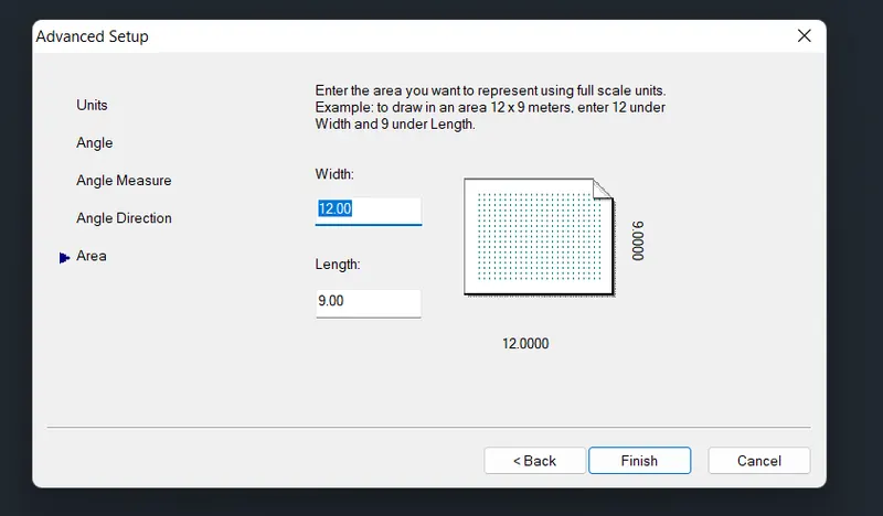
Keep the width as 12m and length of 9m as default and click on finish
Creating floor plan, footing details and isometric view using AutoCAD
Aim:- To draft cross section of load bearing wall over spread footing
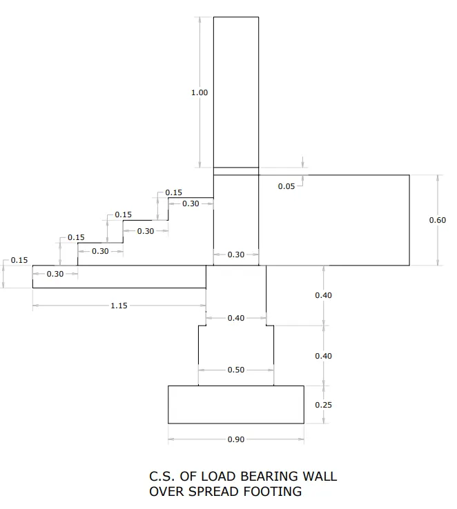
By using direct distance entry method
- Here all the units are in metric
- Select the line tool by entering L (Enter) in the command line
- Specify the starting point 1 any where in the screen
- Enter the length of the point 2 as 0.90 in command at +ve x-axis
- Enter the length of the point 3 as 0.25 in command at +ve y-axis
- Enter the length of the point 4 as 0.20 in command at -ve x-axis
- Enter the length of the point 5 as 0.40 in command at +ve y-axis
- Enter the length of the point 6 as 0.05 in command at -ve x-axis
- Enter the length of the point 7 as 0.40 in command at +ve y-axis
- Enter the length of the point 8 as 0.05 in command at -ve x-axis
- Enter the length of the point 9 as 0.60 in command at +ve y-axis
- Enter the length of the point 10 as 0.05 in command at +ve y-axis
- Enter the length of the point 11 as 1 in command at +ve y-axis
- Enter the length of the point 12 as 0.30 in command at -ve x-axis
- Enter the length of the point 13 as 1 in command at -ve y-axis
- Enter the length of the point 14 as 0.05 in command at -ve y-axis
- Enter the length of the point 15 as 0.60 in command at -ve y-axis
- Enter the length of the point 16 as 0.05 in command at -ve x-axis
- Enter the length of the point 17 as 0.40 in command at -ve y-axis
- Enter the length of the point 18 as 0.05 in command at -ve x-axis
- Enter the length of the point 19 as 0.40 in command at -ve y-axis
- Enter the length of the point 20 as 0.20 in command at -ve x-axis
- Enter the length of the point 21 as 0.25 in command at -ve y-axis
- Then click close on command line
- Enter the length of the point 22as 0.15 in command at -ve y-axis
- Enter the length of the point 23 as 1.15in command at -ve x-axis
- Enter the length of the point 24 as 0.15 in command at +ve y-axis
- Then click close on command line
- Enter the length of the point 25 as 0.30 in command at +ve x-axis
- Enter the length of the point 26 as 0.15 in command at +ve y-axis
- Enter the length of the point 27 as 0.30 in command at +ve x-axis
- Enter the length of the point 28 as 0.15 in command at +ve y-axis
- Enter the length of the point 29 as 0.30 in command at +ve x-axis
- Enter the length of the point 30 as 0.15 in command at +ve y-axis
- Enter the length of the point 31 as 0.85 in command at +ve x-axis
- Enter the length of the point 32 as 0.60 in command at +ve y-axis
- Then click close on command line
Result:-
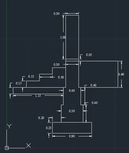
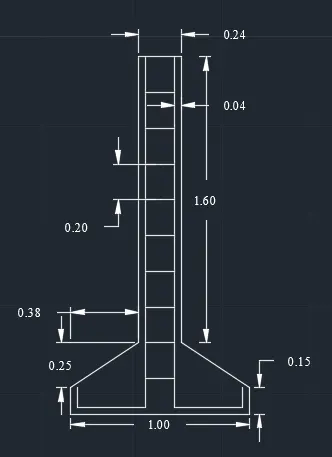
Aim:- To draft the cross section of isolated footing
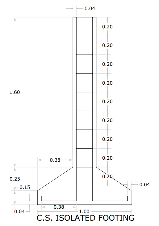
By using direct distance entry method
- Here all the units are in metric
- Select the line tool by entering L (Enter) in the command line
- Specify the starting point 1 any where in the screen
- Enter the length of the point 2 as 1 in command at +ve x-axis
- Enter the length of the point 3 as 0.15 in command at +ve y-axis
- To draw the inclination line draw a random line from the mid of point 2 line which has a distance of 1 and draw the line of 0.25 from 0.15 in +y-axis the same line is use to draw a 0.38 line in +x-axis then join the line from upper point of 0.15 to ending point of 0.38 then we get the point 4
- Enter the length of the point 5 as 1.60 in command at +ve y-axis
- Enter the length of the point 6 as 0.24 in command at +ve x-axis
- Enter the length of the point 7 as 1.60 in command at -ve y-axis
- To draw the inclination line draw a random line from the mid of point 2 line which has a distance of 1 and draw the line of 0.25 from 0.15 in +y-axis the same line is use to draw a 0.38 line in -x-axis then join the line from upper point of 0.15 to ending point of 0.38 then we get the point 8
- Take a cover of 0.04 at the bottom bothside and draw a line of 0.38 and extend upto the top
- Take a cover of 0.0.4 at the top also and take a offset option and do the offset of 0.20 till the bottom
Result:-
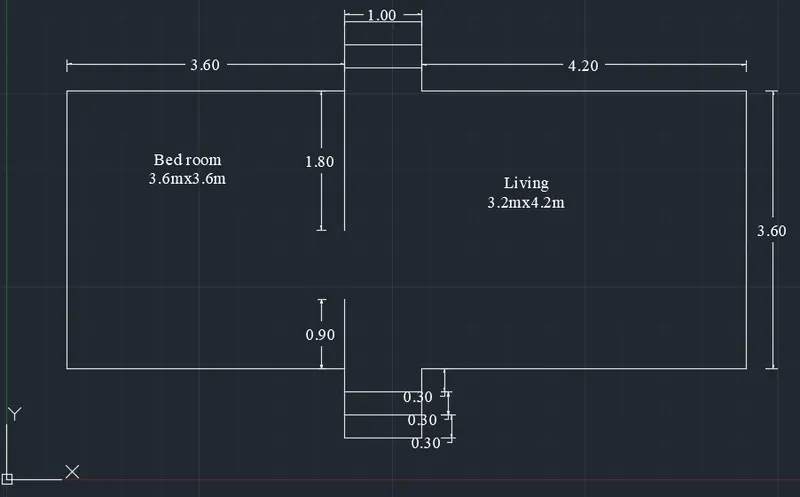
Aim:- To draft the line diagram of two bed room building
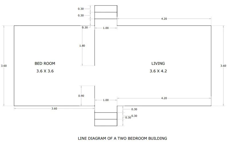
By using direct distance entry method
- Here all the units are in metric
- Select the line tool by entering L (Enter) in the command line
- Specify the starting point 1 any where in the screen
- Enter the length of the point 2 as 3.60 in command at -ve x-axis
- Enter the length of the point 3 as 3.60 in command at +ve y-axis
- Enter the length of the point 4 as 3.60 in command at +ve x-axis
- Enter the length of the point 5 as 0.30 in command at +ve y-axis
- Enter the length of the point 6 as 0.30 in command at +ve y-axis
- Enter the length of the point 7 as 0.30 in command at +ve y-axis
- Enter the length of the point 8 as 1 in command at +ve x-axis
- Enter the length of the point 9 as 0.30 in command at -ve y-axis
- Enter the length of the point 10 as 0.30 in command at -ve y-axis
- Enter the length of the point 11as 0.30 in command at -ve y-axis
- Enter the length of the point 12as 1 in command at +ve x-axis
- Enter the length of the point 13 as 1 in command at +ve x-axis
- Enter the length of the point 14 as 4.20 in command at +ve x-axis
- Enter the length of the point 15 as 3.60 in command at -ve y-axis
- Enter the length of the point 16 as 4.20 in command at -ve x-axis
- Enter the length of the point 17 as 0.30 in command at -ve y-axis
- Enter the length of the point 18 as 0.30 in command at -ve y-axis
- Enter the length of the point 19 as 0.30 in command at -ve y-axis
- Enter the length of the point 20 as 1 in command at -ve x-axis
- Enter the length of the point 21 as 0.30 in command at +ve y-axis
- Enter the length of the point 22 as 0.30 in command at +ve y-axis
- Enter the length of the point 23 as 0.30 in command at +ve y-axis
- Enter the length of the point 24 as 1 in command at +ve x-axis
- Enter the length of the point 25 as 1 in command at +ve x-axis
- Enter the length of the point 26 to inside the building as 0.90 in command at +ve y-axis
- Enter the length of the point 27 to inside the building as 1.80 in command at -ve y-axis
Result:-
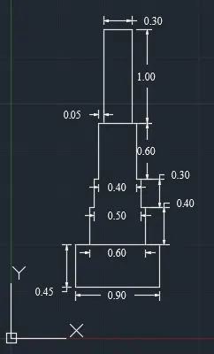
Aim:- To draft the cross section of load bearing wall showing foundation details
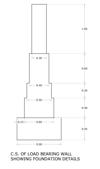
By using direct distance entry method
- Here all the units are in metric
- Select the line tool by entering L (Enter) in the command line
- Specify the starting point 1 any where in the screen
- Enter the length of the point 2 as 0.90 in command at +ve x-axis
- Enter the length of the point 3 as 0.45 in command at +ve y-axis
- Enter the length of the point 4 as 0.15 in command at -ve x-axis
- Then click close on command line
- Enter the length of the point 5 as 0.40 in command at +ve y-axis from the point 4 of 0.15 ending point
- Enter the length of the point 6 as 0.05 in command at -ve x-axis
- Enter the length of the point 7 as 0.30 in command at +ve y-axis
- Enter the length of the point 8 as 0.05 in command at -ve x-axis
- Enter the length of the point 9 as 0.60 in command at +ve y-axis
- Enter the length of the point 10 as 0.40 in command at -ve x-axis
- Enter the length of the point 11 as 0.60 in command at -ve y-axis
- Enter the length of the point 12 as 0.05 in command at -ve x-axis
- Enter the length of the point 13 as 0.30 in command at -ve y-axis
- Enter the length of the point 14 as 0.05 in command at -ve x-axis
- Enter the length of the point 15 as 0.40 in command at -ve y-axis
- Enter the length of the point 16 as 0.05 in command at -ve x-axis from the starting point of point 10 of 0.40
- Enter the length of the point 17 as 1 in command at +ve y-axis
- Enter the length of the point 18 as 0.30 in command at -ve x-axis
- Enter the length of the point 19 as 1 in command at -ve y-axis
- Enter the length of the point 20 as 0.05 in command at -ve x-axis from the ending point of point 10 of 0.40
Result:-
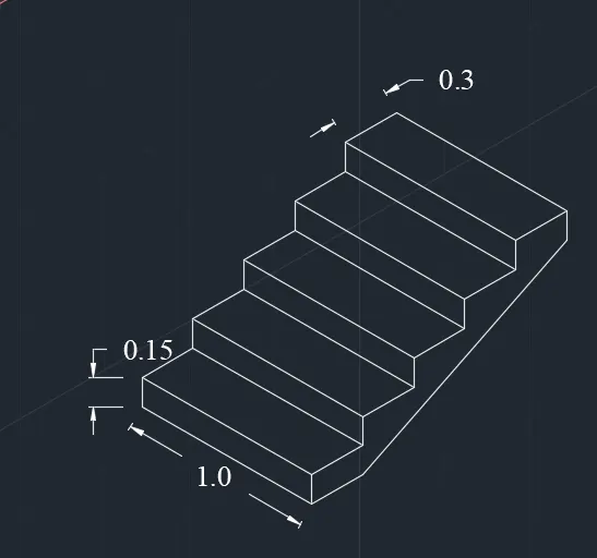
Aim:- To draft the Isometric view of steps
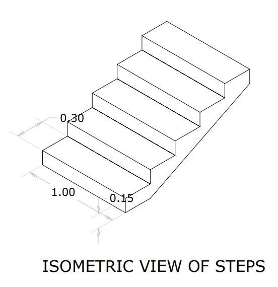
By using direct distance entry method
- Here all the units are in metric
- Select the line tool by entering L (Enter) in the command line
- Switch on the ortho mode and isometric drafting
- Take a isoplane left
- Specify the starting point 1 any where in the screen
- Enter the length of the point 2 as 1 in command at +ve y-axis
- Enter the length of the point 3 as 0.15in command at +ve z-axis
- Enter the length of the point 4 as 1 in command at -ve y-axis
- Then click close on command line
- Take a isolane right
- Enter the length from the point 3 as 0.3 in command at +ve x-axis is a point 5
- Take a isoplane left
- Enter the length from the point 6 as 1 in command at -ve y-axis
- Take a isolane right
- Enter the length from the point 4 as 0.3 in command at +ve x-axis is a point 7
- Select all then copy the single step and switch off the ortho mode
- Place the single step one on one to get a 5 steps
- Swith on the ortho mode
- Draw a line of 0.30 at the bottom of the 1st step at +ve x-axis and draw a line of 0.15 at bottom of the 5th step at -ve z-axis
- Swith off the ortho mode and connect these two lines
Result:-
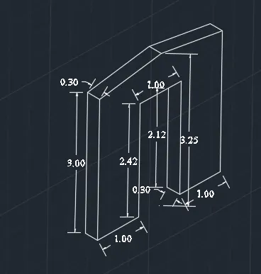
Aim:- To draft the Isometric view of Gable wall
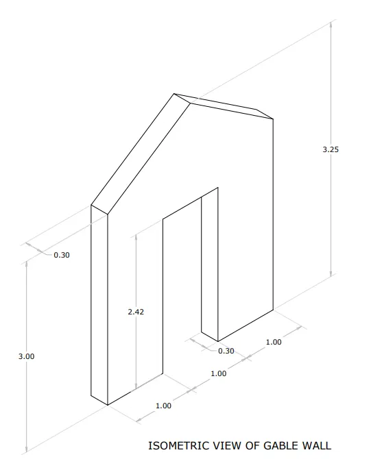
By using direct distance entry method
- Here all the units are in metric
- Select the line tool by entering L (Enter) in the command line
- Switch on the ortho mode and isometric drafting
- Take a isoplane right
- Specify the starting point 1 any where in the screen
- Enter the length of the point 2 as 1 in command at +ve x-axis
- Enter the length of the point 3 as 2.42 in command at +ve z-axis
- Enter the length of the point 4 as 1 in command at +ve x-axis
- Enter the length of the point 5 as 2.42 in command at -ve z-axis
- Enter the length of the point 6 as 1 in command at +ve x-axis
- Enter the length of the point 7 as 3 in command at +ve z-axis
- Enter the length of the point 8 as 3 in command at +ve z-axis
- Take a isoplane left
- Enter the length of the point 9 as 0.3 in command at +ve y-axis
- Enter the length of the point 10 as 3 in command at +ve z-axis
- Enter the length of the point 11 as 0.3 in command at -ve y-axis
- Enter the length of the point 12 as 0.3 in command at +ve y-axis which is a door thickness
- Enter the length of the point 13 as 2.12 in command at +ve z-axis
- To draw the inclination drawing draw the horizontal line at the bottom of the door and draw a perpendicular line from the horizontal line at the distace of 3.25 at +ve z-axis
- Join the line at the both the sides then we get the point 14
- Enter the length of the point 15 as 0.3 in command for thickness at the mid of inclination above the door at +ve y-axis
- Join the thickness line both the sides then we get the point 16
Result:-