Creating Levels, Grids, Layout and model elements for a residential unit using REVIT
1. What is BIM? Summarize the features of BIM and benefits of using BIM over 2D CAD tools.
BIM:- Building information modelling is a visual representation of physical and functional characteristic of a facility from the begining
- It serves as a shared information repository collaboration throughout a facilities life cycle
- It is used by Architects, Structural Engineer's, Electric and Plumbing department etc.,
- BIM is a process for 3D visualisation and it's not a software
Features of BIM
- Easy access to information :-It is the physical and functional characteristic of the building process that provides very minute information about the project
- Making the process more expressive :- CAD softwares allows the users to work in 3 dimension length, breadth and depth but BIM allows user to work in 5 dimensions like length, breadth, depth, time and cost
- Comprehensive view of the project :- BIM does not only include 3D view of the structure they provide a comprehensive over view of the entire building process
Benefits of the BIM
- Complete representation :- It provide each and every representation and it will take a whole components of a building to account
- Instant update:-BIM allows the user to instant updates of all the objects
- Time constraint:-BIM model allow you to prefabricate important components ahead of time
- Resource tracking:- By using this our clients can see the update of the project easily when ever they need
2. Understand the concept of Categories, Families, Elements, Instances in Revit. Go to Insert Tab, choose a category. Pick a family and element. Understand the instances and insert it to Revit model
Categories
- The properties in Revit that are already present and properties are predefined by the softwares
- Ex:- Doors, Windows, Walls etc.,
Families
- Group of elements that shares a common property
- Ex:- In the doors we see the Single flush door which consists of a different dimension doors (elements) this are called families
Type
- It is the specific representation in a family defined by distinct parametric, graphical and documentation characteristic which makes other types in the family
- Ex:- When you select the door element then you get a specify type dialouge box it consists of a different types, width and height respectively. This is called as type
Instants or Elements
- The family which includes different dimension model are called Elements
- Ex:- The single flush door consists of 30"x80", 30"x84", 32"x84", etc., these are elements
3.
Aim:- Setting up a Project – Open a project file with architectural template. Save the file with appropriate name. Set up the project units to Imperial / Metric based on your convenience of modelling. Complete the project information under Manage tab. Set up the maximum backups for project file to 3
Introduction:-
Project information :- Its the information required to enter into the templates of our project which includes
- Organisation name
- Organisation description
- Builidng name
- Author
- Project date and status
- Client name
- Project address, Project name, Project number
Procedure:-
Step1:-
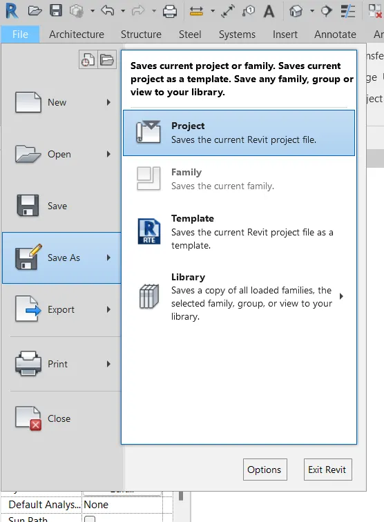
- First save the file by Save as
- Go to file menu then click on save as
- Then click on project
Step2:-
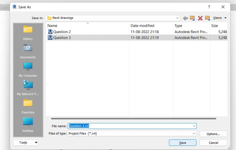
- After clicking on project then save as dialouge box opens
- Give the file name as your wish
- Then click on save
Step3:-
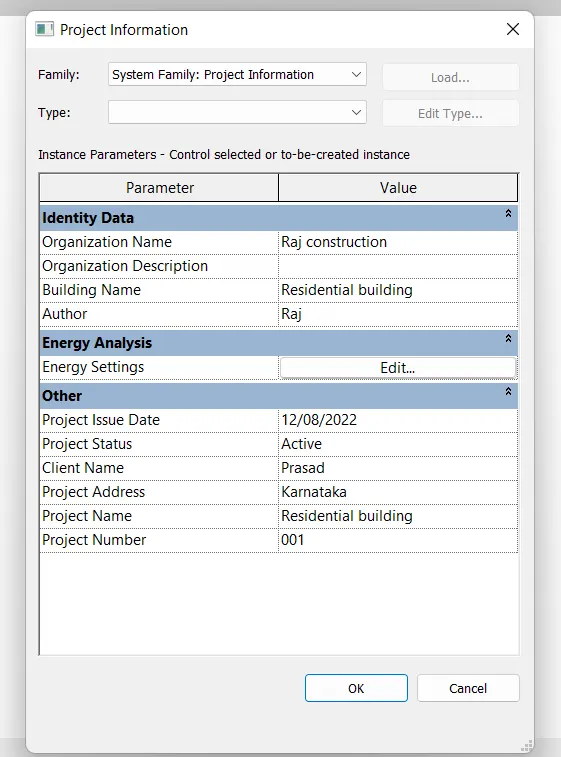
- Go to the manage tool
- Then click on the Project information menu
- Give the information that requires to the project
- After entering the information click on OK
Step4:-
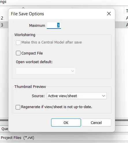
- To give a maximum back up 3
- Go to the save as option then click on the option which is near the save option
- Then this dialouge box opens
- In default maximum number of back up is 3, keep it as it is then click on OK
- At last click on Save
Result:-
Project information
- Organisation name
- Organisation description
- Builidng name
- Author
- Project date and status
- Client name
- Project address, Project name, Project number
This is the project information that require for this building model
This is the maximum back up number that require for this building model
4.
Aim:- Understand the concept of Levels and Grids. Follow the naming and conventions. Create the following Levels: ( Convert to metric equivalents if metric is your units)
Ground Floor @ 0’
First Floor @ 10’
Second Floor @ 20’
Roof @ 30’
Introduction:-
Levels :-It is used to indicate the distance/ height of the foundation, roof in the elevation and esction of a building
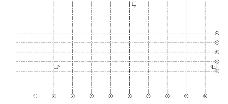
Grids:- It is used to place the columns and walls and It is also used to take a center to center distance between the columns and walls
Procedure:-
Step 1:-
- Open the new project file in Revit
- Then go for elevation (East) to create the levels
- In default there are 2 levels are present
- To create more number of levels click on level
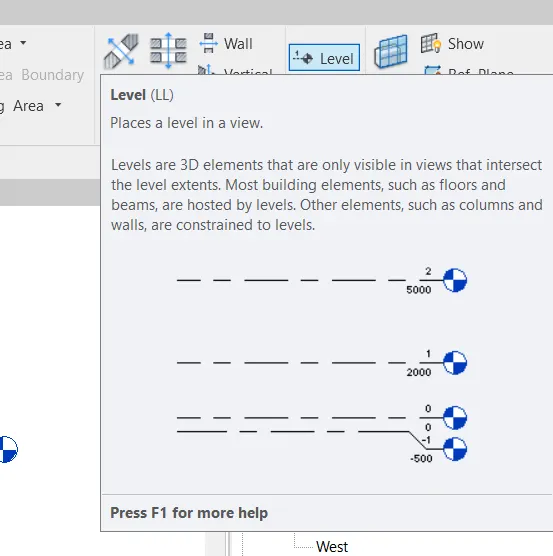
Step 2:-
- After clicking on levels the modify menu opens
- Click either lines or pick lines here the pick line option is selected
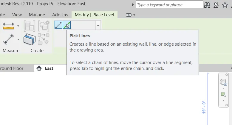
Step3:-
- In default level 1 and level 2 lines are present
- The distance between the level 1 and level 2 is 10'-0"
- Mention the offset distance 10'-0" then keep on clicking the level lines
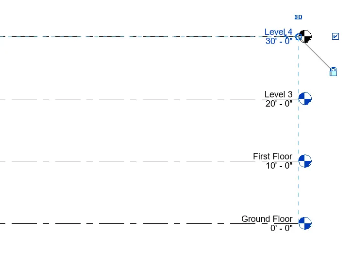
Step 4:-
- After marking the leveling
- Then change the name from level 1 to Ground Floor, level 2 to First Floor, level 3 to Second Floor, level 4 to Roof
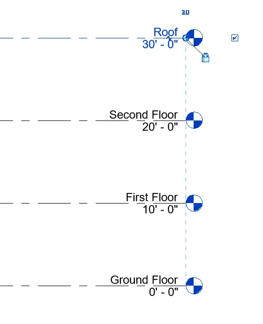
Step 5:-
- After leveling mark the grid line for the project
- Go to the architecture tab
- Then click on the grid which is present below the levels
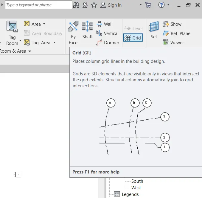
Step 6:-
- After clicking on grids the modify menu opens
- Click either lines or pick lines here the pick line option is selected
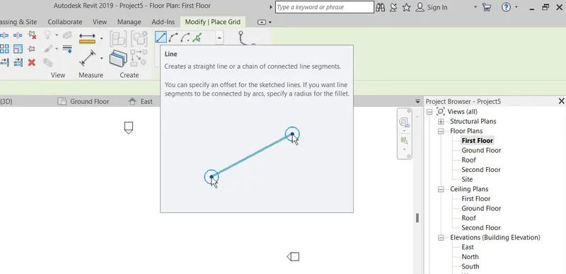
Step7:-
- First draw a line by using a line option to creating a grids
- Then select a pick line option the transverse and longitudinal grids are created here
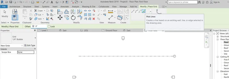
Step 8:-
- Click on the pick line option
- The transvers lines should be at 10' spacing
- Draw a grid line in horizontal direction
- Give a offset value as 10'
- Then click on the lines from top to bottom then we will get the grid lines as like this
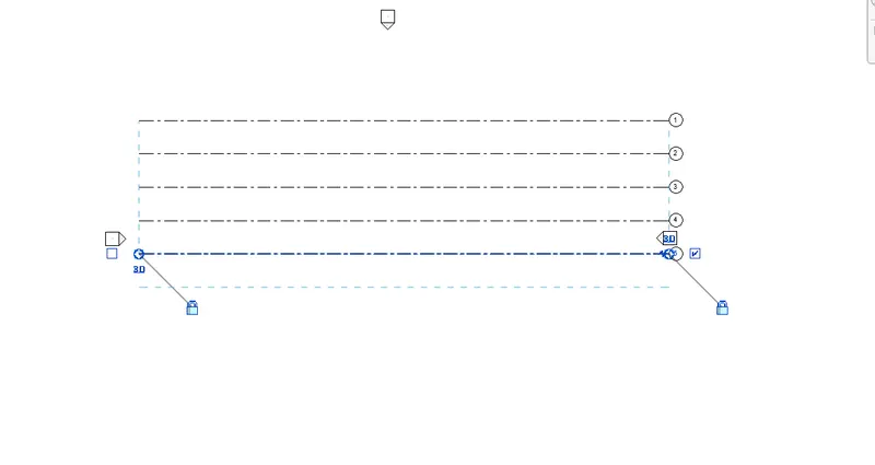
Step 9:-
- Click on the pick line option
- The longitudinal lines should be at 20' spacing
- Draw a grid line in vertical direction
- Give a offset value as 20'
- Then click on the lines from left to right then we will get the grid lines as like this
Result:-
This is the renamed or updated levels for the building model
This is the renamed or updated grid lines for the building model
5.
Aim:- 3D modelling of residential unit – From looking at your house / or a place you aspire. Create a conceptual layout of the residential unit. You can measure using a tape or
you can access your residential plan to create a similar layout.
Floor Plan
- Floor plan is a type of drawing that shows the layout of a home or property from above
- Planning of a building gives the idea about the building how the building will be done in future
- Planning plays an important role in the civil engineering because without this planning we can't determine structural element
- Planning may be residential, public or commercial building
Procedure:-
Step1:-
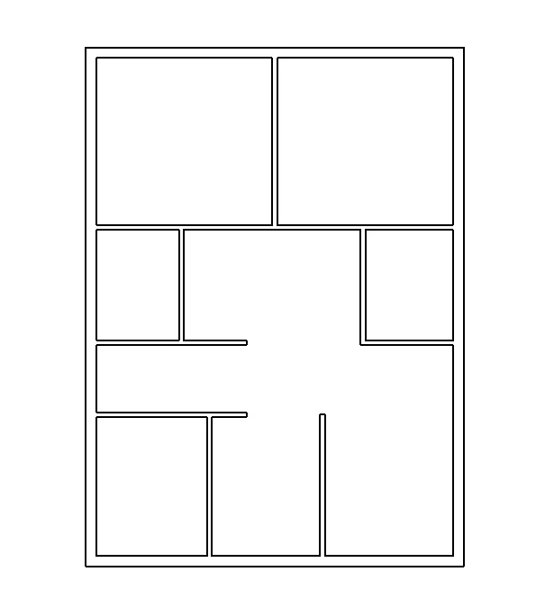
- The wall is creating by using a line
- In default the size of the wall is 8" Generic
- The exterior wall size is 9" and interior wall size is 4"
- This building consists of a 2 bedrooms, 2 attach bathroom, Kitchen, Dining, Living, Passage.
Step 2:-
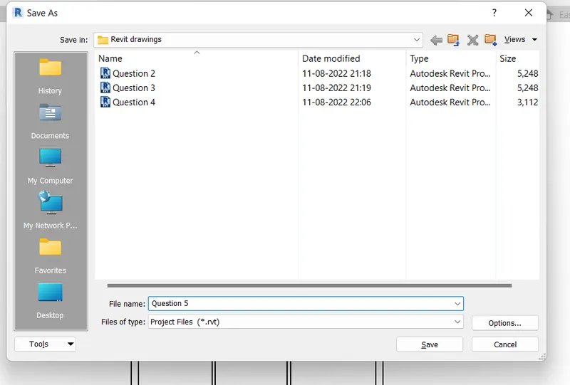
- After creating the wall then save it by using a save as option
- Click on file go to save as then click on project
- After clicking into the project the save as dialauge box opens
- Save the project by giving the appropriate name for the model
Step3:-
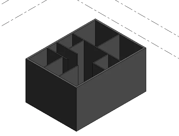
- To get this 3D view
- Click on the 3D view which is in the view tab
- Then click on the realistic in the visual style
Result:-
This is the 3D modelling residential unit
6.
Aim:- In the layout created draft the level of details you are planning to include – Dimensions of room, components you plan to add in the residential unit.
Introduction:-
- Dimension is one of the important parameter which mmeasures the distance from wall to wall or center of column to another center of column and other elements
Procedure:-
Step1:-
- To provide the dimensions for the building
- Go to annotate tab then you will get the aligned, linear and angular option
- Click on the linear dimension to measure the building
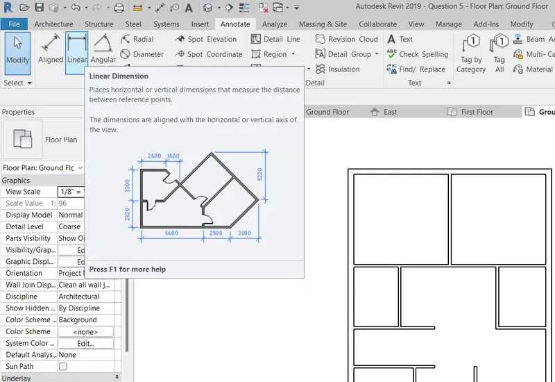
Step2:-
- After selecting into the linear option
- Click on the wall carefully where the blue dot are appears
- Adjust the dimension bubble to give inner to inner or outer to outer dimension
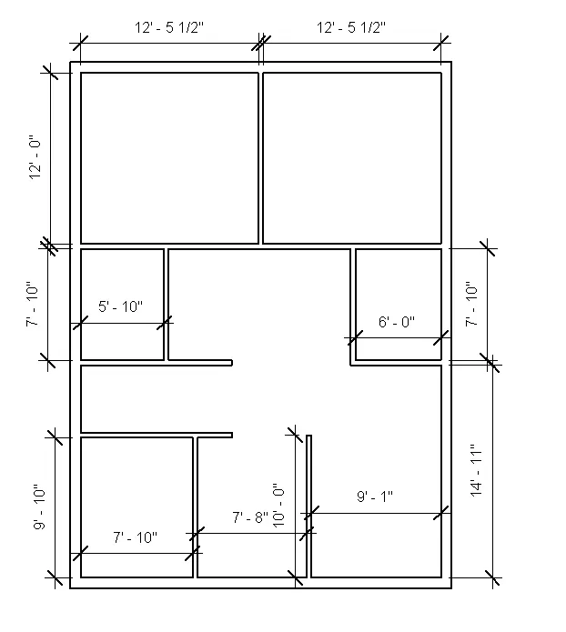
Result:-
This is the dimensioned residential unit layout
7.
Aim:- Identify the residential model elements such as Door, Windows, Tables, Chair, Couch, Bed, Lamps from the library and insert them to the model . Save the project for use
for Assignment 3
Procedure:-
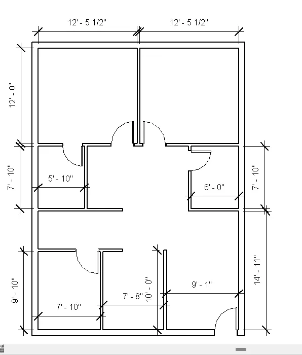
Step 1:-
- To assign the doors, windows, tables, chairs, beds, lamps we should take it from the load family which is predefined by the Autodesk Revit
- Here doors, windows, tables, chairs, beds, lamps are categories
- The differnt types of doors, windows, tables, chairs, beds, lamps are families
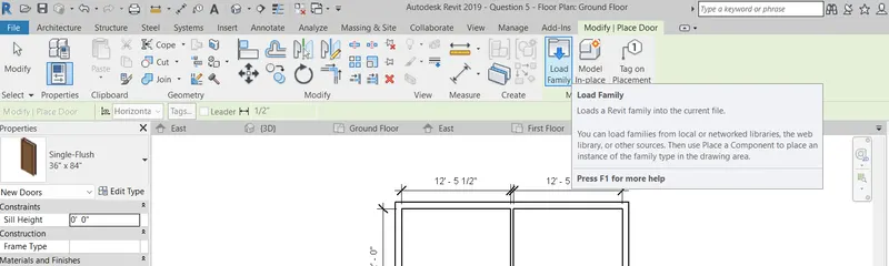
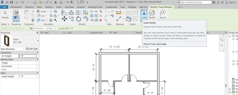
Step2:-
- Select the door in architecture then go to the load family
- This is the path of a family for doors
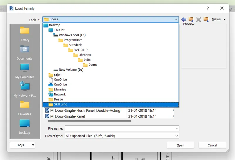
Step3:-
- Assign the main doors at the entry door, bedrooms
- Assign the single flush doors in the attch bathrooms and kitchen region
Step 4:-
- To assign the doors, windows, tables, chairs, beds, lamps we should take it from the load family which is predefined by the Autodesk Revit
- Here doors, windows, tables, chairs, beds, lamps are categories
- The differnt types of doors, windows, tables, chairs, beds, lamps are families
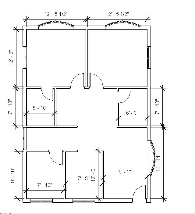
Step5:-
- Assign the large windows at the living and bedrooms
- Assign the smaller windows in the bedroom, passage, dining and kitchen region
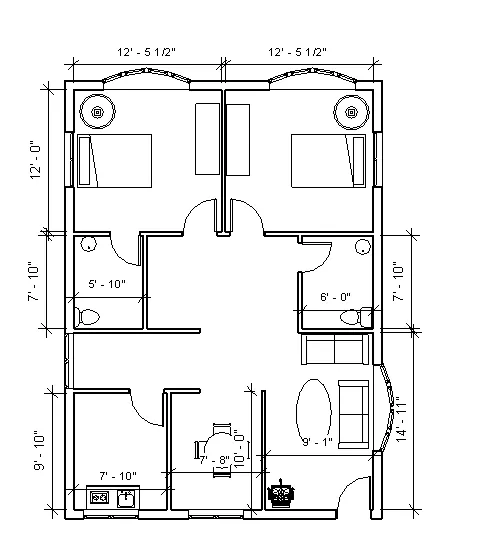
Step 6:-
- Assign the furnitures like tables, chairs, couch, beds, lamps
- Go to the load family and findout their category then you will get this inbuilt elements
- All the elemants are placed with their respective places
Step7:-
- To get this 3D view
- Click on the 3D view which is in the view tab
- Then click on the realistic in the visual style
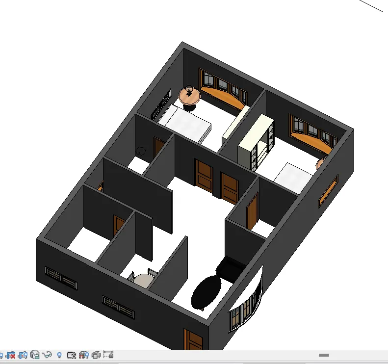
Result:-
This is the 3D view of the building along with doors, windows, furnitures