Reinforcement detailing of Columns from ETABS output
Introduction:-
Seismic force :- It is the external force applied to the structure as a result earthquake generated agitation
- In this the earthquake occured at once in a 2500 years
- Seismic cannot be determined it's a less uncertainity
- Seismic force occure at the ground level in all the directions and it has 3degree of freedom they are 2 translational and 1 rotational force
- The base shear starts at the bottom of the buildings when the seismic load occures
ETABS :-
- The full form of ETABS is Extended three dimensional analysis of building system
- ETABS software was started by CSI (Computers and Structural ,Inc
- ETABS is a engineering software which is used for multistorey analysis and design
- In this software we can analyse and design the seismic load, wind load, and other loads
- In this software we are defining and assigning the materials, frame sections, slab sections diaphragm etc.,
- This software give the proper output result to that analysed model
- In this question the model is given in the question itself so we need to analyse and design the frame structures
- By using an AutoCAD draw the detailing of the column
Column:-
- Column is a structural element which carry heavy load in the buildings
- Column may take the load or may not take the load because we have 2 types of column architectural column and structural column
- Architectural column doesnot take loads
- Structural column takes heavy load in the buildings
- Columns may be square or rectangular or circular in shape
Procedure:-
Step1:-
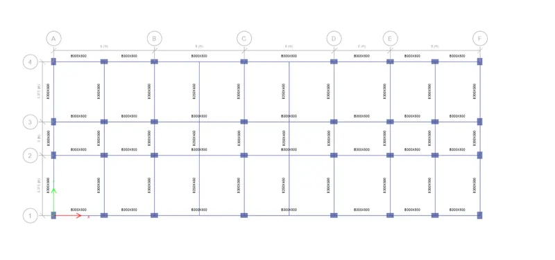
- This model is given in the question itself
- Open this model by using a ETABS
Step2:-
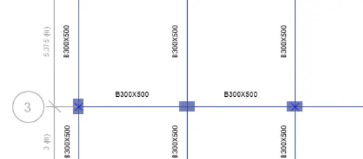
- After opening the model then select the column
- To select the column drag a mouse then the column will be selected
Step3:-
- After selecting the 2 columns
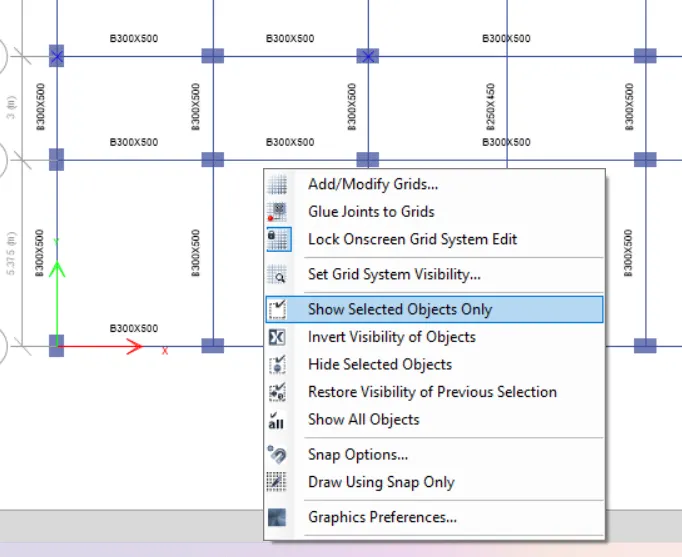
- Then click a right button of your mouse
- Then click on the show selected objects only
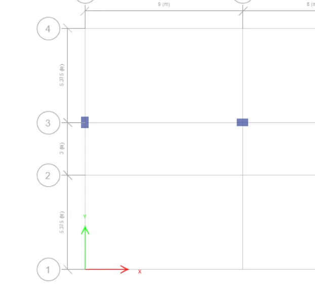
- Then the selected column only appear in the screen the snap shot is inserted below
Step4:-
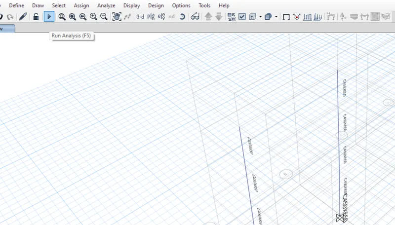
- After selecting the column then click on Run analysis
- Click on Run analysis or use a F5
- Make sure that the correct column is selected which has given in the question
Step5:-
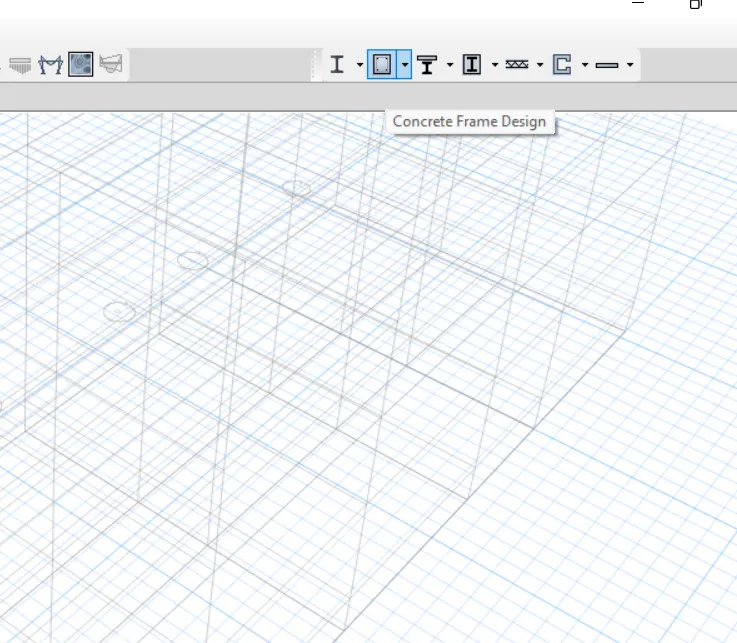
- After the analysis complete then go to the concret frame design
- Click on the concrete frame design
- Then wait for some times then it will show the details of the model
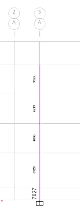
Lateral reinforcement and shear reinforcement of column at Grid A-3
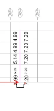
Lateral reinforcement and shear reinforcement of column at Grid B-3
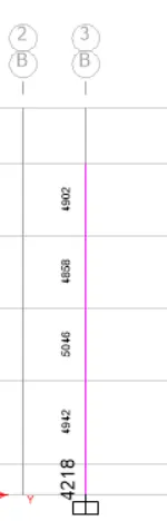
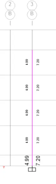
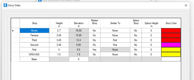
Storey assignment tab to refer elevation of column
Special confining reinforcement from IS 13920-2016 (Clause 8.1)
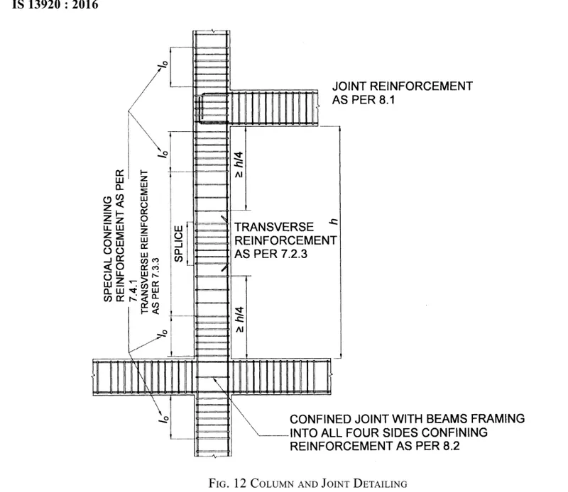
From the IS 13920-2016 mentioned about the lo , confinement spacing and amount of confinement rebar
lo not less than
- Larger column dimension
- 1/6th of the clear span of the column
- 450mm
Here the lerger column dimension is 650mm
In the 1/6th of clear span
- Column size is given as 450x650mm
- In this I'm considering firt floor height which is a 4m
- The height is given from the center of the column to the center of the other column
- We have to deduct the half of the beam depth
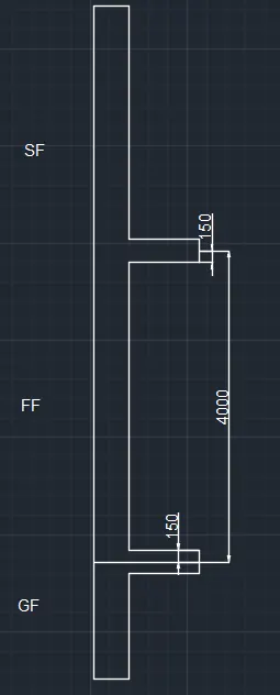
- Deduct the 150mm above and below ass shown in fig then we get the height of the column as 3700
- 1/6 * 3700 = 616mm
In this we have to take a heighest value so take a 650mm which is a larger column dimension
Confinement spacing
Confinement spacing not more than
- 1/4 of smaller column dimension
1/4*450 = 112.5
- 6 times dia of the column
6*8 = 48
- 100mm
Column 450x650mm which I have provided the 25mm dia bar throughout the column
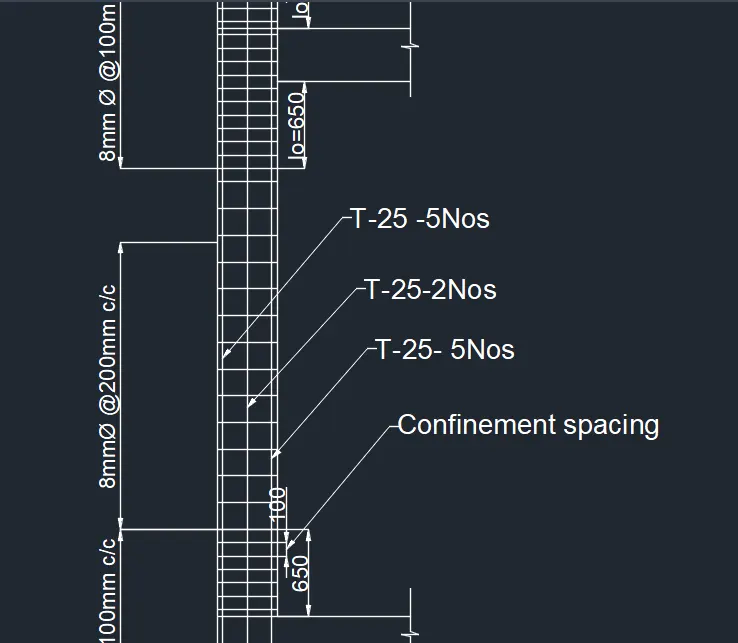
This is the snap shot for 1 floor which I have provided the 25mm dia bar throughout the column
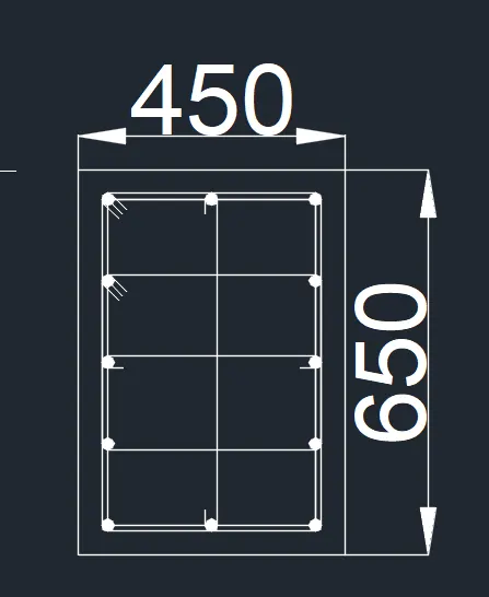
Cross section of column which I have provided the 25mm dia bar throughout the column
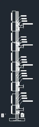
longitudinal section of column which I have provided the 25mm dia bar throughout the column
Column 450x650mm which I have provided the 32mm and 25mm dia bar at the column in 450mm direction
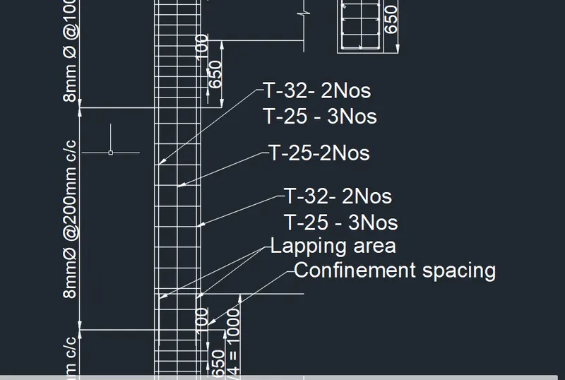
This is the snap shot for 1 floor which I have provided the 32mm and 25mm dia bar the lapping area occured at the column in 450mm direction
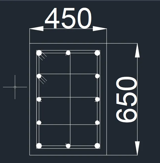
Cross section of column which I have provided the 32mm at first floor and 25mm dia bar throughout the column after 1st floor in 450mm direction
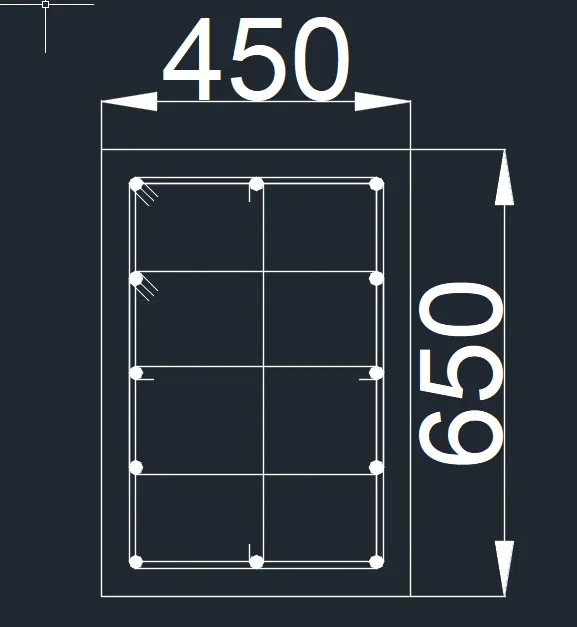
Cross section of column which I have provided the 25mm dia bar throughout the column after 1st floor in 450mm direction
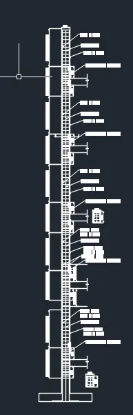
longitudinal section of column which I have provided the 32mm at first floor and 25mm dia bar throughout the column after 1st floor in 450mm direction
Column 450x650mm which I have provided the 32mm and 25mm dia bar at the column in 650mm direction
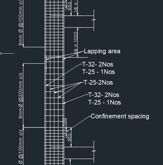
This is the snap shot for 1 floor which I have provided the 32mm and 25mm dia bar the lapping area occured at the column in 650mm direction
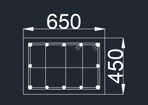
Cross section of column which I have provided the 32mm at first floor and 25mm dia bar throughout the column after 1st floor in 650mm direction
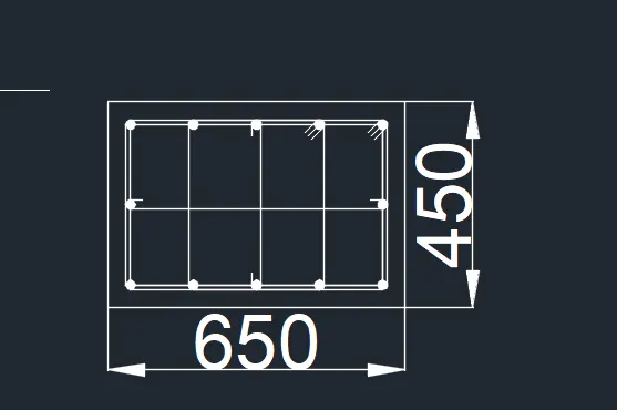
Cross section of column which I have provided the 25mm dia bar throughout the column after 1st floor in 650mm direction

longitudinal section of column which I have provided the 32mm at first floor and 25mm dia bar throughout the column after 1st floor in 650mm direction
So we should take a 100 mm which is a max value
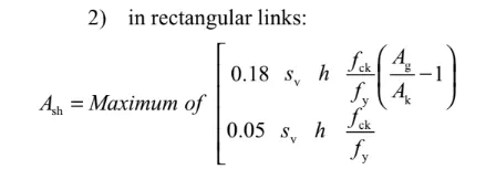
Ash = 720mm^2 (This value is taken from the ETABS)
Result:-
- The ETABS model hass been anaysed after checking the model
- The concerete frame design also carried out
- The longitudianal reinforcement and shear reinforcement details obtained by the ETABS result has been drafted in the AutoCAD
- The Grid along A-3 column and Grid along B-3 column has successfully designed