Conceptual design of a building with columns and shear walls
1.
In this question we have to compare the 3 plans
Here let me name it as Option A, Option B and Option C
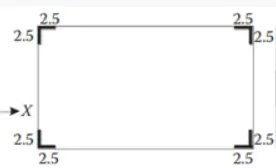
Option A
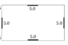
Option B
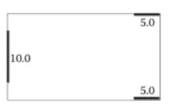
Option C
|
Criteria |
Option A |
Option B |
Option C |
|
|
Restrained of floor shrinkage |
Observation |
Full restrained at all corners |
Corners are left free but restrained along the edges |
Non-uniform restrained |
|
Conclusion |
Option A will have higher restraint to shrinkage, thus leads to crack in floors. Option B is average and Option C will not effectively restrain the shrinkage, so possibly less cracks. |
|||
|
The lateral stiffness |
Observation |
Comparatively lower lateral stiffness in both x and y direction |
Uniform and comparatively higher lateral stiffness in both x and y |
Non-Uniform lateral stiffness in both x and y |
|
Conclusion |
Option B will provide higher lateral stiffness for a pure seismic acceleration in x and y direction |
|||
|
Torsion with respect to vertical axis |
Observation |
Corner walls provides more resistance to twist |
Edge wall provides good resistance to twist |
Irregular walls provide very poor resistance to twist |
|
Conclusion |
Option A will be best option with respect to torsional resistance whereas Option C is the worst one |
|||
|
Vertical reinforcement for similar base capacity |
Observation |
Walls are subjected to nominal flexural moment and heavy twisting moment |
Walls are subjected to nominal twisting moment |
Walls are subjected to heavy flexural moment and twisting moment |
|
Conclusion |
Option C will require higher vertical reinforcement and Option B will require the least |
|||
|
Static eccentricity |
Observation |
Structurally symmetric |
Structurally symmetric |
Un-symmetric |
|
Conclusion |
Only Option C will have static eccentricity and it is significant |
|||
|
System redundancy |
Observation |
Uniform placement of lateral load supports in both the axes |
Uniform placement of lateral load supports in both the axes |
Concentrated lateral load supports in both the axes |
|
Conclusion |
Option A and B are more redundant than the Option C |
|||
|
Foundation system |
Observation |
Due to L shaped walls, the geometry of foundation and its design will be critical |
Walls are in line. Easy to fix the geometry and design of foundation |
Walls are in line and concentrated. Easy to fix the geometry of foundation but critical in design |
|
Conclusion |
Option B and Option C shall be incorporated with isolated footing / strip footings. Option A is recommended to have peripheral box foundation |
|||
|
Architectural constraints |
Observation |
Wall obstruct only corners |
Wall obstruct face of building |
Vertical wall will not allow passage |
|
Conclusion |
Architecturally speaking, Option A is the preferred one. Option B is subjected to discussion. Option c will not be accepted both architecturally and commercially |
|||
2.
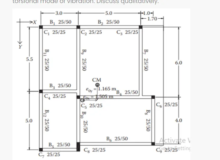
Issues in the given framing plan
Indirect lateral load transfer in x and y direction:- The beams are connected to another beam which is ineffective during lateral load transfer, In such conditions, the primary beam prone to shear failure.
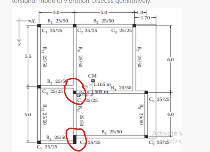
Improper transfer of lateral load in x- direction
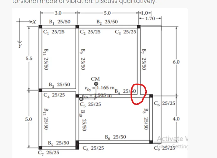
Improper transfer of lateral load in y- direction
Eccintricity:- The longer the distance between the center of mass and center of stiffness, the higher torsional moment of building. As per the given plan eccintricity, the building is subjected to higher torsional moment (Torsional flexibility) in both x nad y directions.
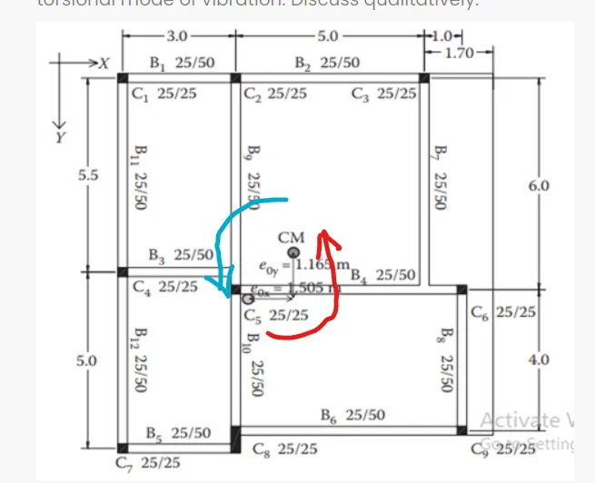
- Here red arrow indicates the torsional innfluence during X - direction excitation
- Here blue arrow indicates the torsional innfluence during Y - direction excitation
Strong beam and week column possibility
The size of the column is majourly mentioned as 25cmx25cm. But all the beam have deeper sections (50cm). Inertia of beam is visually higher than column. If the column reiforcement is adequatly greater than that of beam, we are okay and since we do not have the reinforcement details, this is doubtful. It is recommended to have slight bigger sizes for column
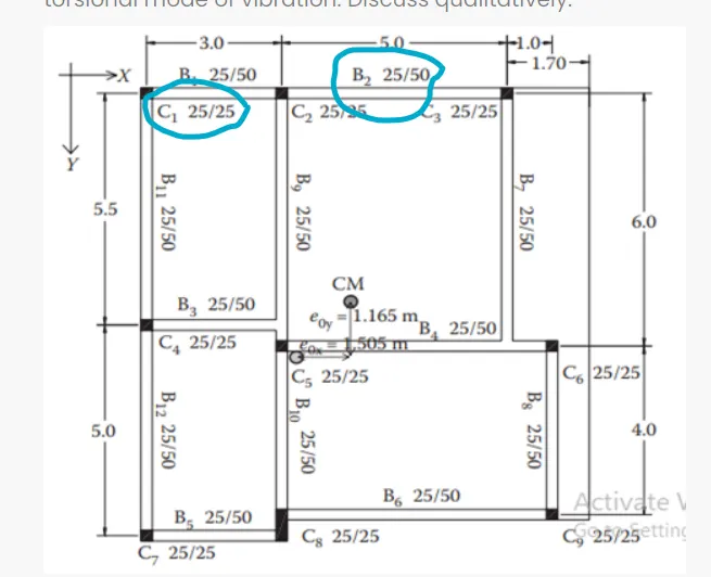
Here the column size is 250x250mm and beam size is 250x500mm this leads to strong beam and weak column
Alternate scheme
- Here all the columns and beams should aligned in straight
- Here beams can be projected from the column to get a chejja / Projected slab
This is the drawing given in the question
- In this question there is a problem in Improper transfer of lateral load, Eccintricity, and Strong beam and week column
- To avoid this problem the column andd beam placement should be in proper manner
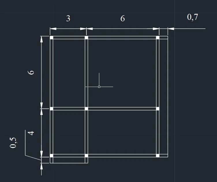
By using this plan all the problems like Improper transfer of lateral load, Eccintricity, and Strong beam and week column can be controlled
3.
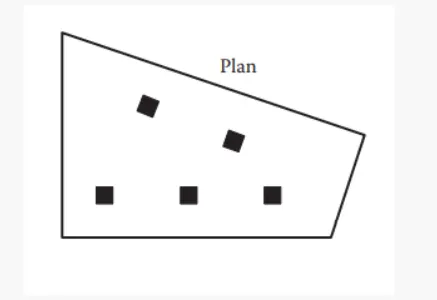
Observation in the given framing plan
Floor Plan :- The floor plan of building is not either uniform or symmetric. So Naturally any lateral load induced in the floor will not have 100% influence in same direction. Definitely a special lateral load resisting system for these torsional moments should be accomodated.
Random internal columns :- Since the internal columns are random, they are unable to transfer the lateral load efficiently and cannot achieve desirable building response. So we have to assume and design those column for only gravity load
Floor to floor variation in partition walls and beams:- Partition walls provides an important mass control in a buildings and beams can play a key role in shear transfer from floor to beam. All these elements are not in order. So heavy distortion and distribution of lateral load will happen.
Suggested on lateral load system and its foundation
- Heavy torsional forces should be controlled by respective lateral load system. So corner shear walls are suggested
- The proportion of floor area is greater on the left side than the left side (irregular quadrilateral). So the corner shear walls on the left side should be heavier than the right
- Corner shear walls preferably supported over a box foundation. Shear walls should be connected by link beams to transfer shear from one to the another
- The internal columns shall be supported by isolated footings. Those isolated footings can be connected with shear wall through tie beam
Proposed schematic plan
- In the super structure the corner shear walls and link beams are provided to withstand the lateral load
- In the sub structure the box foundation are provided to extend the corner RC shear wall, tie beams are used to connect between columns, and isolated footings are provided to place and extend the columns
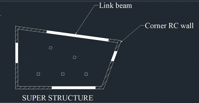
This is the AutoCAD model for super structure
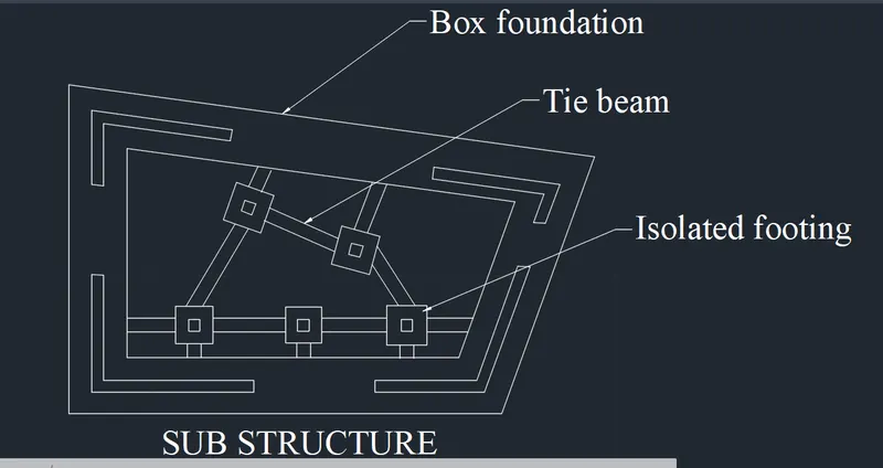
This is the AutoCAD model for sub structure