Creating various 3D Models like Furniture, Footing, Girder, Column drop with panel and Gable Wall in AutoCad
Aim:- To create various 3D models like furnitures, footing, girder, column drop with panel and gable wall by using AutoCAD
Introduction:-
- Furnitures are the important material which is used in building for seating, wardrobe,dining etc.,
- Footing is the importat structure in the building which carry the heavy load from the structure and transfer into the soil
- Girders are the beams which helps to carry load from slab to beams
- Column drops with panels are used to reduces the punching shear of the column
- Gable wall is a section of a wall located at the ends of the pitched roof between the edges of the pitches
AutoCAD:-
It is essential to draft the geometry
The different tools required in this drafts are line (L), fillet (F), offset (O), Hatching (H) and Hatch edit (HE), trim (TR), Extrude (EXT), 3D Move (3DM), 3D Orbit (3DO), 3D Rotate (3DROTATE), Subtract (SUB), Solid edit (SOLIDEDIT), Loft (LOFT), Rectangle (REC), Circle (C), Boundary (BO).
Procedure:-
- Go to start menu, click on Start drawing
- Type stratup (Enter) in command line
- Enter the new value of start up:1
- Go to application menu and select new or type new in command line
- In the "create new drawing" dialogue box contains imperial type of systems and metric type of system
- We select the metric system in the "start from scratch" option
- After that in Advance setup option select the decimal unit system in the units
The above procedure should be followed every time when the new sheet is opened
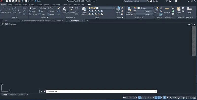
Entering the start up command in the command line
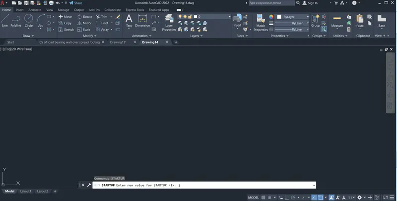
Entering the value 1 for the start up
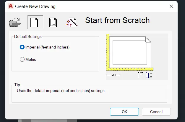
When we go to the new file then we get this file select the metric from start from scratch
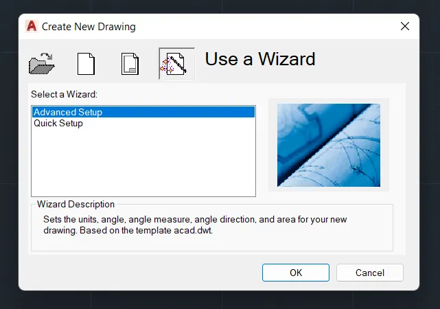
Then advance setup setting should be done by clicking OK
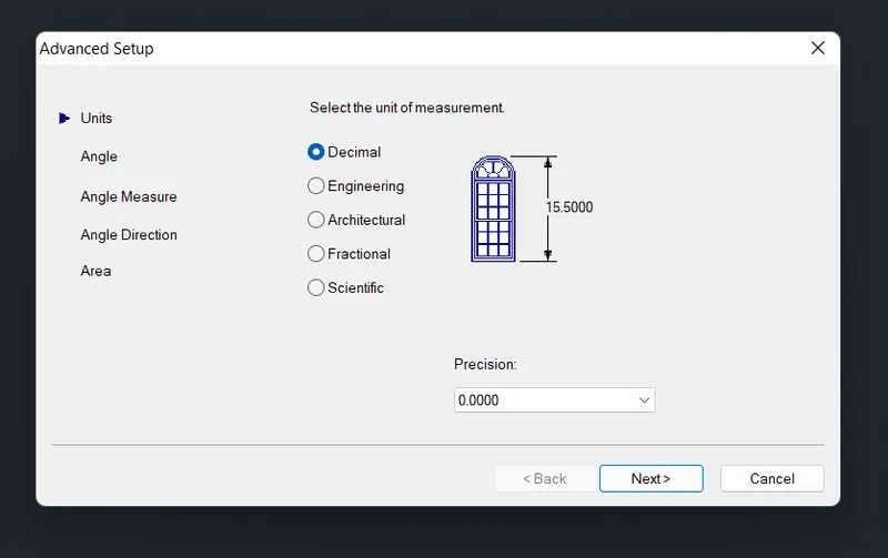
Keep the units in decimal and adjust precision then click next
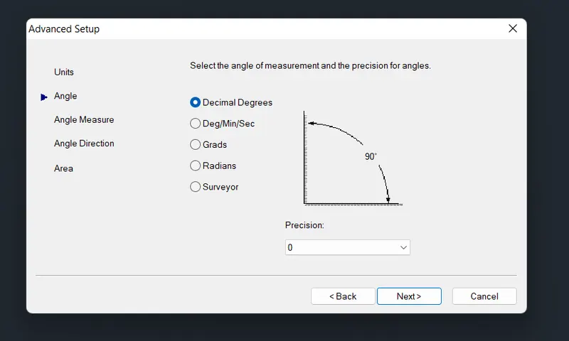
Keep angle in decimal degree and adjust precision then click next
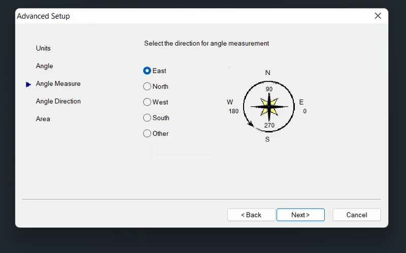
Select the angle measurement in east and click on next
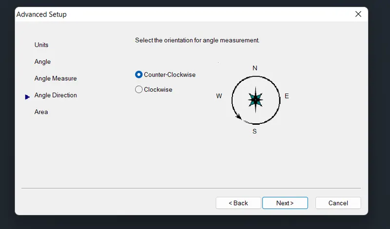
Select angle direction in counter clockwise and click on next
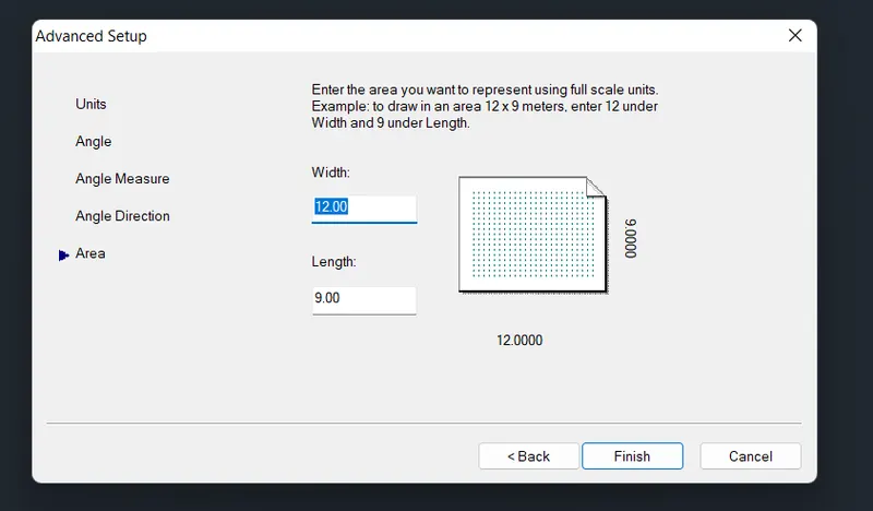
Keep the width as 12m and length of 9m as default and click on finish
Aim:- To draft the 3D model Furniture by using AutoCAD 3D
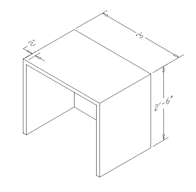
Procedure:-
By using direct distance entry method
- Here all the units are in Imperial (feets and inches)
- Go to 2D wire frame keep the view at top
- Draw a rectangle having a dimension 3'x3' by using a rectangle command (REC)
- Take a offset of 2" inside the rectangle by using a command (O)
- Go to south west isometric view
- Take a extrusion heigth of 2'-6" by using a command EXT
- Then use a substract command to deduct the inner rectangle 2'-10"x2'-10" (2" offseted rectangle) from the 3'x3' rectangle
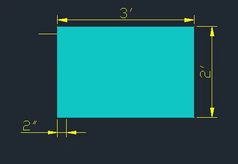
Top view of furniture
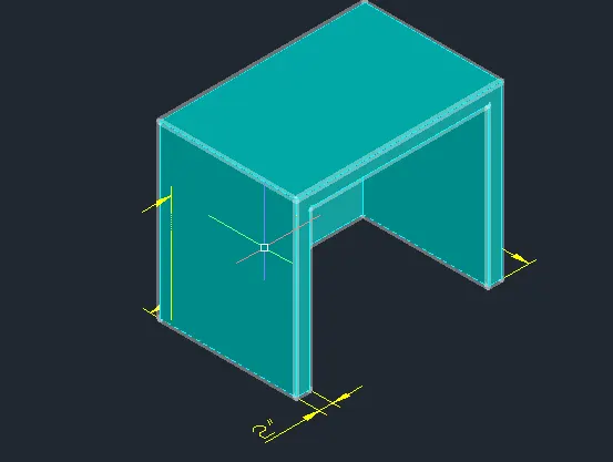
Side view of furniture
Layers used for this model is
- Furniture - Cyan
Result:-
Top view of furniture
Side view of furniture
Aim:- To draft the 3D model isolated footing by using AutoCAD 3D
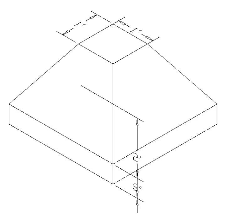
Procedure:-
By using direct distance entry method
- Here all the units are in Imperial (feets and inches)
- Go to 2D wire frame keep the view at top
- Draw a rectangle having a dimension 3'x3' by using a rectangle command (REC)
- Draw a same rectangle having a dimension 3'x3' by using a rectangle command (REC)
- Use a 3D Move command to move the 3'x3' rectangle to a height of 6"
- Draw another rectangle having a dimension 1'x1' by using a rectangle command (REC)
- Use a 3D Move command to move the 1'x1' rectangle to a height of 2'
- Go to south west isometric view
- Use a loft command (LOF)
- Select the cross section in lofting order (The cross section should be atleast 2)
- Select 3'x3' rectangle having height of 6" and 1'x1' rectangle having height of 2'
- Then select the base face of the 3'x3' rectangle which is loft then extrude it to 6" downwards
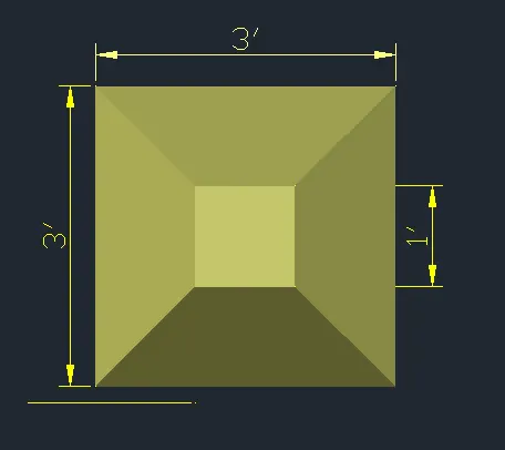
Top view of isolated footing
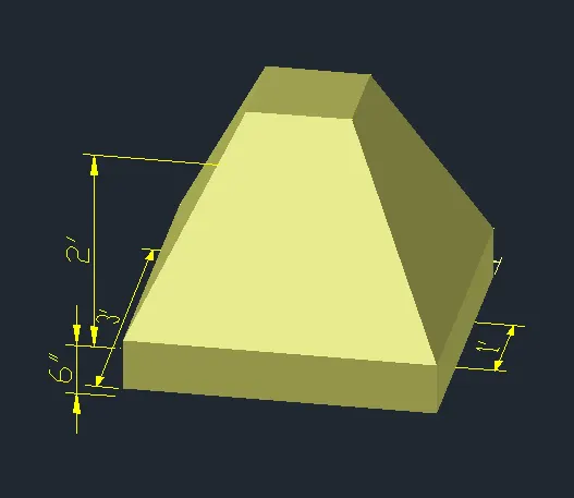
Side view of isolated footing
Layers used for this model is
- Isolated footing - ACI 51
Result:-
Top view of isolated footing
Side view of isolated footing
Aim:- To draft the 3D model Girder by using AutoCAD 3D
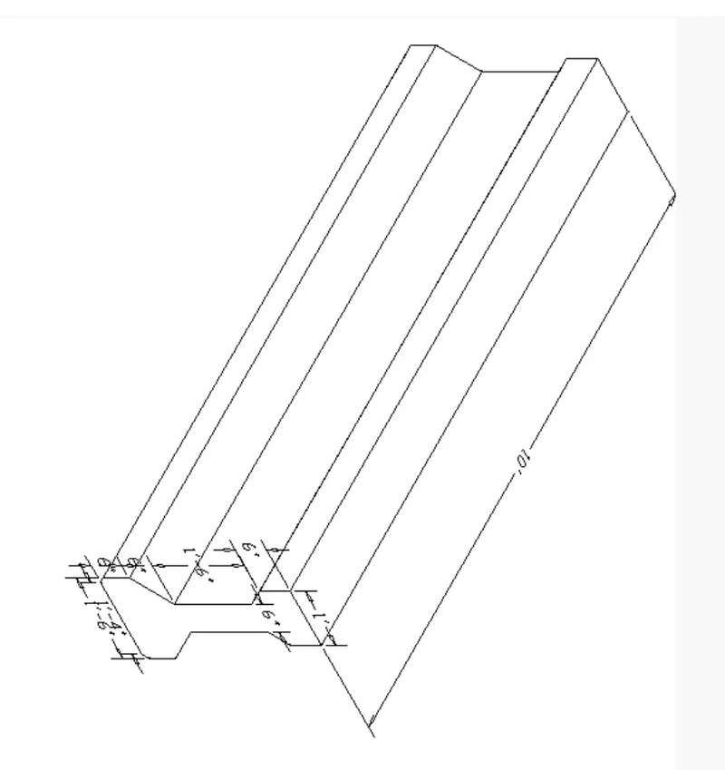
Procedure:-
By using direct distance entry method
- Here all the units are in Imperial (feets and inches)
- Go to 2D wire frame keep the view at top
- Draw a line having a length 1' by using a line command (L)
- Draw a line having a length 6" by using a line command (L) at the both the ends
- Draw a line randomly from the mid point of the 1' line then take a offset of 3" either sides left and right
- Connect the vertically drawn 6" line to the offseted 6" line both in left and right side
- Trim off the remaining things by using a command TR
- Take a line having a length 1'-6" from the 6" vertical line both the sides
- Draw a line randomly from the mid point of the 1' line then take a offset of 9" either sides left and right at the base then the distance should be 1'-6"
- Draw a line having a length 6" by using a line command (L) at the both the ends upwards
- Then connect the lines in inclination both in left and right side
- Use a 3D Rotate command to rotate the model in x- direction
- Take a offset having a radius 1" then select the edges of the 1'-6" line at the both ends then the inner distance will become 1'-4"
- Go to south west isometric view
- Then extrusion at a length of 10'-0" by using a command EXT
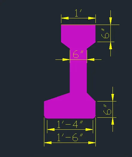
Top view of Girder
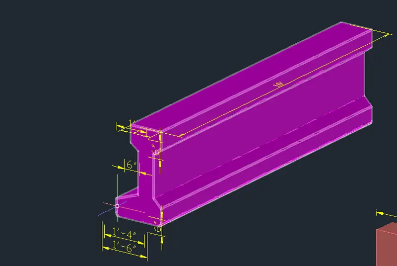
Side view of Girder
Layers used for this model is
- Girder - Magenta
Result:-
Top view of Girder
Side view of Girder
Aim:- To draft the 3D model of a drop column with panel by using AutoCAD 3D
For Rectangular column
Procedure:-
By using direct distance entry method
- Here all the units are in Imperial (feets and inches)
- Go to 2D wire frame keep the view at top
- Draw a rectangle having a dimension 10'x1'-6" by using a rectangle command (REC)
- Draw a line having a length 3'-6" from the right side of 10'x1'-6" rectangle at a distance of 1'
- Then connect ends of the 3'-6" line to the rectangle having an inclination 45 degree
- Draw a rectangle having a dimension 6"x4'-6" by using a rectangle command (REC)
- Then connect this rectangle to the mid of the 3'-6" line
- Go to south west isometric view
- Then use extrusion command to extrude the column (10'x1'-6" rectangle) at 9"
- Then use extrusion command to extrude the drop and panel (3'-6" line and 6"x4'-6"rectangle) at 2' at left and 2' at right
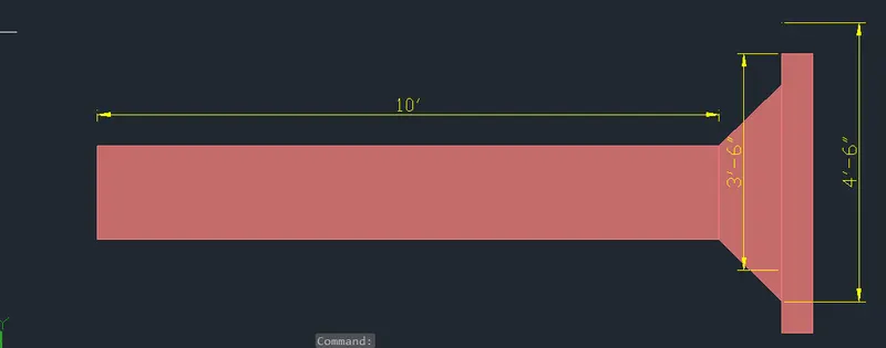
Front view of Rectangular column
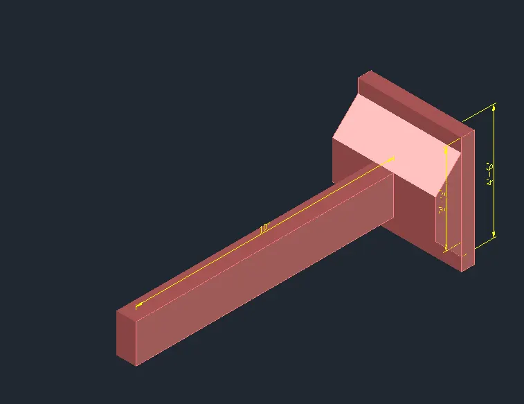
Side view of rctangular column
For Circular column
Procedure:-
By using direct distance entry method
- Here all the units are in Imperial (feets and inches)
- Go to 2D wire frame keep the view at top
- Draw a circle having a dimension 1'-6" dia by using a circle command (C)
- Draw a line having a length 3'-6" from the right side of 1'-6" dia circle at a distance of 1'
- Then connect ends of the 3'-6" line to the rectangle having an inclination 45 degree
- Draw a rectangle having a dimension 6"x4'-6" by using a rectangle command (REC)
- Then connect this rectangle to the mid of the 3'-6" line
- Go to south west isometric view
- Then use extrusion command to extrude the column (1'-6" dia circle) at 9"
- Then use extrusion command to extrude the drop and panel (3'-6" line and 6"x4'-6"rectangle) at 2' at left and 2' at right
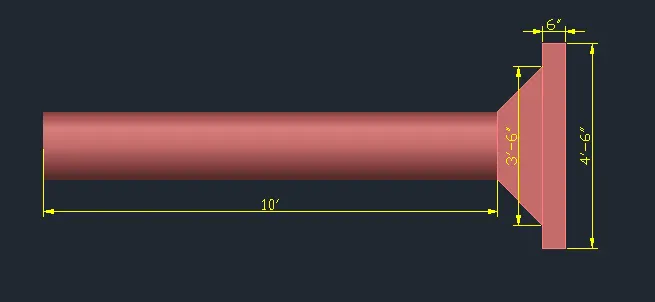
Front view of circular column
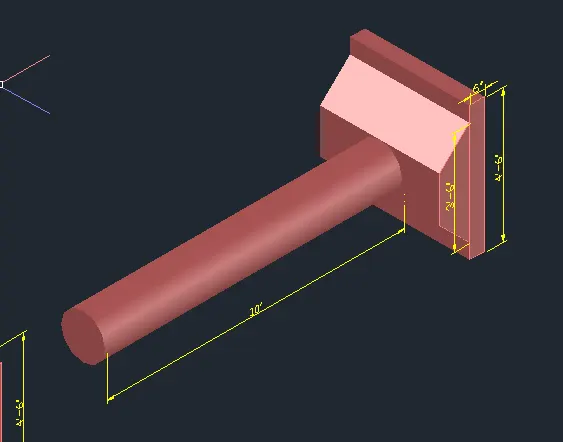
Side view of circular column
Layers used for this model is
- Column drop with panel - ACI 11
Result:-
Side view of rctangular column
Side view of circular column
Aim:- To draft the 3D model of Gable wall by using a AutoCAD 3D
Procedure:-
By using direct distance entry method
- Here all the units are in Imperial (feets and inches)
- Go to 2D wire frame keep the view at top
- Draw a rectangle having a dimension 10'x12'-6" by using a rectangle command (REC)
- Draw another rectangle having a dimension 3'x7' by using a rectangle command (REC)
- Take a Move command (M) then select a rectangle having a dimension 3'x7' specify the base point as a bottom line mid and place it in the mid of the 10'x12'6" rectangle
- Take a 3D chamfer command and chamfer the left edge by taking a 2'-6" as a first chamfer distance and 5' as a second chamfer distance
- Take a 3D chamfer command and chamfer the right edge by taking a 5' as a first chamfer distance and 2'-6" as a second chamfer distance
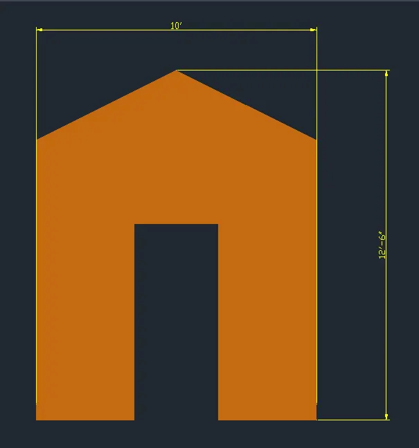
Front view of Gable wall
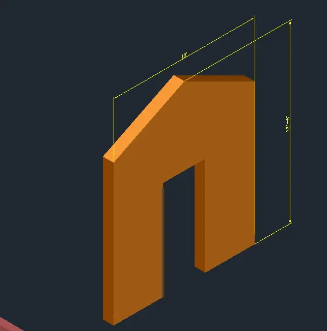
Side view of Gable wall
Layers used for this model is
- Gable wall - ACI 30
- Dimension - Yellow
Result:-
Front view of Gable wall
Side view of Gable wall
Layers for drawings are
- Furniture - Cyan
- Isolated footing - ACI 51
- I section Girder - Magenta
- Column drop with panel - ACI 11
- Gable wall - ACI 30
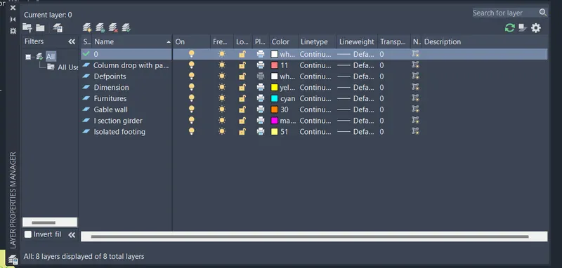
The drawing file for all these drawings are mentioned below