Creating Architectural and Structural model with 3D rendering using REVIT
1.
Aim:- Select the type of structure you want to build from one of the three below:
a. Multi-Unit Residential Apartment
b. Office Buildings
c. School
a. Multi-Unit Residential Apartment
2)
Aim:- Assume reasonable assumptions for geographic and location details for your project modeling. Based on assumptions and type of structure selected identify the modeling requirements from NBC
- The model is a Multi-Unit Residential Apartment
- This model is in a plain area
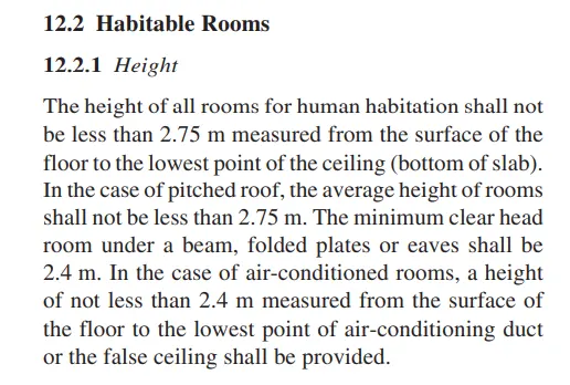
- According to NBC the height of the building should not less than 2.75m but In this project the height of the building is 3m
- The plot size is 2500sqm = 2500sqm
- The floor size is 678.78 sqm = 680sqm
- No of floors = 5
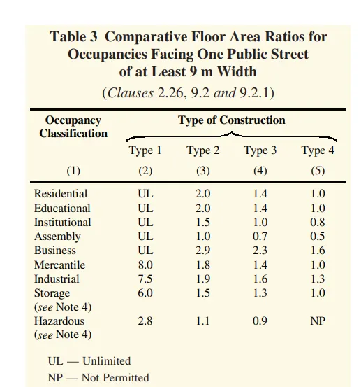
Floor area ratio = Total area of building/Plot size
= 680*5/2500
= 1.36 = 1.4 sqm
- So this model comes under type 3 construction
3)
Aim:- Using the structural model, include the following components based on the type of structure selected
a. Foundation – Isolated / Wall/Matt Foundation
b. Columns
c. Beams Connected to Columns
d. Roof Framing/ Truss
e. Floor / Decks
f. Floor Openings for Elevators and Stairs
Introduction:- Structural model is a model that contains a structural components like beam, column, floor, roof, footing
- Structural components carry heavy load and transfer it into the foundation
Procedure:-
Step1:-
- Before starting the structural model
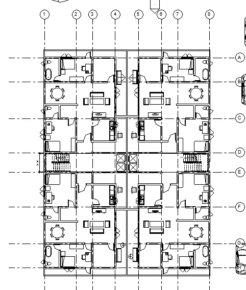
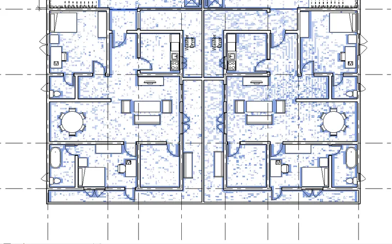
- Create a plan in Architectural template along with grid lines
- This plan is about the Multi-Unit Residential Apartment
- Architectural model looks like as shown below
Step2:-
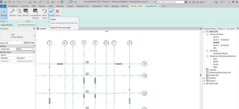
- After creating the architectural model then open the structural template project file
- Then make it as a central model
- After that by using a manage link, link the architectural model into it
- Then by using a copy monitor copy the grid lines
Step3:-
- After copied the grid lines then take a copy clipboard option then past the grid lines to the different levels
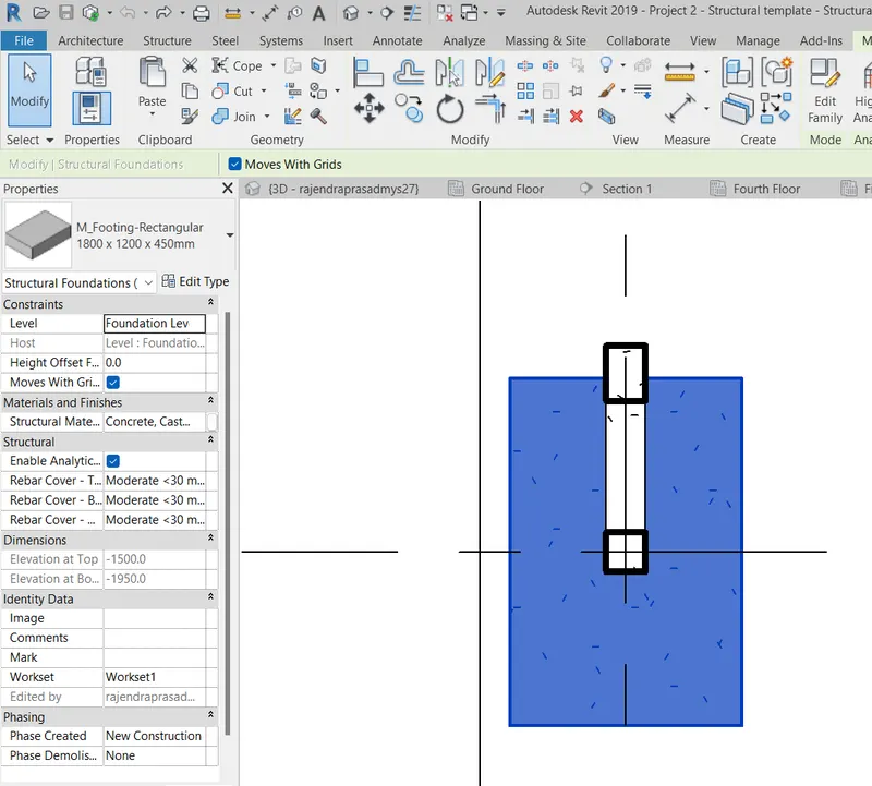
- Then place a isolated footing from the structure tab in the foundation level
- The dimension of the footing is 1800x1200x450mm
Step4:-
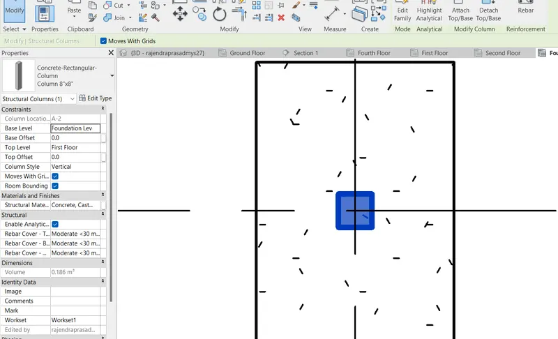
- Then place a column from the structure tab in the foundation level then change the levels to the roof level
- The dimension of the column is 8"x8"
Step5:-
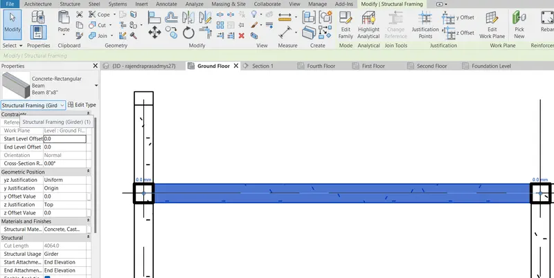
- Then place a beam from the structure tab in the ground floor level then take a copy clipboard option then past the beams to the different levels
- The dimension of the beam is 8"x8"
Step6:-
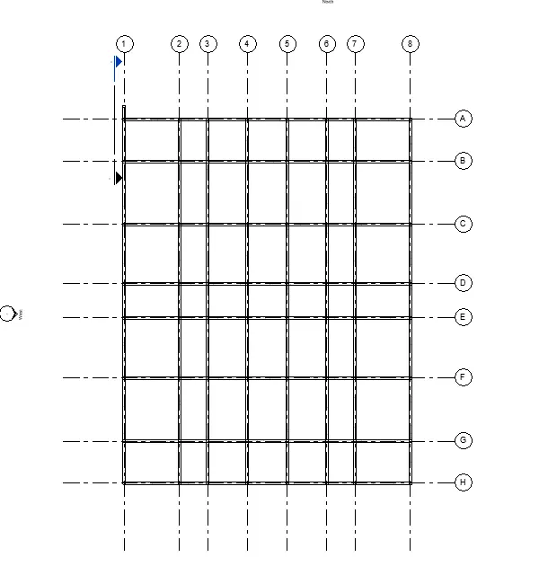
- The dimension of the beam is 8"x8"
- The beam placement is as shown below using the grid lines
Step7:-
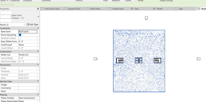
- The dimension of the roof is 12"
- The roof is placed at the top
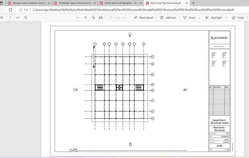
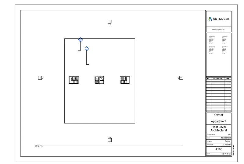
- The roof level is as shown below which contains a stairs and the lift at the top
Step8:-
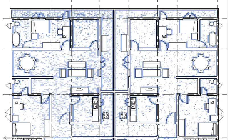
- Floor is a very essential component which divides the levels
- In this snap shot the floor for 1st and 2nd unit is shown
- One floor is provided throughout the unit
Step9:-
- In this snap shot the floor for passage in unit is shown
- One floor is provided throughout the unit

Step10:-
- Floor is a very essential component which divides the levels
- In this snap shot the floor for 3rd and 4th unit is shown
- One floor is provided throughout the unit
Step11:-
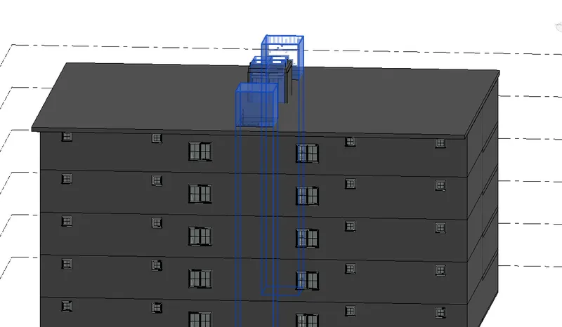
- Floor opening is used to provide the lift and staircase
- In this snap shot the opening is given by using a shaft opening
- This opening is provided from ground floor to the roof
Step12:-
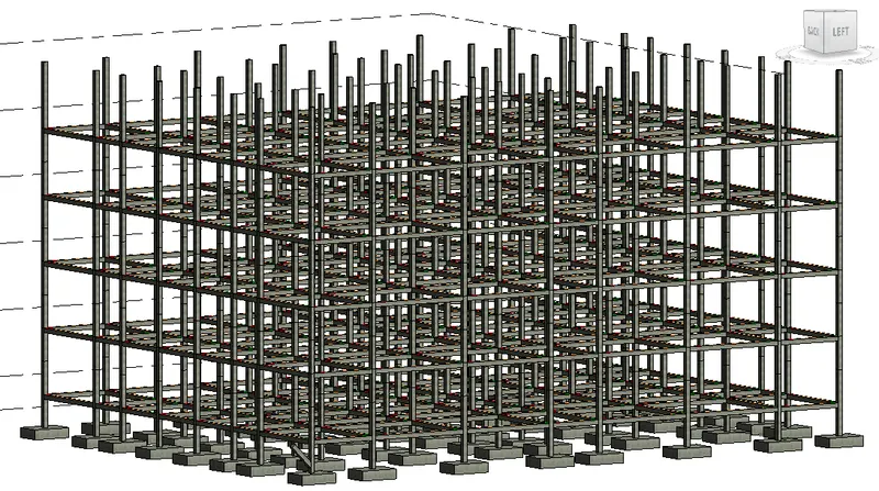
- This is the 3D model of the structural model
- It contains the columns, footings, beams
Result:-
This is the 3D model of the Architectural model
This is the3D model of the structural model
4.
Aim:- Using the architectural model, include the following components based on the type of structure selected
a. Wall Layout with appropriate material and finishing
b. Exterior façade with fancy finish
c. Interior partition walls to size rooms
d. Components to add details to a room ( Desk, Chair, Lighting, Plumbing fixtures)
e. Add components such as stairs Elevators
f. Have at-least one side of the building with curtain walls and glass panels
g. Include interior and exterior lighting fixtures
h. Place proper topographic components from outside ( Trees, Parking, Plants) to add details to the model
Procedure:-
Step1:-
- Open a architectural model which you have saved
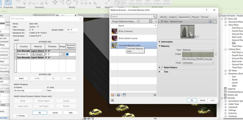
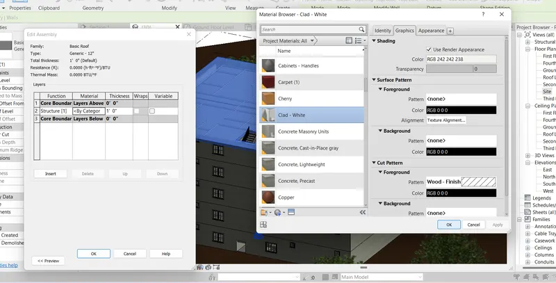
- To provide the materials to the wall go to the edit type then click on the by category then select the material which you want
- In this project the material for the wall provided is concrete masonry unit
Step2:-
- To provide the materials to the roof go to the edit type then click on the by category then select the material which you want
- In this project the material for the roof provided is clade white
Step3:-
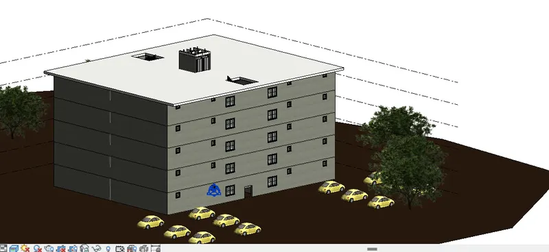
- This is the 3D view of the model
- It contains,
- wall layout the material used for the wall is concrete masonry unnit
- The exterior facade with fancy finishing
- Here only one size of wall is used throughout the building, the size is 8" and for the outsidde balcony region 5" wall is provided
Step4:-
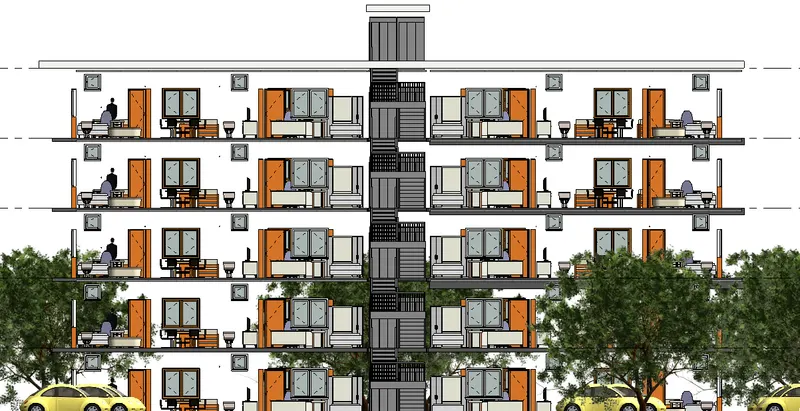
- Here all the nesessary componenets are added to the model
- It consists of a furnitures, plumbing fixtures, entourages, lifts etc.,
Step5:-
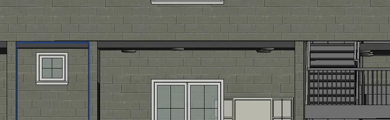
- In this snap shot the ceiling lights are provided to all the room except the bathroom
- For the bathroom the white light is provided
Step6:-
- All the required topographic components are placed here
- The toposurface, trees and car-parking is provided here
Result:-
This building contains all the required elements to the question
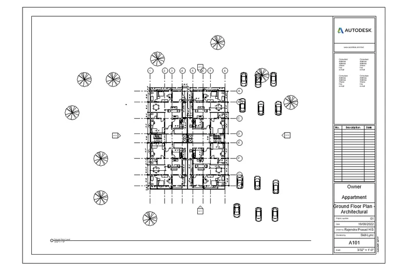
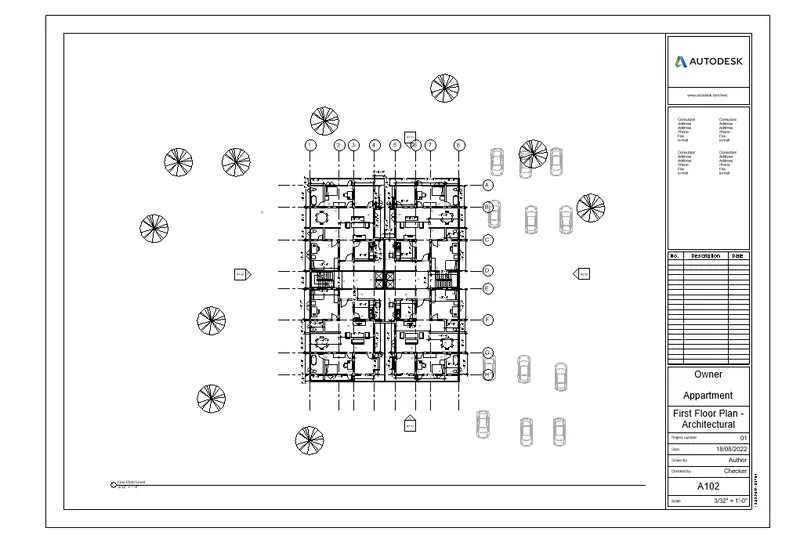
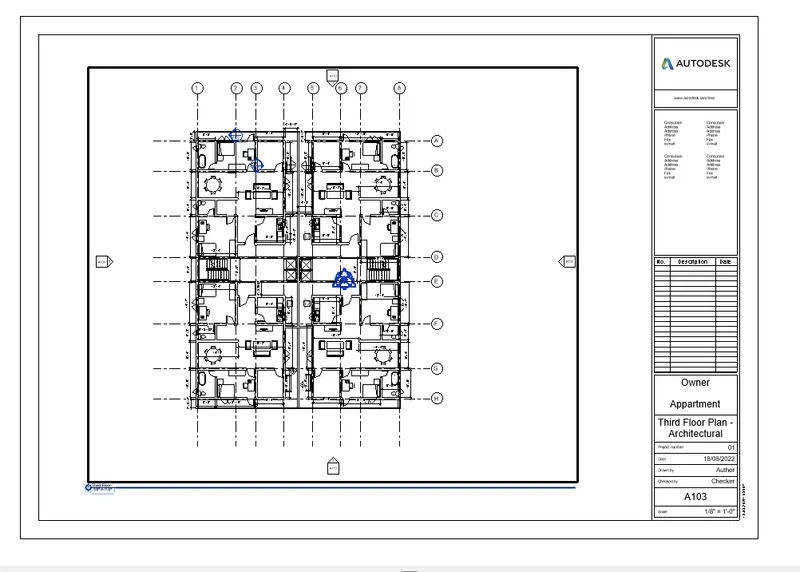
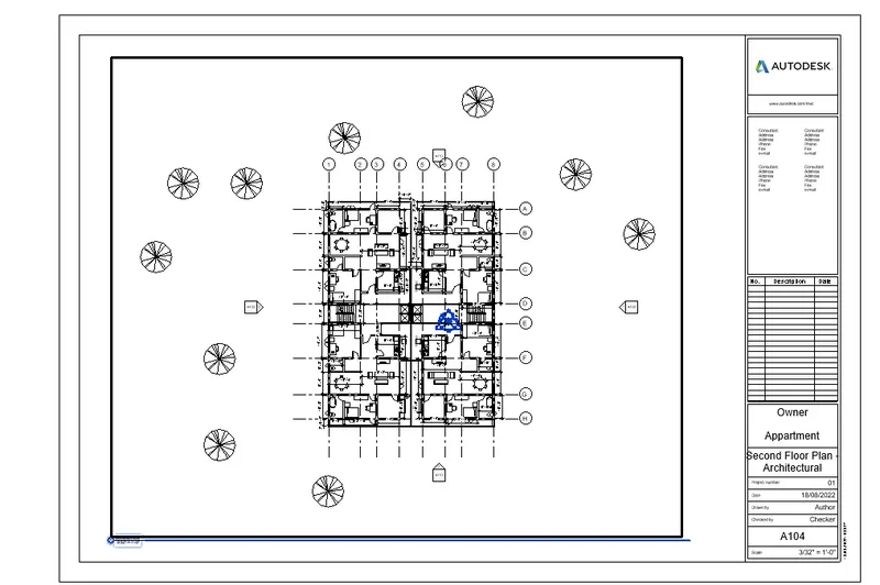
5.
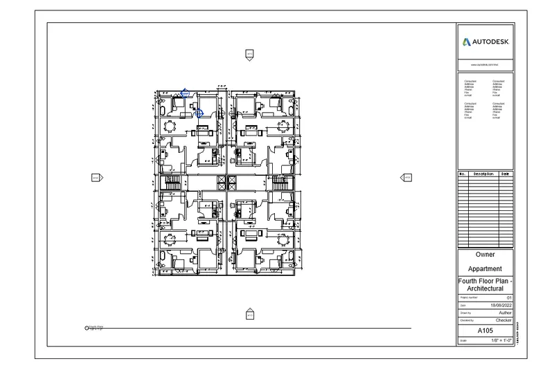
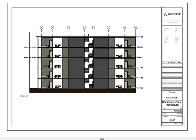
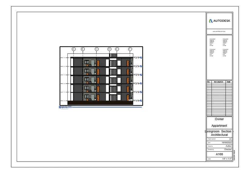
Aim:- Provide a set of drawings in an architectural and structural model to list the following details with categories and appropriate sheet templates included
a. Floor Plans with Annotations
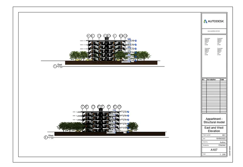
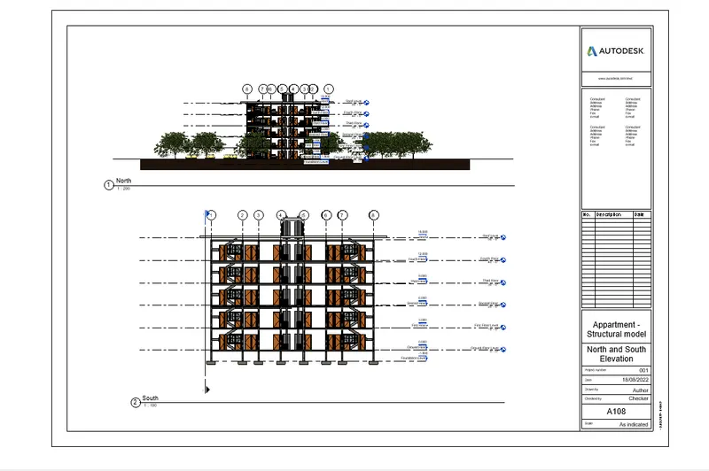
b. Elevations
c. Sections
Sheets :-
- Sheets are used to set the page to place the drawings or images in that sheet
- The drawing/sheet informations should be changed while creating the sheets
Procedure:-
Step1:-
- Open the week 3 project file
- Then go to the sheet which is in the view tab
- Then the new sheet dialouge box opens
- To select the different sheet setup
- Go to the load family then go to the title block and select the A1 metric
- Click on open
- Then select the A1 metric click on OK
- After opening the A1 metric sheet
- Then the default sheet opens
- This sheet is loaded by Autodesk Revit
- After opening a new sheet
- Click on the any floor which you want then that floor appears on the screen
- After opening the default sheet which is A1 metric
- Drag the plan of Architectural plan and Structural plan in to the sheet
- Then change the information in the sheet
Floor Plans of Architectural
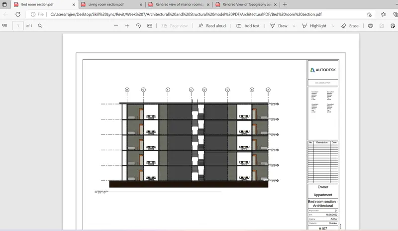
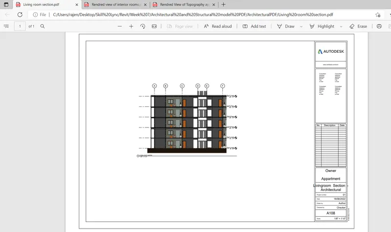
Sections of Architectural
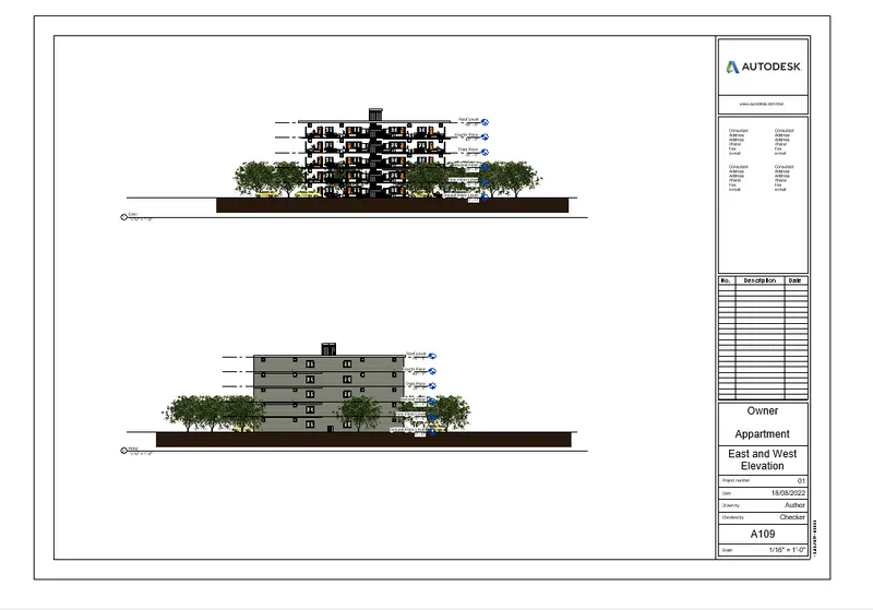
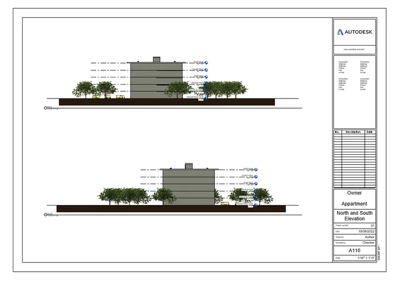
Elevations of Architectural
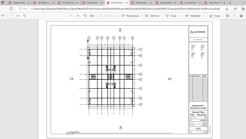
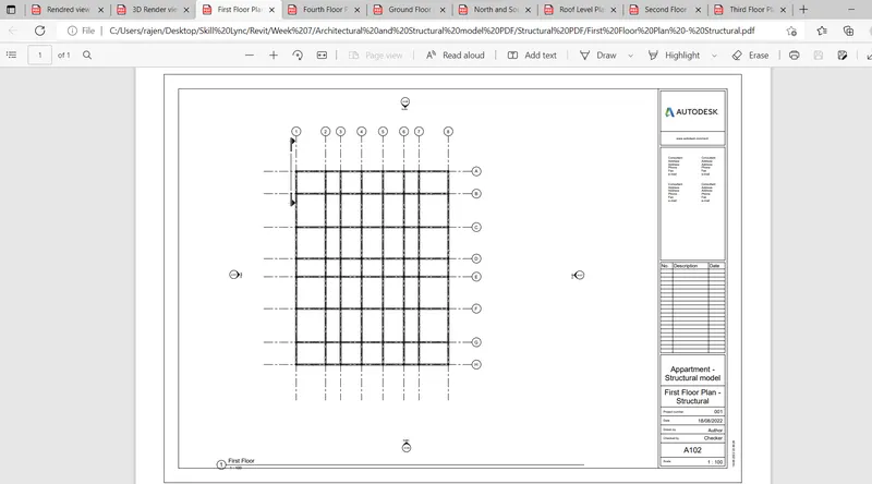
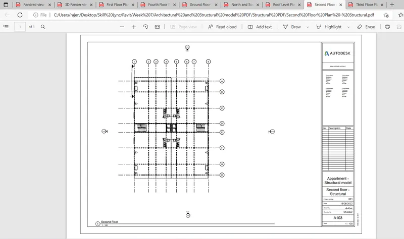
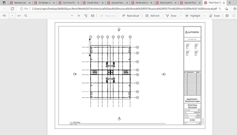
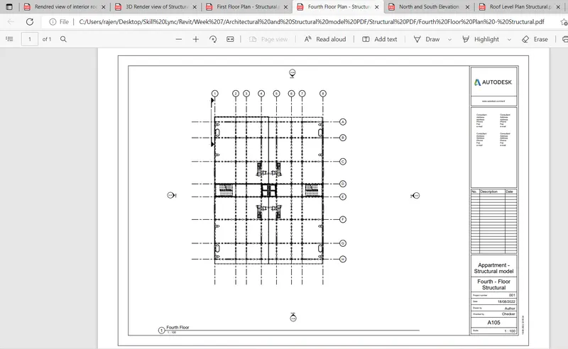
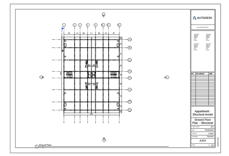
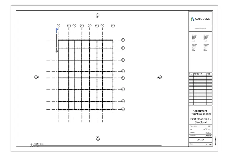
Floor Plans of Structural
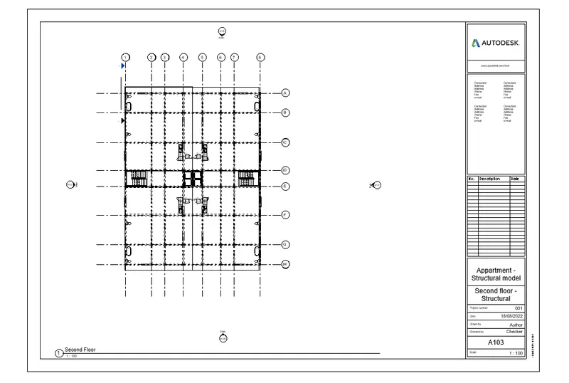
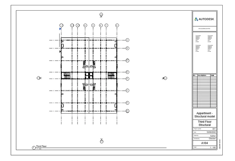
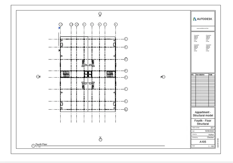
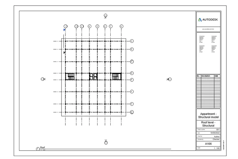
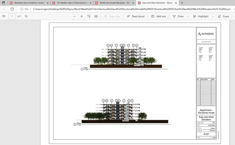
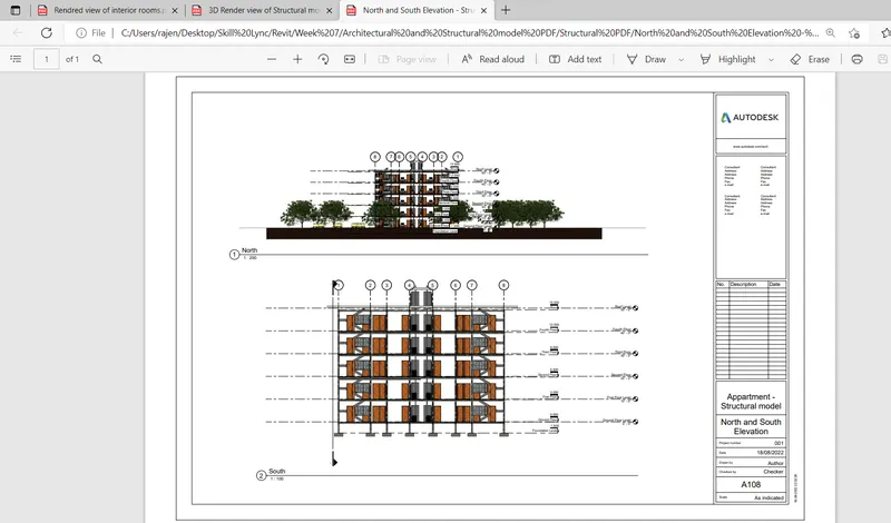
Elevation of Structural
Result:-
All the floor plan, Elevation and section of Architetural model is created and also Plan, Elevation of structural is created
6.
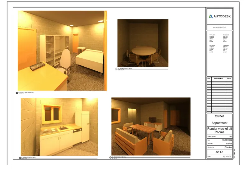
Aim:- Using the Rendering settings, Render images of the 3D model produced and include the rendered images to the drawing sheets
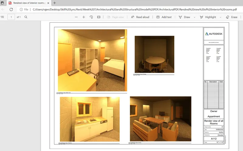
a. Rendering from interior rooms
b. Rendering from out showing topographic features
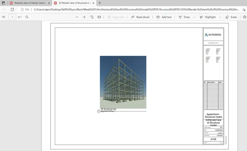
c. Rendering through structural framing
Introduction:- Rendring is a process of getting 3D visualisation from the camera
Rendring settings
- Place a camera near the structural frame by using a view tab
- Then go to the 3D view of the structure in strutural model
- After that make a rendring by using a Render option which is in view tab or type RR this is a short cut key used for rendring
- Then set all the setting in that which is shown below
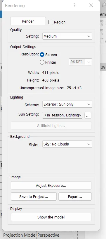
- After Rendring to save the image then click on save to project then give a name for the view
- The saved rendered image is visible at the project browser
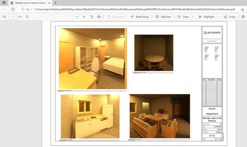
a. Rendering from interior rooms
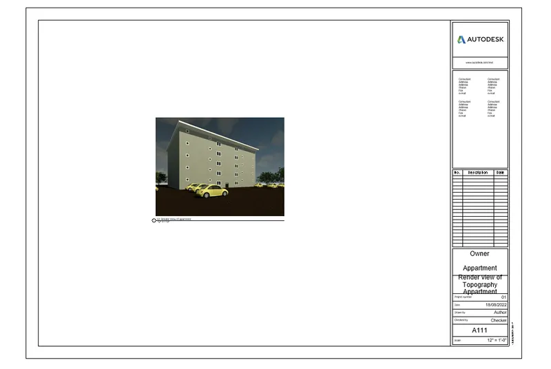
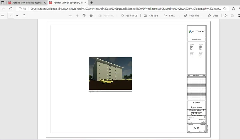
b. Rendering from out showing topographic features
c. Rendering through structural framing
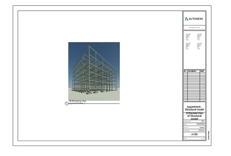
Rendring of structural frame
Result:-
Rendring of interior rooms
Rendring of topography of appartment
Rendring of structural frame
7) Print the set of drawing sheets created and submit the drawings from the architecture and structure model
Introduction:-
Printing:- It is a process of reproducing text and images into the sheet (hard copy)
Procedure:-
Step1:-
- Go to the sheet which you have saved in the model
- To take the print press control+P
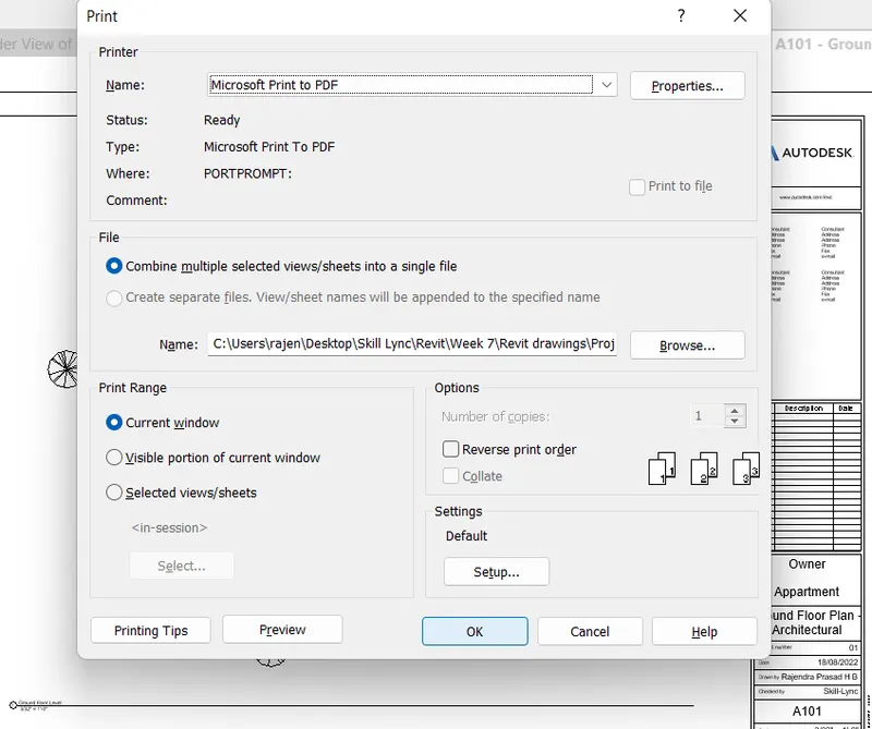
- Then this dialouge bix will opens
- If you want to see the preview of that image click on the preview button
- If you want to take print click on print
Step2:-
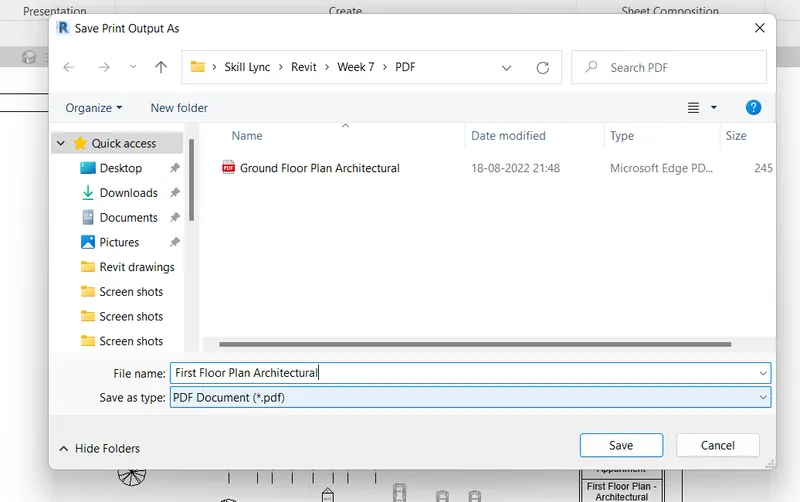
- After clicking the print then save the pdf file where you want
- Select the folder and click on save
Result:-
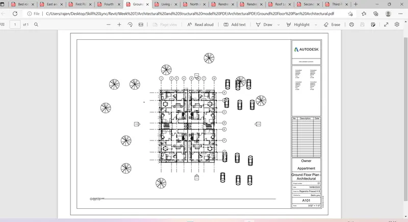
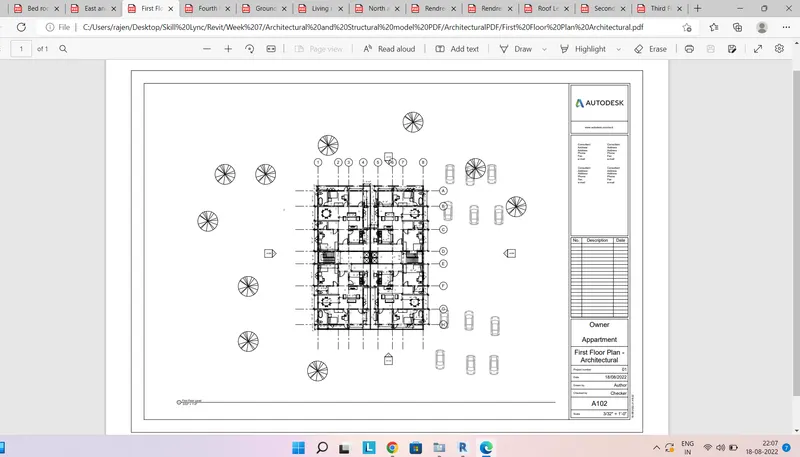
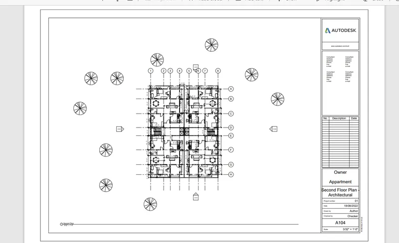
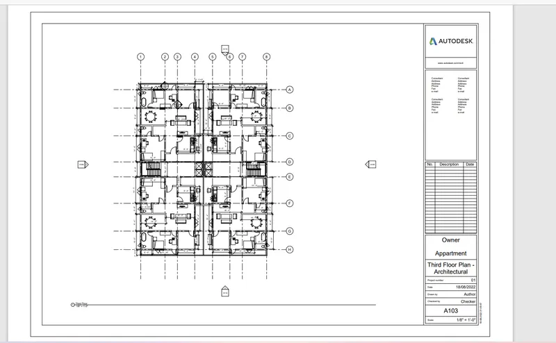
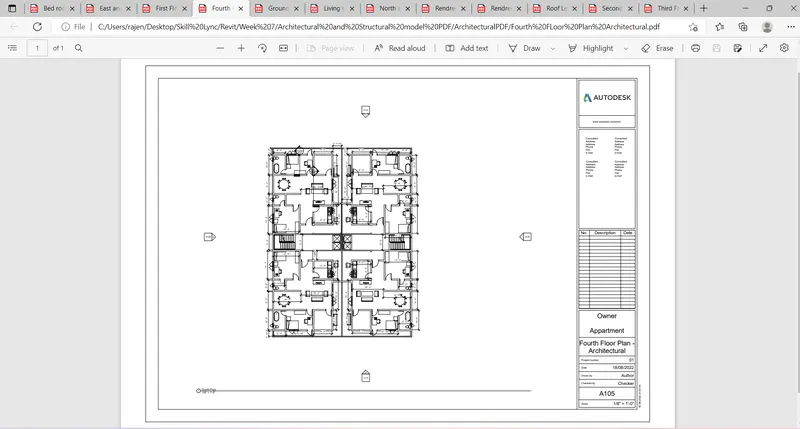
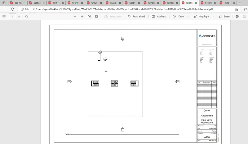
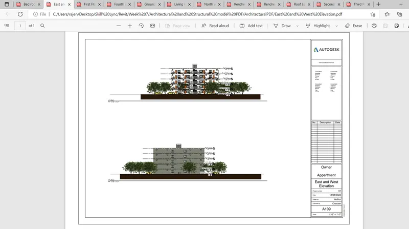
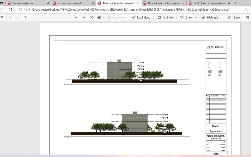
All the sheet setup pages are takend print- It is a Architectural model
All the sheet setup pages are takend print- It is a Structural model