Introduction to REVIT concepts
Aim:- To draft the geometries, to create the new project and to write/change/edit the project by using Revit
Introduction:-
- Revit is one of the important software which gives the 3D view of a biulding in realistic
- Revit software is used by different designators like Architects, Structural engineer, Plumbing department, Mechanical engineer.
- Revit software develops day by day in the world
- Revit also helps us to create the elevation, section, MEP works, schedules, legends etc.,
Procedure :-
- When the Revit software opens then click on the new to create a new project file
- Select any template which requires you
- Select a project or project template which required
- Then click on OK
- The Project 1 file is ready to draft
Aim:- From file menu create a new project (Structural/Architectural/Construction template) and name it appropriately
Procedure:-
Step 1:-
- Open the Revit software by double clicking on that application
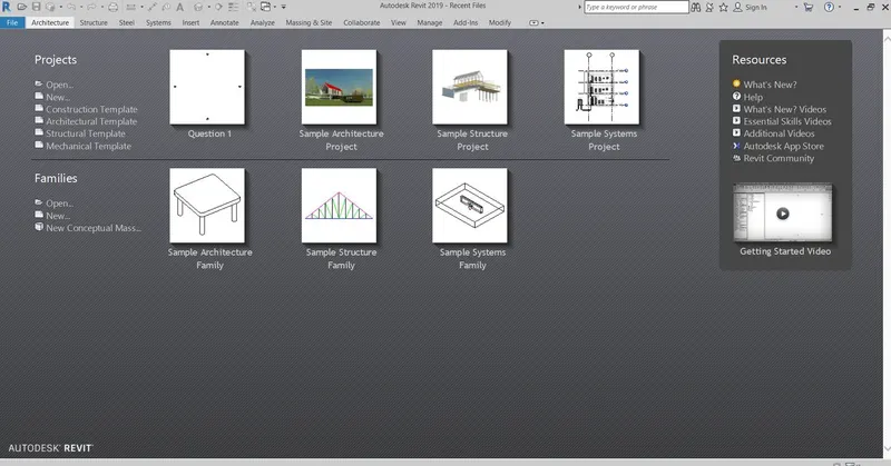
Step 2:-
- Click on the file menu then you will get new tab then click on the new option
- From using new option go to project to create a new project file
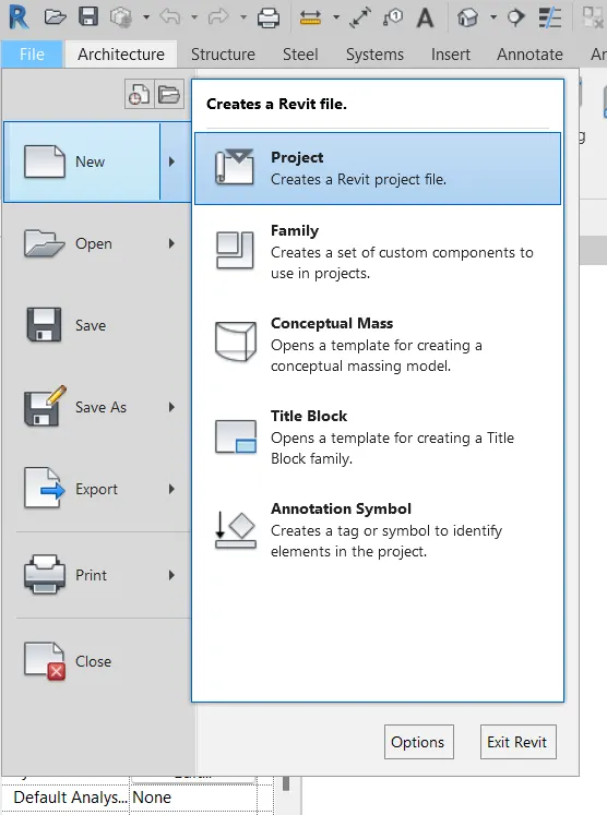
Step 3:-
- When we select the project option then template project dialouge box opens
- Select the Architectural template in the template file then click on the project and click on OK
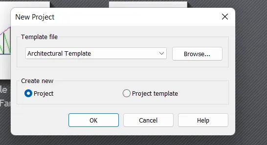
Step 4:-
- After selecting the tempaltes file then your drawing file is ready to draft the geometry
- The default name of the file is Project1 - Floor plan
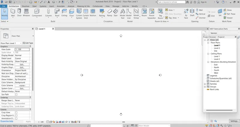
Step 5:-
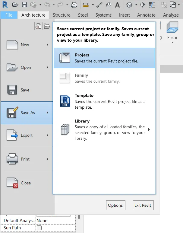
- Next save the file by using a save as option
- Go to the file menu click on save as option then you will get a option like this
- Select project in save as, as shown below
Step 6:-
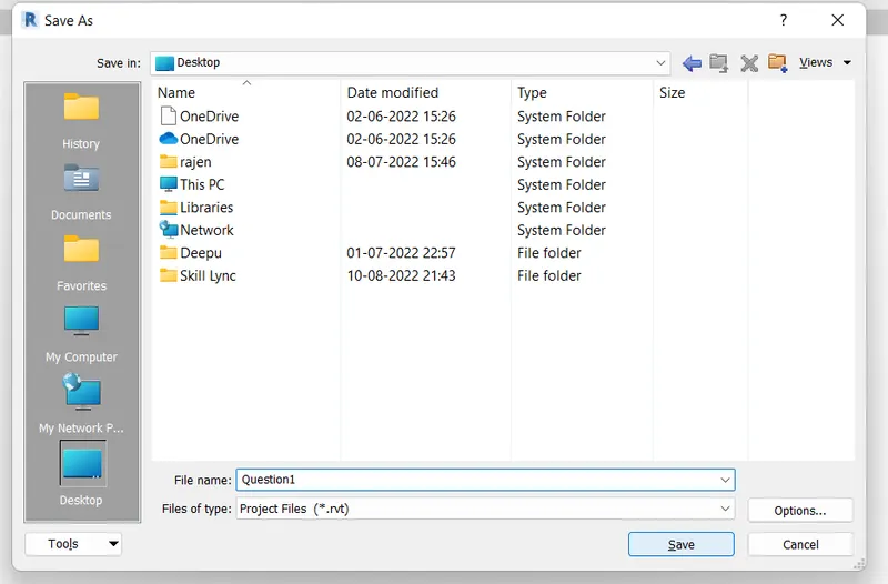
- After clicking on project in save as then this dialouge box will open
- Select the destination of the file and change the file name as your wish
- Then click on save
Result:-

Aim:- To save the new project file close and open using icon from the file tool bar
Procedure:-
Step 1:-
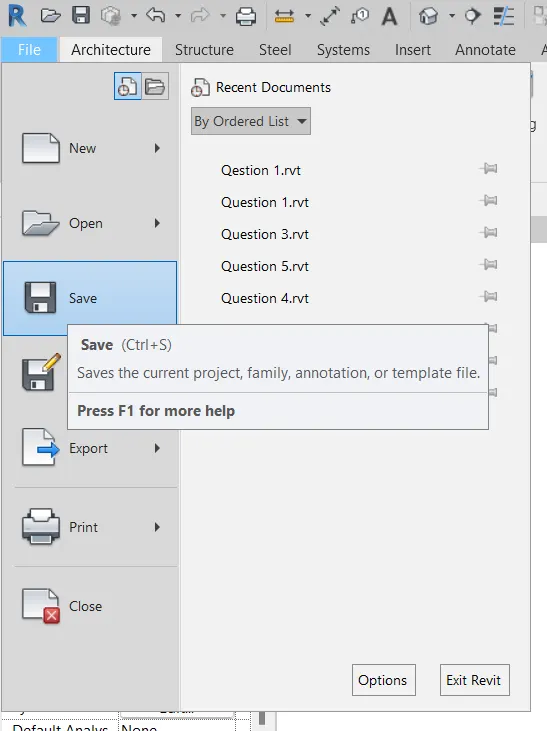
- Go to file menu and click on save option to save the file by giving a different name as your wish
Step 2:-
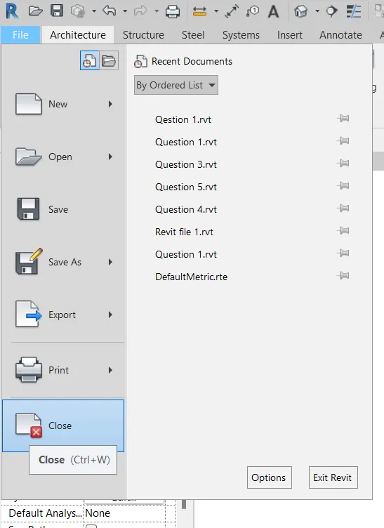
- Here we need to close the project file
- First click on the file menu then click on the close at that time the opened file will close
Step3:-
- When we close the file then we will get like this inn the screen
- Next click on the file which you have closed now then the file will open
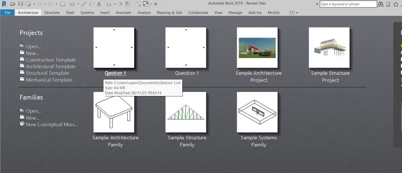
Result:-
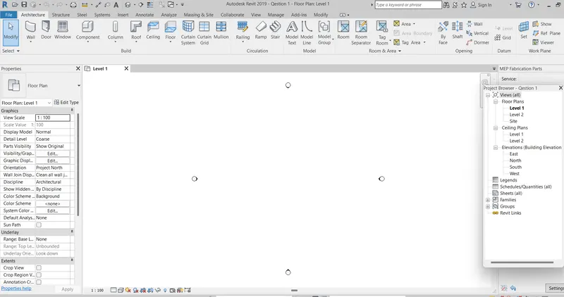
At last we will see this file when we open the file in the recent screen
Aim:- From Architectural/Structure tool bar familiarize with option to draw wall. Create a rectangular layout of a wall of about 40'-0"x35'-0"
Procedure:-
Step 1:-
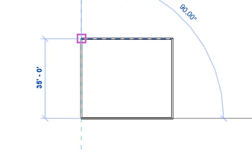
- Draw a rectangular having a dimension 40'-0"x35'-0" layout by using a line option
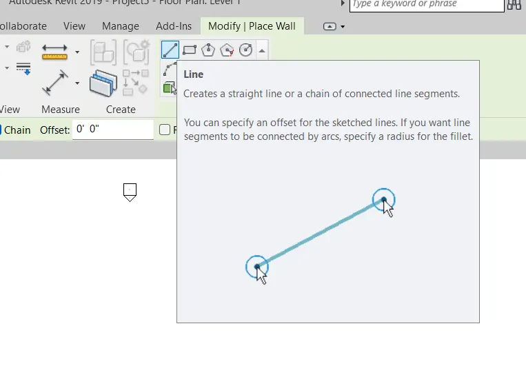
Step 2:-
- The wall is creating by using a line the dimension of the wall is 40'-0"x35'-0"
- In default the size of the wall is 8" Generic
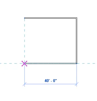
Step 3:-
- Rectangular having a dimension 40'-0"x35'-0" layout is completed
- In default the size of the wall is 8" Generic
Result:-
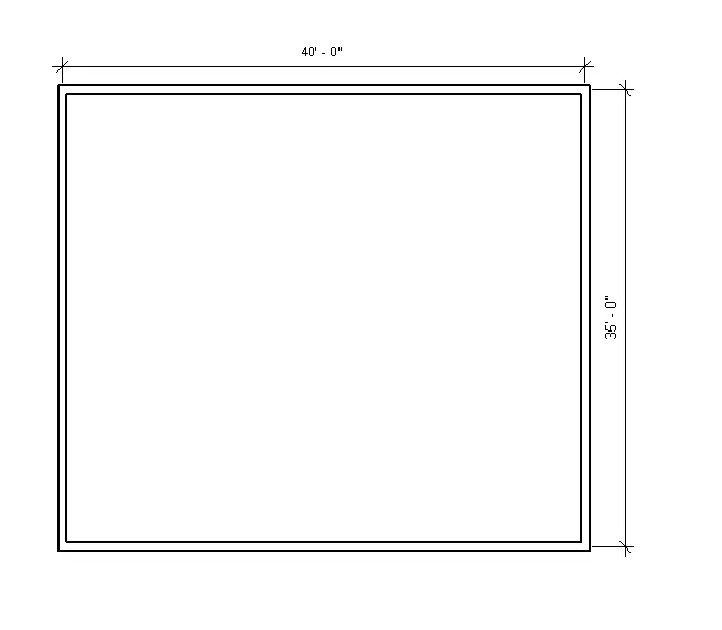
At last we will see the wall like this which has size 8" Generic and having dimension 40'-0"x35'-0"
Aim:- From annotate tool baruse the aligned option to add dimension to the layout
Procedure:-
Step1 :-
- This is the drawing of Question 3
- Go to the annotate option select any one aligned or linear tool to measure the dimension
- Click on the wall from one end to another end which dispalys blue dot
- Then it shows the dimension including wall
- To show proper dimension click on the second blue dot in the dimension
Result:-
At last the dimension is visible as shown above
Aim:- Use property browser to switch to different wall types
Procedure:-
Step1:-
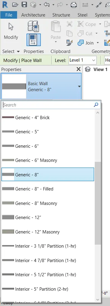
- By using a property browser change the wall thickness or wall type
- Change the wall type from 8" Generic to 5" Generic at the left
- Change the wall type from 8" Generic to 12" Generic at the right
- Keep the wall type to 8" Generic at the top and bottom
Different wall sizes
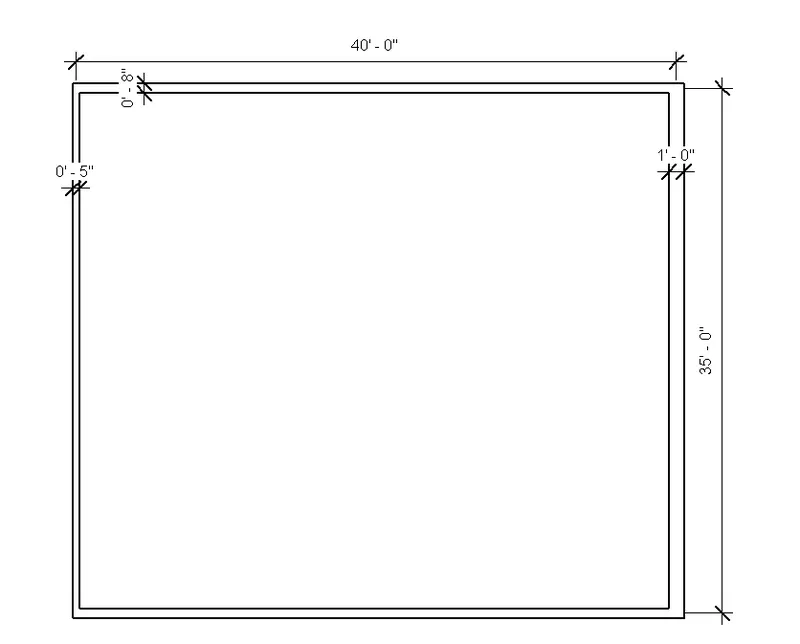
At last we will see the different wall type having 5", 8" and 12" as shown
Result:-
At last we will see the different wall type having 5", 8" and 12" as shown
Aim:-Create a 3D view from view tool bar and save the name with appropriate name
Procedure:-
Step1:-
- This is the drawing of Question 3
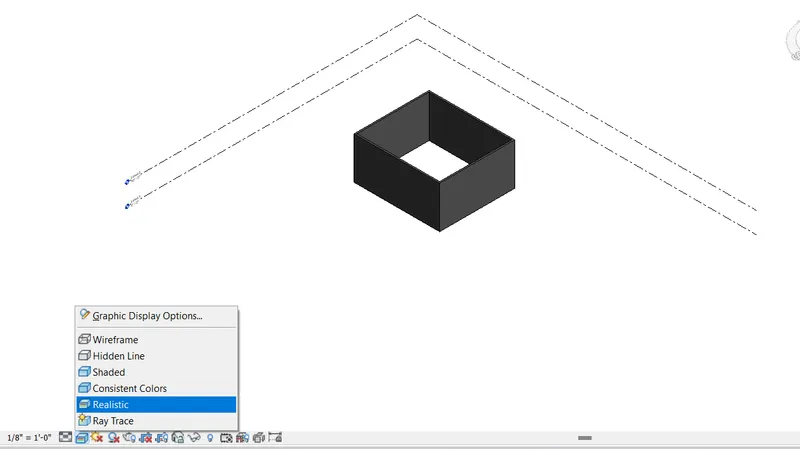
- Click on the view menu and then click on the 3D view
- After that change the view style to realistic
- Then you will get like this
Step 2:-
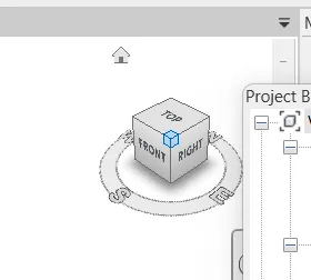
- By using a view cube change the direction of the vie wwhich you want
- It may be top, bottom, left, right, front, back and corners of the view SE, SW, NE, NW
Step 3:-
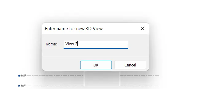
- Right click on the view which you need
- Then go to the save image option
- Name the view as your wish
- The name of the image view is show below in snap shot
Step 4:-
- The different views are saved in the name view 1 and view 2
- The 2 views snap shot are inserted below
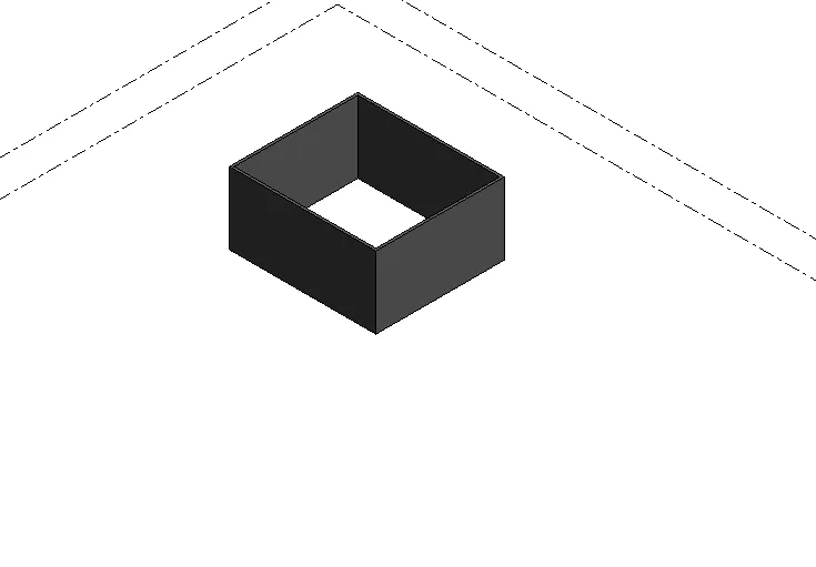
This is for the view 1

This is for the view 2
Result:-
This is for the view 1
This is for the view 2
Aim:- Navigate through the 3D model using the view cube. Orbit/pan through the model layout created
Procedure:-
Step 1:-
- This is the drawing of Question 3
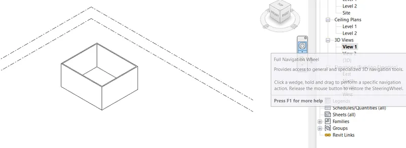
- To get the navigation click on the navigation wheel which is present below the view cube
- Click on the full navigation wheel to get the 3D navigation tool
Step2:-
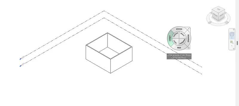
- After clicking on the navigation wheel the 3D navigation tool bar is dispalyed
- It consists of a diffrent options like zoom, orient, pan and rewind
- Inside these options 4 different options are present they are center, walk, lock, up/down
Step3:-
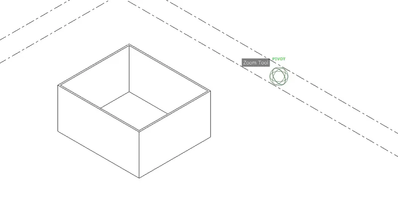
- Click on zoom option then you can zoom in or zoom out the 3D model
- The pivot point is showing to controals the zoom option
Step 4:-
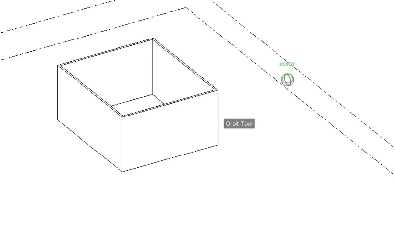
- Click on orbit option then you can change the direction of the 3D model
- The pivot point is showing to controals the orbit option
Step5:-
- Click on pan option then you can move any direction in the 3D model
- The hand symbol helps to controals the pan option
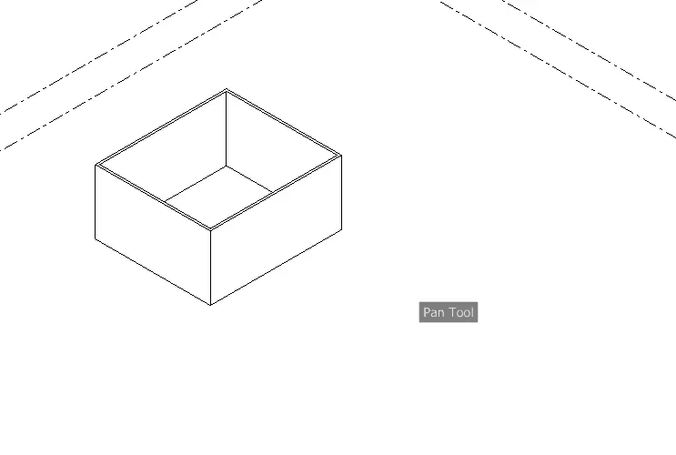
Result:-
Here zoom, orbit and pan option used snap shots are inserted
Aim:- Use the visibility setting option below to switch model to shaded, realistic and hidden line option
Procedure:-
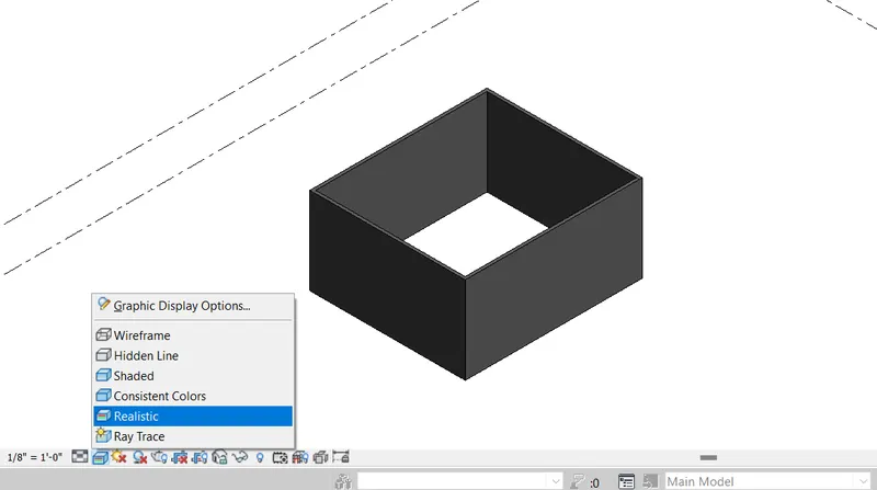
Step1:-
- This is the drawing of Question 3
- Click on the view menu and then click on the 3D view
- After that change the view style to realistic
Step2:-
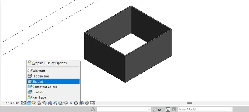
- Click on the view menu and then click on the 3D view
- After that change the view style to shaded
Step 3:-
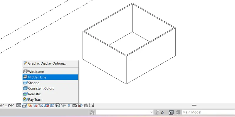
- Click on the view menu and then click on the 3D view
- After that change the view style to hiden lines
Result:-
This is the different view style like realistic, shaded and hidden lines of the project
Aim:- Turn the sun path on and off to view shading in the layout created
Procedure:-
Step1:-
- This is the drawing of Question 3
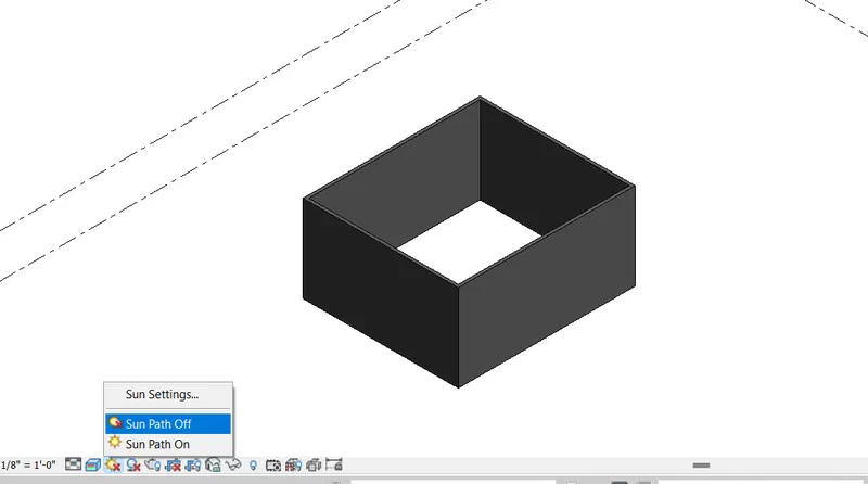
- Click on the sun path which is at the next to the view style to turn on and off
- In default the sun path is off
Step2:-
- To turn on the sun path click on the sun path on in the sun path option
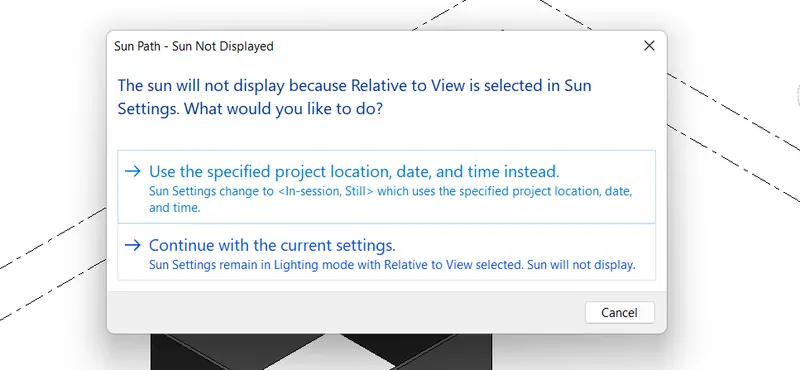
- Then you will get the sun path dialouge box
- Click on the continue with the current settings
Step3:-
- After clicking on the continue with the current settings the sun path appears
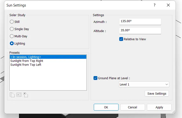
- If you want to change the setting go to the setting which is above the sun path on and off
- Then you will get like this
- This is the default setting
- If you are comfortable with this click on OK
Step4:-
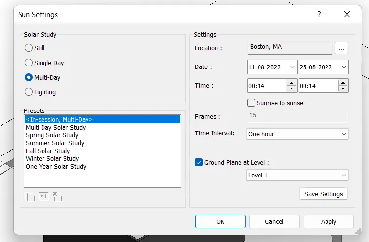
- If you need any changes in the setting go to multiday, single day or still which you want
- Here you can change the location, date, time, time interval, presets
- If you are comfortable with this click on OK
Step5:-
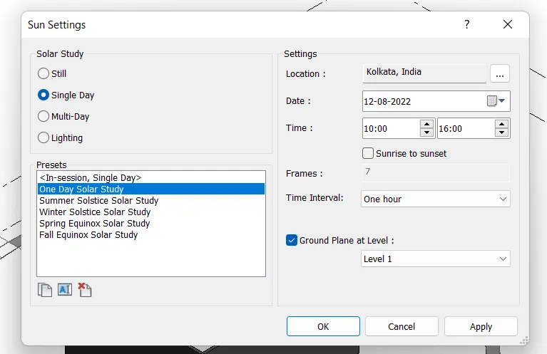
- Here I have taken single day in the setting
- Here you can change the location, date, time, time interval, presets
- These are the setting that I have changed
- Here I have selected one day solar study
- Click on OK
Step6:-
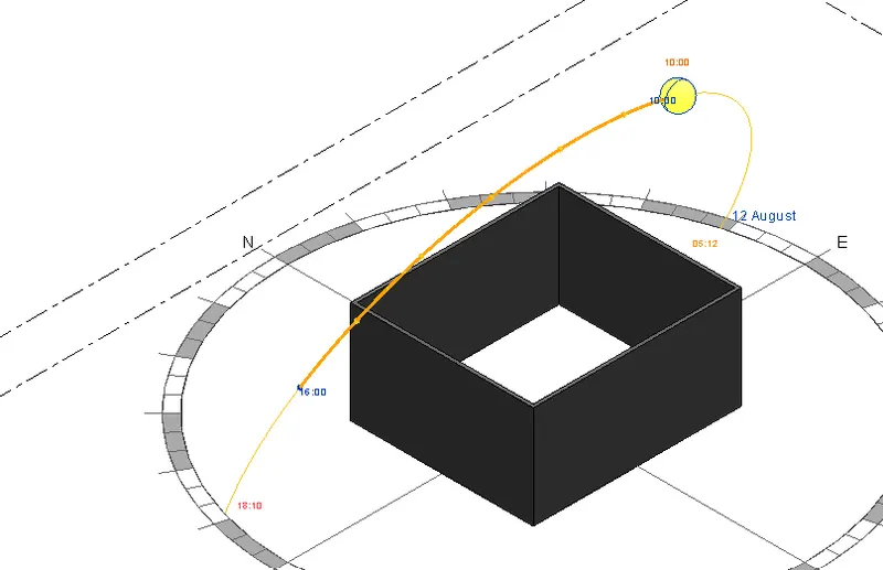
- After all these setting the sun path will look like this
Result:-
Sun path after all the settings
Aim:- Use manage tool bar to enter project setting, project name and project issue date
Procedure:-
Step1:-
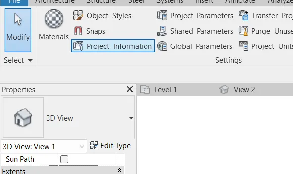
- Click on the manage tool bar then you will see lot of options like materials, object style, snap, project information ect.,
- In that select the project information to add the information of the project
- These informations are visible in Properties
Step2:-
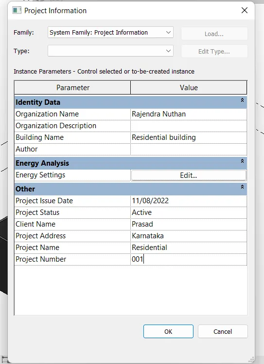
- Click the project information then this dialouge box will open
- Here the information is edited which is in snap shot
- After the edit click on OK
Result:-
At last we will get this information in the properties
11. What is analyze tool bar used in Revit? How it is beneficial for design and modelling
- Analyze tool bar is used for analysis of a structural building.
- Analyze tool bar consists of a different elements like boundary condition, loads, load cases, load combination etc.,
Boundary condition
- In boundary condition helps you to define points, lines and area boundary condition in an analytical model
- It will verify the boundary condition and family types are loaded and assigned to your structural model
Loads
- In the same manner we can apply point, line and area loads to the model
Load cases and Load combinations
- In the same manner we can edit and add the load cases to provide the standard load cases to the model by using a code books
- We can add more number of loads by using load combination
- It helps to add load combination for analytical model
- Here we are evaluating the energy or energy optimization of a building model

12. What are the links that Revit supports to be linked to the model
Link Revit
- This allows to link another Revit model to the current model
Link IFC
- This allows to link the IFC file to the curent model
Link CAD
- This allows to link 2D CAD file to the current Revit file to create 3D model
Manage links
- Provide features of the manage the links to the building model
- For example :- If we are linking the plumbing and structural model, then If we want to remove the plumbing from the strctural model, Go to the manage link and unload the model you dont want

13. Why do you need collaborate tab in Revit? How it supports madeling and its efficiency
- The collaborate tab in the Revit helps to collaborate the structural model with the team members who are using this software
- This also helps to link the multiple Revit model together
- Through work sharing users on the same local area(LAN) can work together in same Revit model
- Use Revit server and Work sharing when the users are not in same local area (LAN)
