Week 3 Challenge
Aim:- To provide the primary load cases fro design, defination for one way slab, unit weight of structural steel and soil, name of few sections, define primary beam.
1. 1. State the primary load cases to be considered for design.
The primary load cases are
- Dead load (IS 875:part 1)
- Live load (IS 85:part 2)
- Wind load (IS 875: part 3)
- Seismic load (IS 1893:2016
2. What is One – Way slab?
- The ratio of longer span to shorter span is greater than 2 is called one way slab
ly/lx >2
Where,
- ly - Longer span
- lx - Shorter span
3. What is the value of unit weight of structural steel and soil?
- Unit weight of structural steel is 7850 Kg/m^3
- Unit weight of Soil is 18 KN/m^3
4. Name few sections that can be defined using Properties tab in STAAD Pro.
Name of the sections are
- Circular section
- Rectnagular section
- Tee section
- Trapezoidal section
- General section
- Tapered I section
- Tapered tube section
- Assign profile section
5. Define Primary Beams.
- The beams which are directly connected with columns on both the ends are called Primary beams
- The role of this beam is to transfer the load to column
- The load comes from slab then transfers to secondary beam is it's present then transfers to primary beam then transfers to column
Result:-
The answers are written in detail for
- primary load cases fro design
- defination for one way slab
- unit weight of structural steel and soil
- name of few sections
- define primary beam
2.
Aim:- To state the factors and parameters for design pressure, mentioning load transfer process
2. 1. State the factors and parameters that influence the design pressure intensity of a high-rise building.
The factor that influence the design pressure intensity of high rise builidng are
- k1 - Probability factor (risk co-efficient)
- k2 - terrain, height and structure size
- k3 - topography factor
- k4 = Importance factor for cyclonic region
Design wind pressure
Design wind pressure is obtained by the relationship between the wind pressure and wind velocity
Pz = 0.6xV^2
2. Mention the load transfer process of a Reinforced Concrete Building.
The load transfer process of a Reinforced Concrete Building are
- Slab
- Secondary beam
- Primary beam
- Column
- Footing
Result:-
The answers are written in detail for
- State the factors and parameters for design pressure
- Mentioning load transfer process
3.
Aim:- To differentiate the one way and two way slab, explaination about the secondary beam, mentioning of primary load cases, steps involved in assigning proerties and support to a model, step to follow to create the secondary beam
3.1. Differentiate One-Way and Two way slabs. Elaborate each slab type.
| One way slab | Two way slab |
|
|
|
|
|
|
|
|
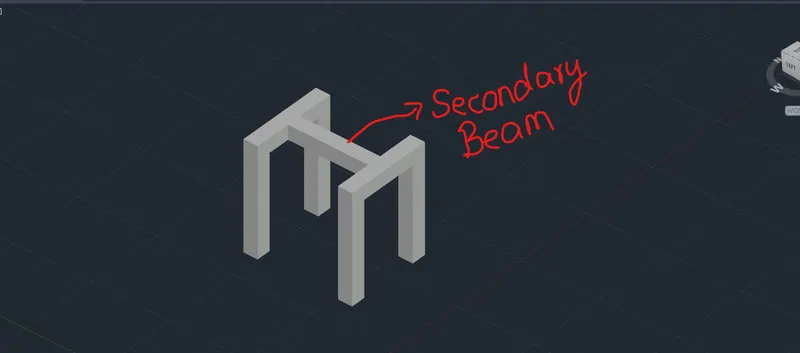
2. Explain the concept of secondary beams with proper sketch.
- Secondary beams are connected with main primary beams, these beams acts as a simply supported beam
- In the secondary beam the moment at the end support is zero
- Secondary beam carry certain amount of load from the slab then transfer into the primary beams
- Secondary beams carry only the shear not moments
3. Mention the Primary load cases.
a. State the Indian Standards for each load case
b. Detail the parameters of each load case
c. Brief each load case
a. State the Indian Standards for each load case
- Dead load (IS 875:part 1)
- Live load (IS 85:part 2)
- Wind load (IS 875: part 3)
- Seismic load (IS 1893:2016
b. Detail the parameters of each load case
- Member load
- Concentrated load
- Floor load
- Plate load
c. Brief each load case
Dead load :-
- Dead load is a permanent load on the structure which is a self weight of the structure
- This load is caused by the beam, column, slab, footing loads
- This load is calculated by using the IS 875 Part 1
Live load:-
- This loads are fully or partially vary from time to time on the structures
- This loads are not constant throughout the life span of the structures
- Live loads varies based on type of structures
- This load is calculated by using the IS 875 Part 2
Wind Load:-
- Wind load is a load on the structure which is generated by the wind
- Wind load is an important load, we must and should consider the wind load in the hilly region
- In the normal flat region also we consider the wind load when the height of the structure is above 15m
- This load is calculated by using the IS 875 Part 3
Seismic load:-
- We should consider the seismic load for the analysis and design of the high rise building
- We consider this load where the chance of earthquake occur is normal and also we consider this load in the earthquake prone areas.
- As per the IS code we carried out the dynamic seismic analysis by two methods they are Spectrum analsyis and Time history method
- This load is calculated by using the IS 1893:2016
4. Detail the steps involved in assigning Properties and Support to a model using STAAD Pro sequentially.
Steps involved in assigning Properties and Support to a model using STAAD Pro are
Assigning Properties
- After creating the geometry then go to the property tab
- Click on the define material
- Select any one of the section weather it may be Recatngular, Circular, Tee etc.,
- Select the material for the section weather it may be Concrete, Steel, Aluminium etc.,
- If the Rectangular Section is selected then provide the dimensions to the section
- Then select the material for the rectangular secction
- Then click add and close
- Click on the Property then assign to the selected view
For Supports
- Click on the support tab
- Then click on the create
- Then select the type of the support we want to provide
- Click on add then close
- Then click on assign to the view property
5. Brief the steps to be followed to create and assign secondary beams in STAAD Pro
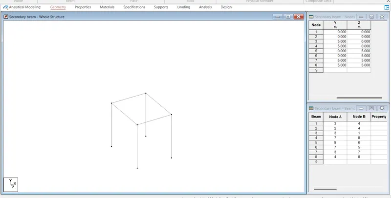
Step1:-
- Create the model by providing the name, units
- Then the modelling screen opens then click on the geometry
- Then create the nodes by using the X,Y and Z co-ordinates
Step2:-
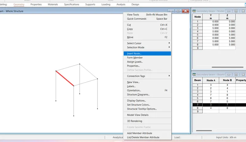
- After creating the nodes from the co-ordinates
- Then select the beam then click right button of the mouse
- Then click on the insert node to provide the secondary beam
Step3:-
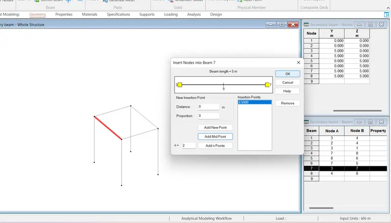
- After selecting the insert node then insert node into beam dialouge box opens
- Click on the add mid point then click on OK
- Repeat this procedure for another beam also
Step4:-
- After creating the beam node in the mid point
- Draw the beam which connects mid point of one beam to another beam
- This is called secondary beam
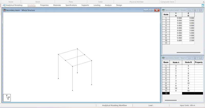
Step5:-
- After creating the secondary beam
- Go to the property tab then click on the define
- Then property dialouge box opens then select the Rectangle
- Provide the dimension as 0.23x0.23
- Then click on add
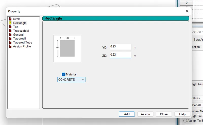
Step6:-
- After adding the property then select the properties
- Then click on the assign to selected beam
- Then click on assign
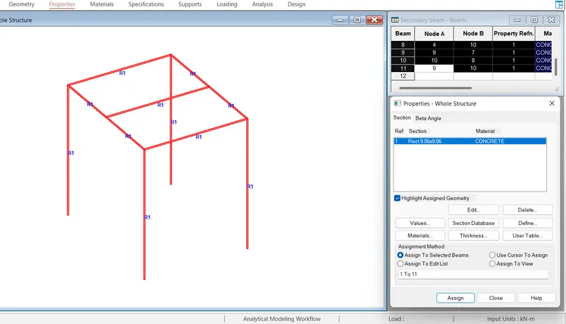
Step7:-
- After assigning the property then provide the material
- Go to the material tab select the concrete
- Click on assign to view
- Then click on Assign
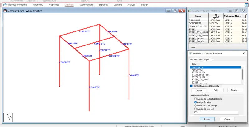
Step8:-
- After providing the material then assign the supports for the column
- Then provide the dead load, In dead load provide the Self weight
- Then provide the live load, In live load provide the floor load
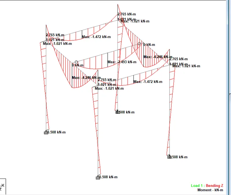
- Then analyse the model then we will see the secondary beam carries the hogging moment so we need to release the moment
- Then go to analytical model then go to specification then release the beam force (Fx) and Moment (Mz)
- Then anlyse the model then we will get the 0 moment at the support
Results:-
The answers are written in detail for
- Differentiate the one way and two way slab,
- Explaination about the secondary beam,
- Mentioning of primary load cases,
- Steps involved in assigning proerties and support to a model,
- Step to follow to create the secondary beam
Practical
1. Calculate the wind pressure for the given building
a. Building Dimension : 20m x 30m x 20m height RCC
b. Building usage : Hospital block in city centre
c. Location : Darjeeling
From IS 875 Part - 3 2015
Design wind speed (Vz)
Vz = Vb x k1 x k2 x k3 x k4
Where,
Vz = Design wind speed at height z in m/s
k1 = Probability factor (risk co-efficient)
k2 = terrain roughness and height factor
k3 = Topography factor
k4 = Importance factor for cyclonic region
From Annex - A the wind speed is 47 m/s for Darjeeling
From table 1 wkt hospital builidng is a Important builidng and design life of structure is 100 years
So for 47m/s wind speed k1 = 1.07
To find k2 first we have to see the category of building which it lies
our builidng lies in Category 4
Height of the building is 20m
From table 2 for the category 4 and 20m height k2 = 0.80
From topography factor k3 = 1
From importance factor for cyclic region k4 = 1.3
Vz = Vb x k1 x k2 x k3 x k4
Vz = 47x1.07x0.80x1x1.3
Vz = 52.30m/s
Calculation of wind pressure
Pz = 0.6 x Vz^2
Pz = 0.6x52.30^2
Pz = 1641.174 N
Pz = 1.64 KN
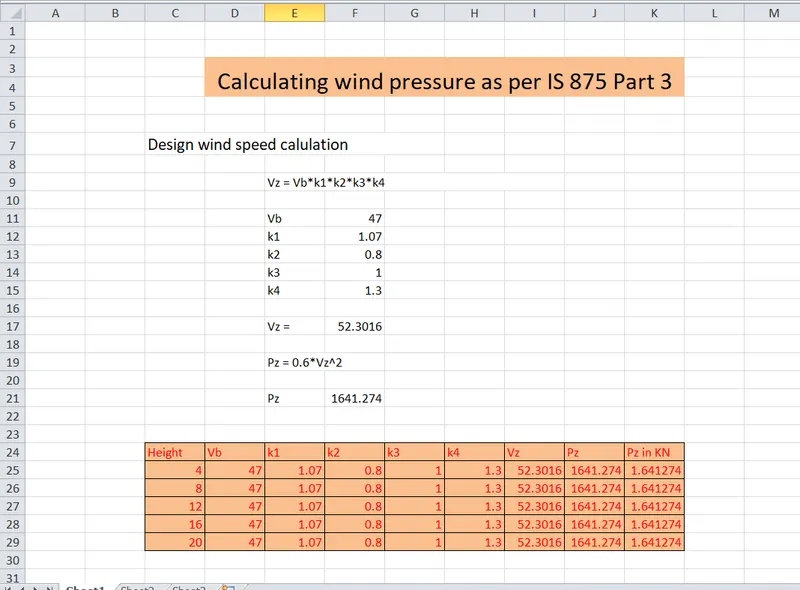
Here we can calculate for different height
2. Calculate the Dead load and Live load for the above building with reference to IS standards ( assume suitable sections )
Calculating Dead laod for the slab
Assume the thickness of the slab is 150mm
Dead load for the slab = Thickness x unit weight of RCC
Length = 20m
Breadth = 30m
Dead load for the slab = Thickness x unit weight of RCC
= 0.15x25
= 3.75 KN/m^2
Calculating dead load for beam
Assume the beam dimension is 300x500mm
Assume the length of the beam is 10m
Dead load for the beam = Volume x unit weight of RCC
= 10x0.3x0.5x25
= 37.5KN
Calculating dead load for partition wall
Assume,
Unit weight of brick = 20KN/m^2
Height of the wall = 3m
Width of the brick = 0.3m
Partition wall width = 0.15m
Length of wall = 10m
Dead load for partition wall = Area of brick x Unit weight of brick
= Thickness of wall x Height of wall x unit weight of brick
= 0.15x3x20
= 9 KN/m
Live load
Calculating live load as per IS 875 Part 2
Occupancy Live load
For wards, dressign rooms and lounges 2 KN/m^2
Kitchen and labratories 3 KN/m^2
Dining room and cafeterians 3 KN/m^2
Toilets and bathrooms 2 KN/m^2
X-ray rooms and Operating rooms 3 KN/m^2
Office room and OPD rooms 2.5 KN/m^2
Corridors, passage, lobbies and stairs 4 KN/m^2
Result:-
The answers are written in detail for
- Calculate the Dead load
- Calculate the Live load