Reinforcement Detailing of Beams from ETABS output
Introduction:-
Seismic force :- It is the external force applied to the structure as a result earthquake generated agitation
- In this the earthquake occured at once in a 2500 years
- Seismic cannot be determined it's a less uncertainity
- Seismic force occure at the ground level in all the directions and it has 3degree of freedom they are 2 translational and 1 rotational force
- The base shear starts at the bottom of the buildings when the seismic load occures
ETABS :-
- The full form of ETABS is Extended three dimensional analysis of building system
- ETABS software was started by CSI (Computers and Structural ,Inc
- ETABS is a engineering software which is used for multistorey analysis and design
- In this software we can analyse and design the seismic load, wind load, and other loads
- In this software we are defining and assigning the materials, frame sections, slab sections diaphragm etc.,
- This software give the proper output result to that analysed model
- In this question the model is given in the question itself so we need to analyse and design the frame structures
- By using an AutoCAD draw the detailing of the beam
Answers along with procedure:-
Detailing rule of any reinforced concrete member
- Minimum reinforcement for shrinkage and temperature
- Reinforcement required for limiting crack width
- Ultimate limit state design rebar requirement
- Ductility rebar requirement
Which ever is greater should be drawn in detailing
Minimum longitudinal reinforcement as per IS 13920-2016 clause 6.2.1 As = 360mm^2
Minimum shear (or) trnasverse reinforcement as per IS 456:2000 clause 26.5.1.6 (Assuming 1000mm spacing in the formula) Asv = 332mm^2
Development length as per IS 456:2000 clause 26.2.1 Ld = 41xdiameter of the bar
ETABS design Procedure:-
Step1:-
- The ETABS model file is given in the question
- Open the file in a ETABS software
- Click on the Run analysis
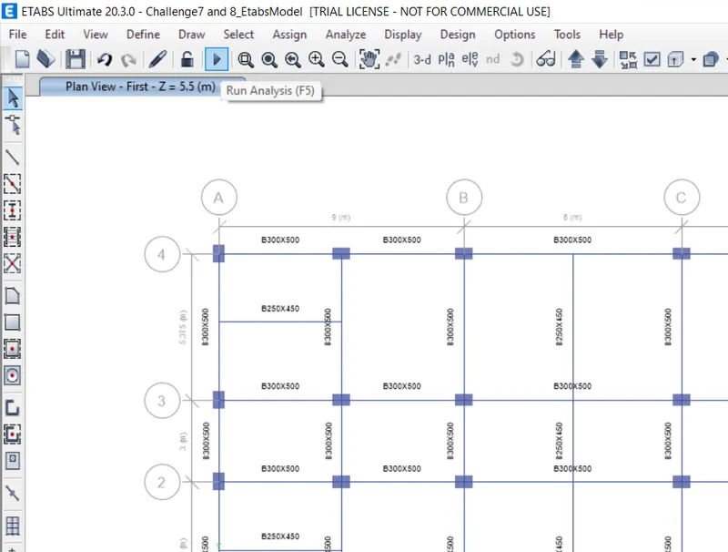
Step2:-
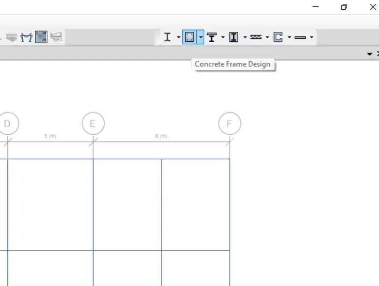
- After the analysis complete then click on concrete frame design
- And wait for some times it will give the details about reinforcement, shear, bending moment etc.,
Step3:-
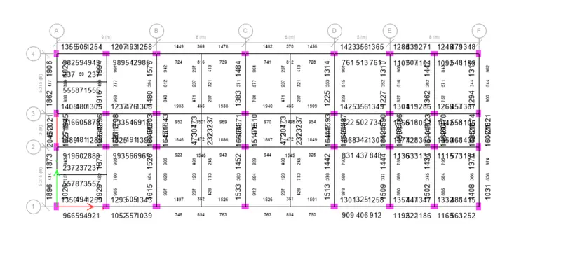
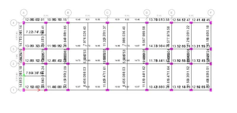
- When the concrete design has done then it shows the longitudina reinforcement
- This is the snap shot of the longitudinal reinforcement required
Step4:-
- After the longitudinal reinforcement
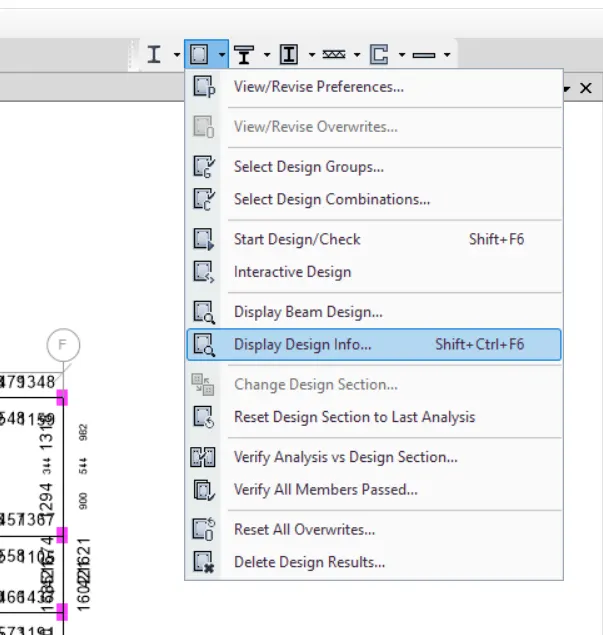
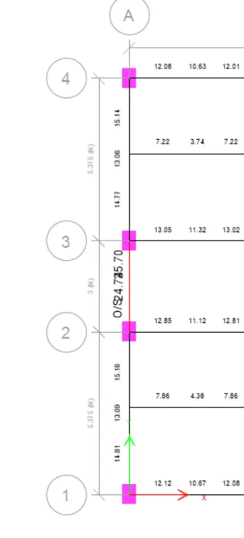
- To see the shear reinforcement Go to the concrete design then go to the display design information
- Then select the shear reinforcement it shows the shear reinforcement values
- The snap shot is inserted below
Step5:-
Longitudinal reinforcement of the beam at Grid A from ETABS (mm^2)
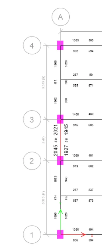
Shear reinforcement of the beam at the Grid A from ETABS (cm^2/1000)
Step6;-
Longitudinal reinforcement of the beam at Grid 3 from ETABS (mm^2)

Shear reinforcement of the beam at the Grid 3 from ETABS (cm^2/1000)

Additional reinforcement guidelines from the IS 13920-2016 clause 6
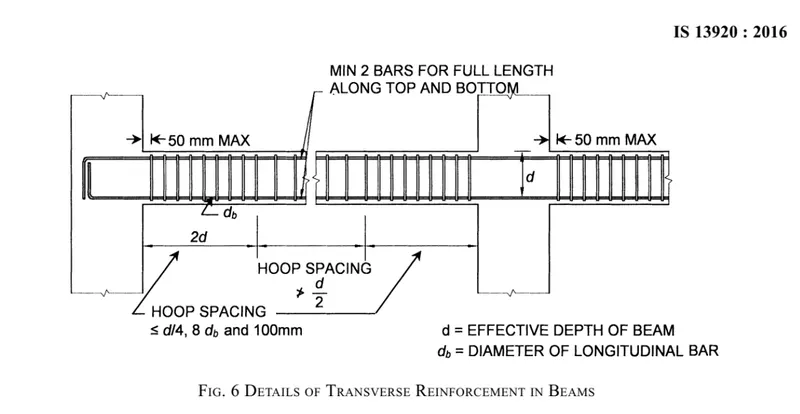
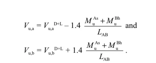
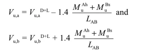
As per IS 13920-2016 clause 6.3.3(b) the sway shear force is given
Step7:- Sway shear force at right
Sway shear force at left
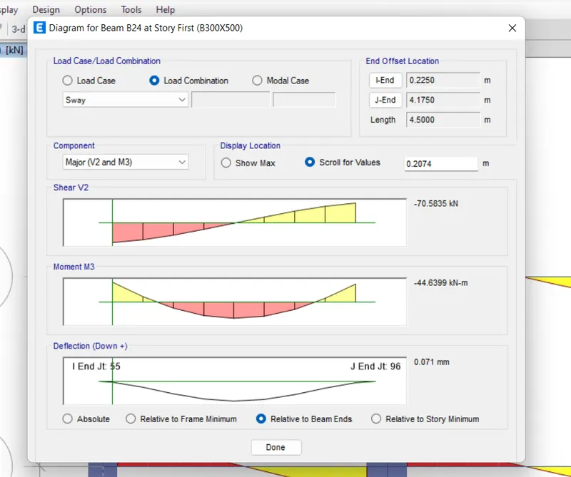
The value of Vua D+L is 70.5835 is taken from the ETABS model
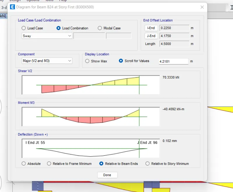
The value of Vub D+L is 70.333 is taken from the ETABS model
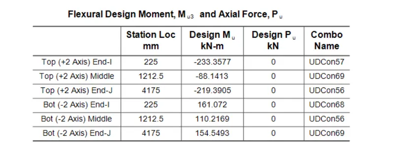
Here the value of Mu As , Mu Bh , Mu Ah , Mu Bs are given by the ETABS model
+ve reprsesnts - Sagging
-ve represesnts - Hogging
- Mu As = 161.072 KN-m
- Mu Bh =219.3905 KN-m
- Mu Ah = 233.3577 KN-m
- Mu Bs = 154.5493 KN-m
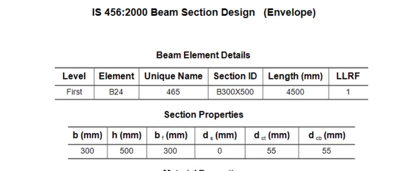
Here the length is given as 4500mm by the ETABS
so the LAB = 4500mm
Here the calculation is done according to the formula
|
Vua D+L |
Vub D+L |
LAB in m |
Sway to Right |
Sway to Left |
||||||
|
Mu As |
Mu Bh |
Vua |
Vub |
Mu Ah |
Mu Bs |
Vua |
Vub |
|||
|
70.5835 |
70.333 |
4.5 |
161.072 |
219.3905 |
47.78 |
188.69 |
233.3577 |
154.5493 |
50.09 |
191.015 |
Compare Vua on both left and right sway then take a hiighest value in that
Compare Vub on both left and right sway then take a hiighest value in that
Vua = 50.09KN
Vub = 191.015KN
Here we are using 3L-8mm dia bars at 100mm c/c at the support and 3L-8mm dia at 175mm c/c at the midspan
Step8:- Detailing for beam along A-1 to A-3
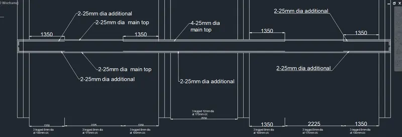
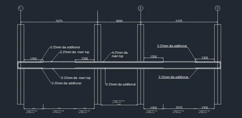
This detailing drawing is for A-1 to A-3
Detailing for beam along 3-A to 3-B
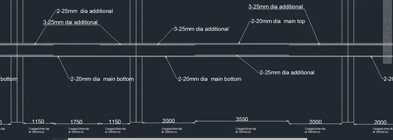
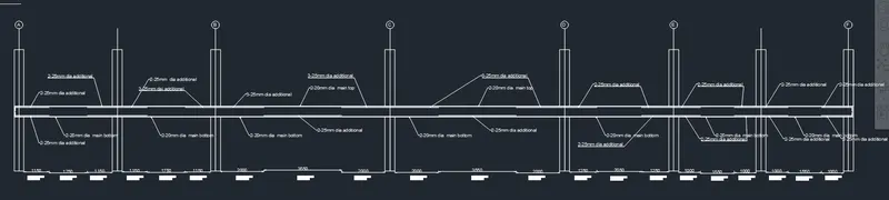
This detailing drawing is for 3-A to 3-B
Result:-
- As per the given data the beam detailing is done by using AutoCAD
- The details of longitudinal and shear reinforcement are done for both the continuous beams
- The details of longitudinal and shear reinforcement in ETABS also calculated
Shear stress :- It is the ratio of the load applied to its unit area
- In the shear stress we can increase the load and decrease the load so that we can increase and decrease the shear stress
Shear capacity of the concrete
- It depend on the characteristic strength of the concrete
- The shear capacity varies with the grade of the concerete
- Instead of using a M-20 grade to this failing structure we can use high grade of the concrete only for this concrete only (M-25 or M-30)
- So that we can increase the shear capacity of the beam
- Hence the failing structure become safe