Reinforcement detailing of Columns from ETABS output
QUESTION :
Reinforcement detailing of columns in Etabs 2018.
The ETABS file for a G+4 building is provided. Run the analysis and design the RCC Moment Resisting Frame. The following challenge deals specifically with two columns at the following grid intersections.
- 3A
- 3B
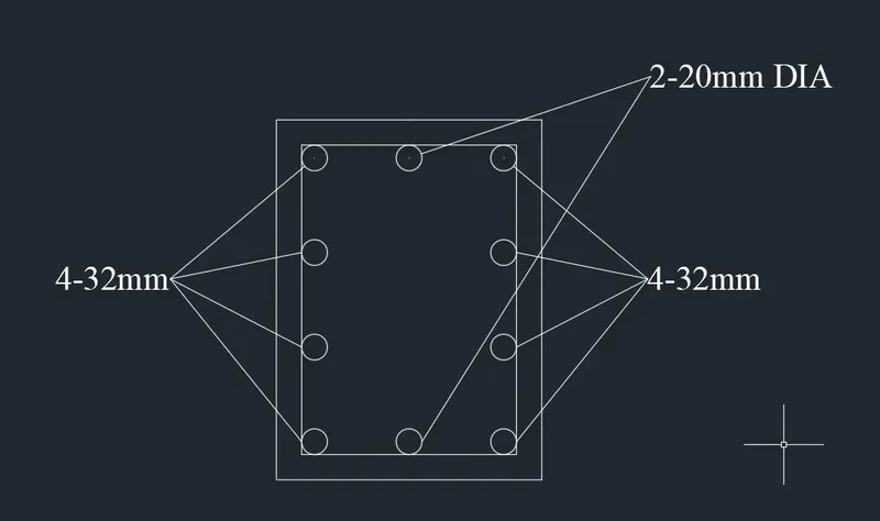
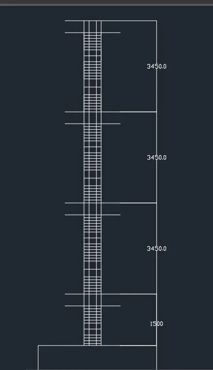
- Provide details of longitudinal reinforcement for the two columns, from foundation to terrace level. Sketch the column cross sectional & elevation details or draft it using autocad software.
- Show shear reinforcement & lapping details as per special confining reinforcement provision of clause 8.1 of IS 13920 - 2016.
ANSWER :
AIM :
To ETABS file for a G+4 building is provided. Run the analysis and design the RCC Moment Resisting Frame. The following challenge deals specifically with two columns at the following grid intersections.
INTRODUCTION :
As per IS code, the minimum dia of the longitudinal bar should not be less than 12 mm, and the dia of a stirrup should not be less than 8 mm. Stirrup should be placed at a distance of 150 mm (centre to centre distance).
Vertical bars of Columns shall be lapped in regular zone (Mid-height ) only and it should be staggered i.e. not more than 50% of bar can be lapped at one section. In addition to that minimum clear vertical distance between lapped bars shall be 0.25 times lap length.
ETABS software is used for the analysis of concrete shear walls and concrete moment frames. It is highly acclaimed for static and dynamic analysis of multi-storey frame and shear wall buildings.
PROCEDURE:
STEP 1:
- Open the etab and select the previous project and save as new.
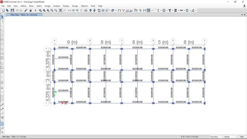
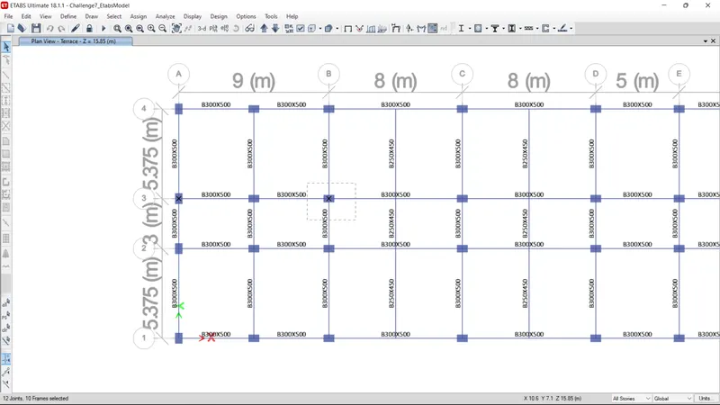
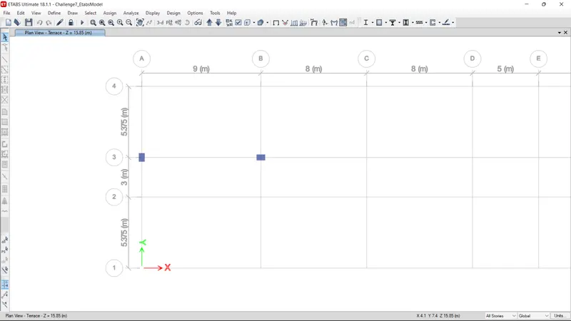
- Select the 3A and 3B column.before that set the all stories and then select.
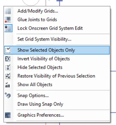
- Then right click and select the " show selected objects only "
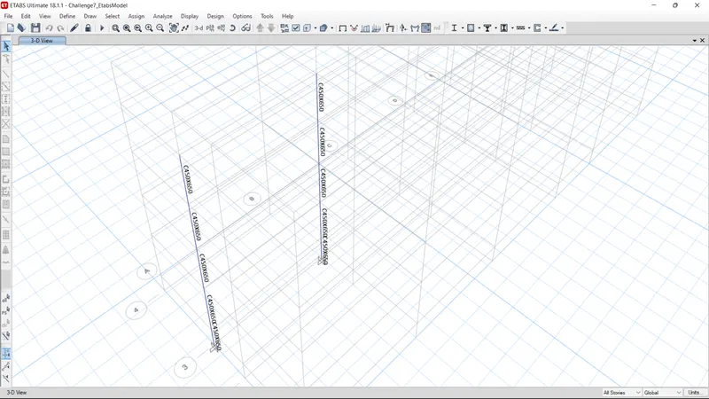
- After that all the other materials are temporarly hide
- the hiding image as shown below
STEP 2:
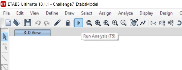
- Just analysis the model with using of run analysis option or use f5 option
- After analysis the values are shown in the column
- Next we go to the elevation option
- set elevation view dilaouge box as been open
- Pick the '3' option and then apply
- The elevation views are shpwn below in the image
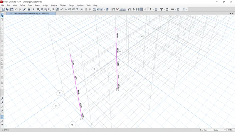
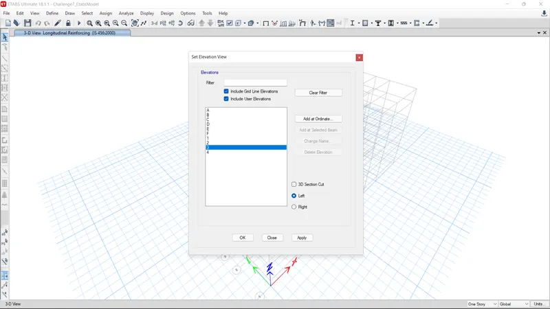
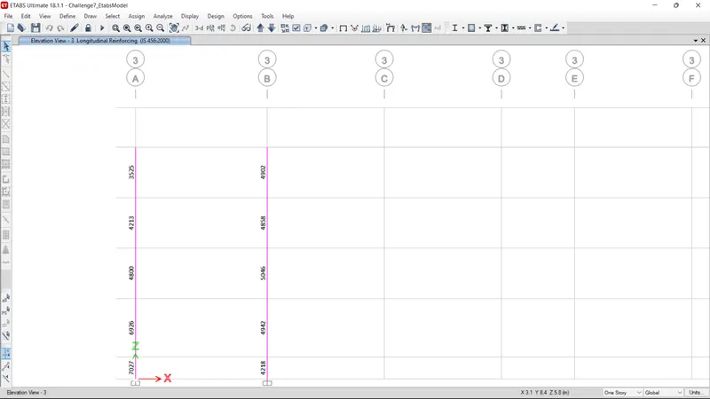
STEP 3:
- Next we go to the concrete frame design
- And select the display design info option
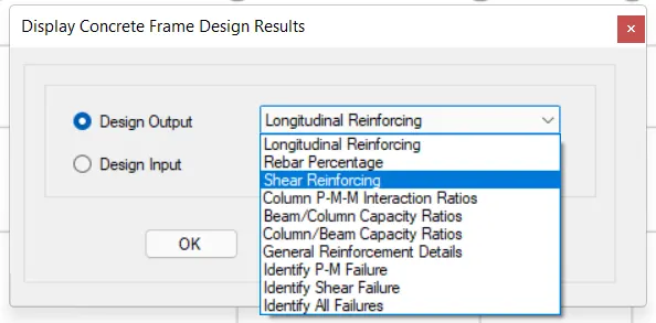
- And go to design output
- select the longitudinal reinforcing
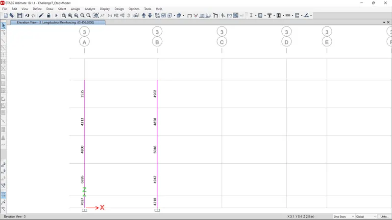
- longitudinal reinforcing values are shown in the image
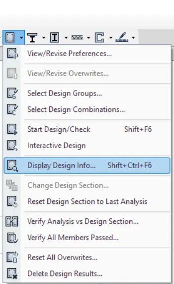
STEP 4:
- After select the shear reinforcing in the same dialouge box
- And then apply
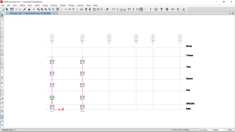
- the shear reinforcing values are shown below
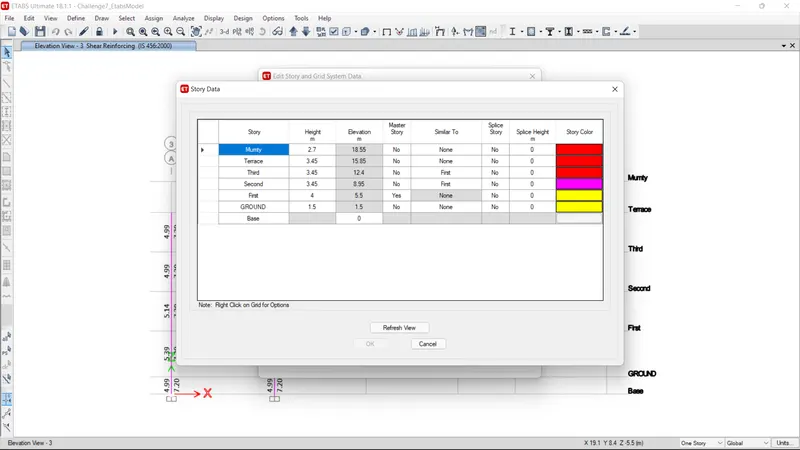
- Go to the edit tool bar and select the edit storey grid
- the story height values are shown there
RESULT :
1.Column 3A :
Maximum Ast = 7027mm2
Provide 8 bars of 32mm = 6446 mm2
And 2 bars of 20mm = 628 mm2
Provide the 10mm stirrups with the 150mm for Zone C
As the width is greater than 300mm confining reinforcement is provided in both the direction.
2.Column 3B :
Maximum Ast = 5046mm2
Provide 8 bars of 28mm = 4920 mm2
And 2 bars of 12mm 226 mm2
Provide the 10mm stirrups with the 150mm for zone C