To plan a structural layout and to create grids using TSD
1. Summarize the user interface in TSD with the for the following items: -
- Project Workspace – How to access and usage
- Scene Content – Demonstrate the use of scene content
- Create two scene views
- Loading drop list- How to access
- Properties windows – how to access and usage
AIM :
To Summarize the user interface in TSD with the for the following items
INTRODUCTION :
Tekla Structural Designer is an integrated model-based 3D tool for analysis and design (of both concrete and steel members) in multi-material structures.
Features include interactive modeling, automated structural analysis and design, drawing, and report creation.
Multiple design codes are supported:
-
ACI/AISC
-
Eurocodes
-
British Standards
-
Indian Standards
-
Australian Standards
The aim is to allow you to rapidly build your model, apply loads, and design the model for an appropriate set of design forces.
On a day to day basis, you do not need to be involved with the underlying analysis models to achieve this. Instead, you can focus on the design results.
To make this possible, Tekla Structural Designer automatically creates and analyzes multiple solver models, each one being based on a different but widely accepted approach.
By designing for the forces from all the solver models, you can be confident that each scenario has been catered for.
PROCEDURE :
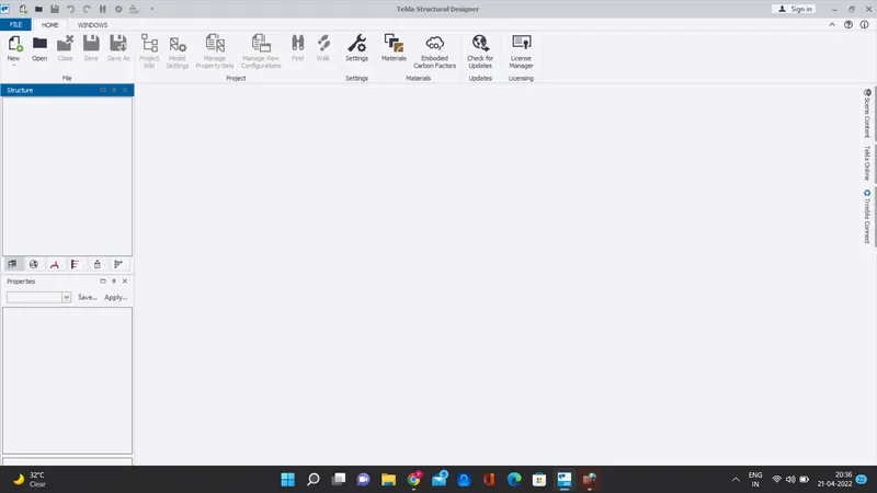
1.) Project Workspace – How to access and usage
- Open the tekla software
- Open the new file at left top corner
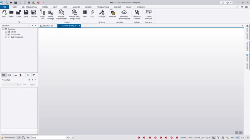
- After create a new model work space. they shown the tool bars and work tools on the screen main menu
- Also they have shown the struture template and properties template on the left side of the screen
- In the fresh screen they shown only home and windows tab on top screen
2.) Scene Content – Demonstrate the use of scene content
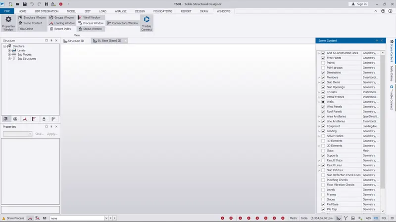
- Here the scene content option automatically shown on the right side of the screen
- The scene content option will be used for hide and visible of the materilas like grid, point, members, dimension etc...,
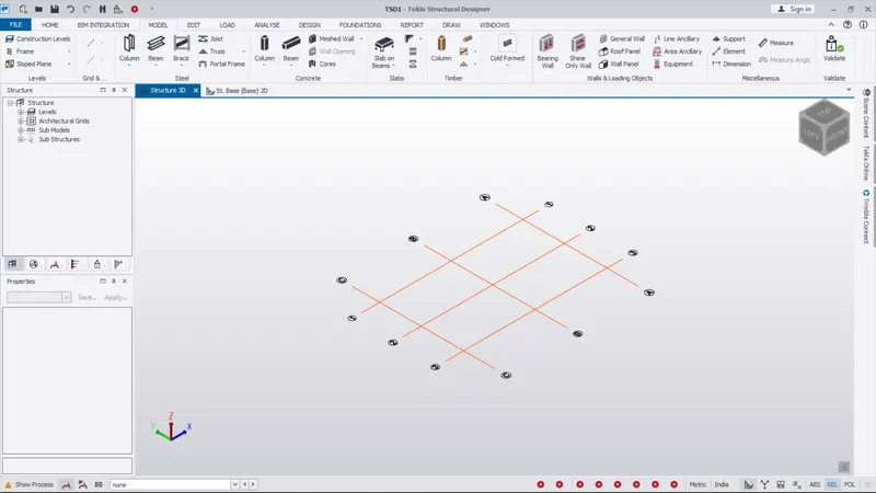
3.) Create two scene views
- When we open the tekla software the two scene views not shown automatically on the screen
- So we want to open the new file with help new option
- After the new file will be opened. the two scene views shown automatically on the screen
- And then one is 2D view
- And then onather one is 3D view template
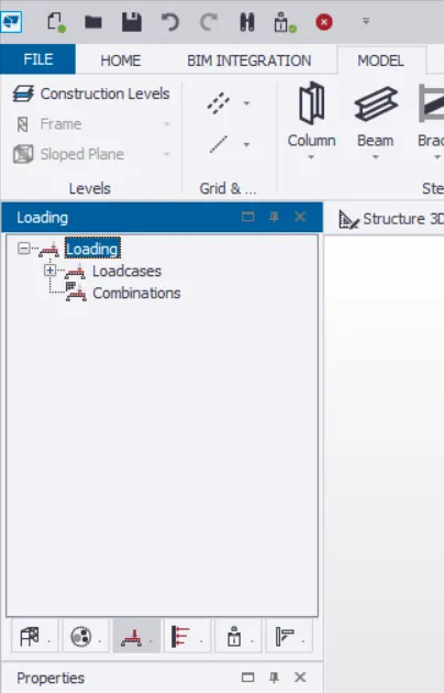
4.) Loading drop list- How to access
- After the new file has been opened
- The screen left side they shown the structure table box
- In the box they have some option on the bottom
- Use the 3rd option (Loading) to open the loading mode
- In the loading they have two types
1.) loadcasese
2.) combination
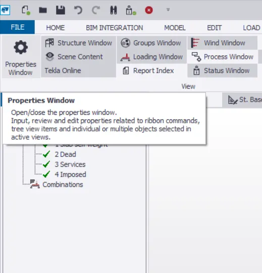
5.) Properties windows – how to access and usage
- In order to open and close the properties windows , go to the window tab and select the property window option on the left top corner and open or close it
RESULT :
As per the given question
- Project Workspace – How to access and usage
- Scene Content – Demonstrate the use of scene content
- Create two scene views
- Loading drop list- How to access
- Properties windows – how to access and usage
The given access and usage are modeled successfully
2. Create a new file in TSD and set up the settings for a steel building to have member grade FE410 and concrete grade of M30 as per IS codes. The covers for the members to be as per the following input: -
|
MEMBERS |
IN CONTACT WITH GROUND |
ABOVE GROUND |
|
Column |
50mm |
40mm |
|
Slab |
30mm |
25mm |
|
Pile cap |
75mm |
|
|
Foundation |
50mm |
AIM :
To Create a new file in TSD and set up the settings for a steel building to have member grade FE410 and concrete grade of M30 as per IS codes. The covers for the members to be as per the following input
INTRODUCTION :
Tekla Structural Designer is an integrated model-based 3D tool for analysis and design (of both concrete and steel members) in multi-material structures.
Features include interactive modeling, automated structural analysis and design, drawing, and report creation.
Multiple design codes are supported:
-
ACI/AISC
-
Eurocodes
-
British Standards
-
Indian Standards
-
Australian Standards
The aim is to allow you to rapidly build your model, apply loads, and design the model for an appropriate set of design forces.
On a day to day basis, you do not need to be involved with the underlying analysis models to achieve this. Instead, you can focus on the design results.
To make this possible, Tekla Structural Designer automatically creates and analyzes multiple solver models, each one being based on a different but widely accepted approach.
By designing for the forces from all the solver models, you can be confident that each scenario has been catered for.
PROCEDURE :
- Open the tekla structural designer software
- Click the new model option
- The project workspace is now active as shown and all the ribbons and menu bars are visible
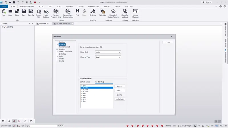
- Go to the home tab
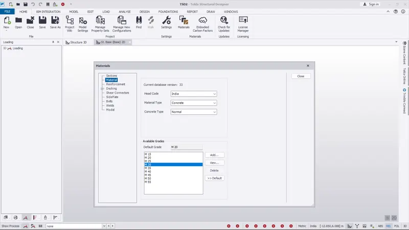
- select the material option, and select the head code india
- And select the material type steel
- Again select the material option, and select the head code india
- And select the material type concrete and concrete type normal
- Select the default grade Fe410 W/A
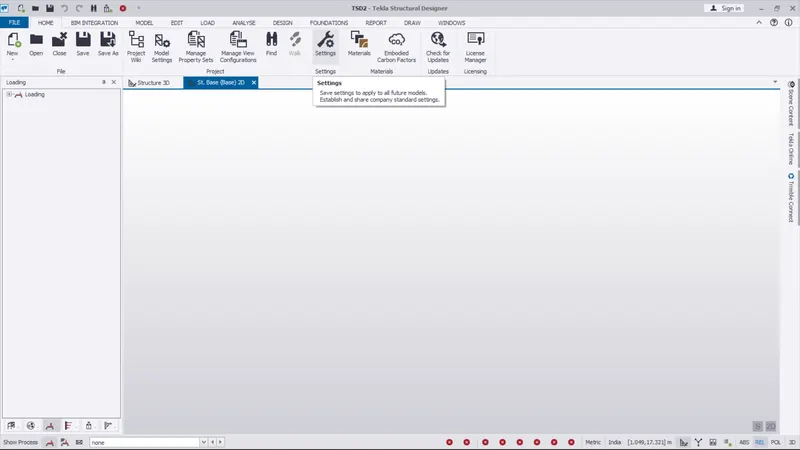
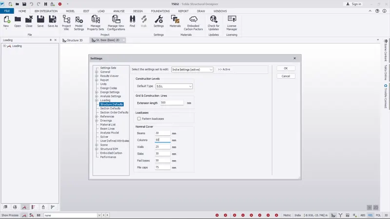
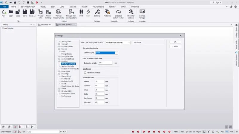
- Go to the home tab and select setting option
- And edit the values in the structure default
RESULT :
As per the given question
|
MEMBERS |
IN CONTACT WITH GROUND |
ABOVE GROUND |
|
Column |
50mm |
40mm |
|
Slab |
30mm |
25mm |
|
Pile cap |
75mm |
|
|
Foundation |
50mm |
With reference to the input drawing as per Attachment 1, 1.1, and 1.2 and study the steel building plan and summarize your understanding of the plan. Based on your study assume and explain the location of columns and beam and develop a hand sketch for each plan
The valuse of slab, pilecap, column, foundation given successfully
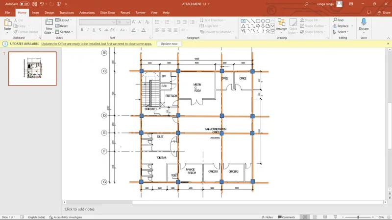
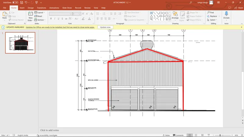
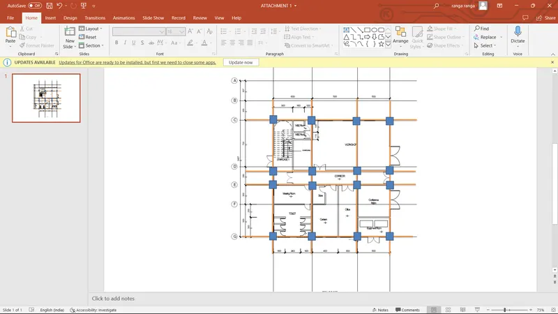
3. With reference to the input drawing as per Attachment 1, 1.1, and 1.2 and study the steel building plan and summarize your understanding of the plan. Based on your study assume and explain the location of columns and beam and develop a hand sketch for each plan
AIM :
To study the steel building plan and summarize your understanding of the plan. Based on your study assume and explain the location of columns and beam and develop a hand sketch for each plan
INTRODUCTION :
Tekla Structural Designer is an integrated model-based 3D tool for analysis and design (of both concrete and steel members) in multi-material structures.
Features include interactive modeling, automated structural analysis and design, drawing, and report creation.
Multiple design codes are supported:
-
ACI/AISC
-
Eurocodes
-
British Standards
-
Indian Standards
-
Australian Standards
The aim is to allow you to rapidly build your model, apply loads, and design the model for an appropriate set of design forces.
On a day to day basis, you do not need to be involved with the underlying analysis models to achieve this. Instead, you can focus on the design results.
To make this possible, Tekla Structural Designer automatically creates and analyzes multiple solver models, each one being based on a different but widely accepted approach.
By designing for the forces from all the solver models, you can be confident that each scenario has been catered for.
PROCEDURE :
- In here we want read the architecture plan first
- And just imagine and rough diagram of the plan
- Just draw the rough beam and column using hand or any software
- And also draw the rough diagram for given elevation diagram
RESULT :
As per the given question
With reference to the input drawing as per Attachment 1, 1.1, and 1.2 and study the steel building plan and summarize your understanding of the plan. Based on your study assume and explain the location of columns and beam and develop a hand sketch for each plan
The rough plans and models are created successfully
4. Model grid lines and construction levels as per Attachment 1. 1.1 and 1.2. All dimensions are in mm
- The base level to be 500mm below ground level.
AIM :
To Model grid lines and construction levels as per Attachment 1. 1.1 and 1.2. All dimensions are in mm
INTRODUCTION :
Tekla Structural Designer is an integrated model-based 3D tool for analysis and design (of both concrete and steel members) in multi-material structures.
Features include interactive modeling, automated structural analysis and design, drawing, and report creation.
Multiple design codes are supported:
-
ACI/AISC
-
Eurocodes
-
British Standards
-
Indian Standards
-
Australian Standards
The aim is to allow you to rapidly build your model, apply loads, and design the model for an appropriate set of design forces.
On a day to day basis, you do not need to be involved with the underlying analysis models to achieve this. Instead, you can focus on the design results.
To make this possible, Tekla Structural Designer automatically creates and analyzes multiple solver models, each one being based on a different but widely accepted approach.
By designing for the forces from all the solver models, you can be confident that each scenario has been catered for.
PROCEDURE :
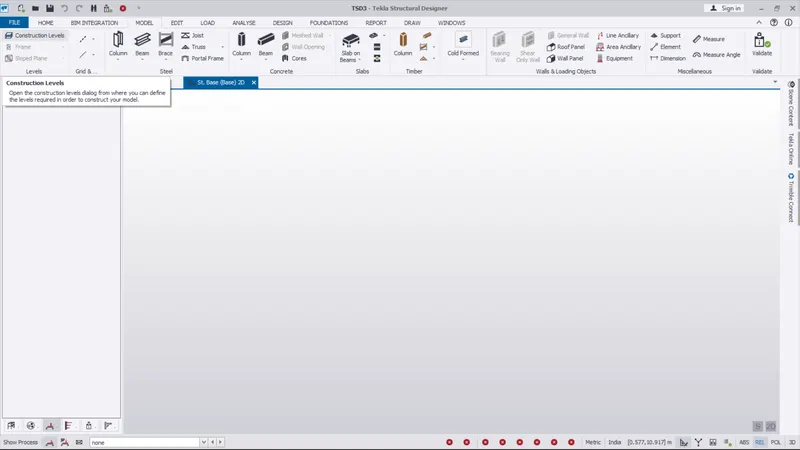
- Open the Tekla Structural Designer Software and the Software will open as follows
- Now click on new option to create a New Model Work Space
- Next we can select the model tab
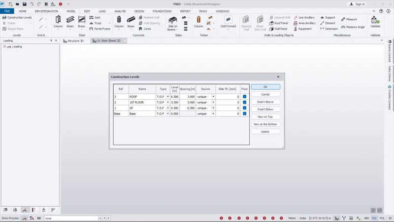
- And select the construction level
- After select the construction level the construction level dialouge box as been opend
- Use the insert above option and create floor levels
- And select the types like T.O.S, T.O.F, S.S.L
- Give the value for spacing distance
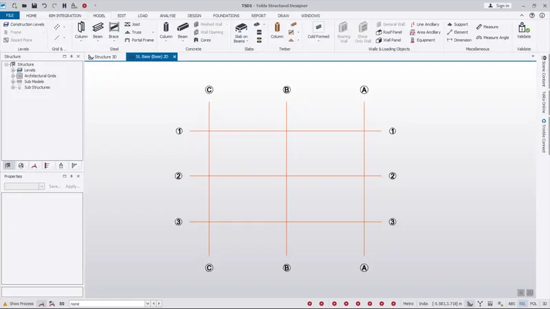
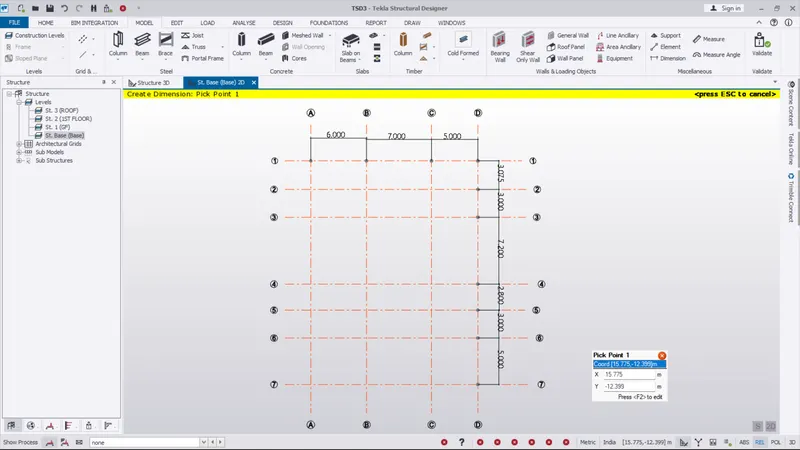
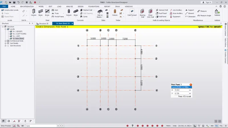
- Use the grid option to draw the grid on the screen
- And use the parallel quick and perpendicular option to draw
- After complete the grid diagram use the dimension option to draw the dimension
- finally completed the model
RESULT :
As per the given question
Model grid lines and construction levels as per Attachment 1. 1.1 and 1.2. All dimensions are in mm
- The base level to be 500mm below ground level.
The given values and models are created successfully