Creating a Layout, Section and Elevation with dimensions using AutoCad
Creating a Layout, Section and Elevation with dimensions using AutoCad
AIM :
To draft Creating a Layout, Section and Elevation with dimensions using AutoCad.
INTRODUCTION :
# LAYOUT:
- Layout is an environment within form•Z that is used for the preparation of drafted documents of projects based on sheets. In layout mode, the graphics environment is 2D and the working surface is the sheet. The drawing is created by placing views of a 3D model at specific scales and specific locations on the sheet.
# SECTION:
- A section is drawn from a vertical plane slicing through a building. This is as if you cut through a space vertically and stood directly in front looking straight at it. Sections are a common design drawing and technical architectural or engineering
# ELEVATION:
- As buildings are rarely simple rectangular shapes in plan, an elevation drawing is a first angle projection that shows all parts of the building as seen from a particular direction with the perspective flattened. Generally, elevations are produced for four directional views, for example, north, south, east, west
C0MMAND USED:
- LINE
- POLYGON
- RECTANGLE
- CIRCLE
- ELLIPSE
- ERASE
- COPY
- MIRROR
- OFFSET
- EXTEND
- ARRAY
- MOVE
- ROTATE
- SCALE
- TRIM
- CHAMFER
- FILLET
PROCEDURE :
1 . FLOOR PLAN
STEPS FOR DRAWING PLAN :
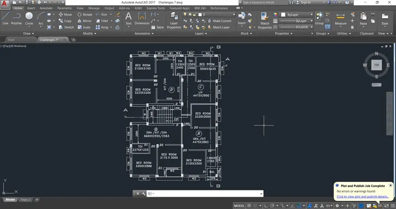
- Open a autocad and open the new files then set a units using command (UN) enter. The unit is an given by mm (MILLIMETER)
- Set the limits using limit command
- Taken the line command for draw the line, I will start the line as an down horizontally with the length of 11650mm .
- Other then taken the length of 16308 mm up of vertical direction
- Next we can taken the separate separate rooms with different dimension,and we shortly used offset command for qucik drafting of wall and room easily.
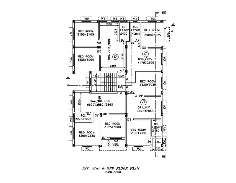
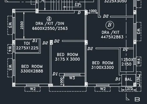
- Let we start to draw the rooms with using line command and offset command first taken the bed room as length given in the figure (3300 x 2888). and also draw the attach bath room of same bed room size of 2275 x 1225.
- Next we drawn the kitchen with the size of 6600mm x 2550mm / 2563mm
- And taken another bed room size of 3175 x 3000
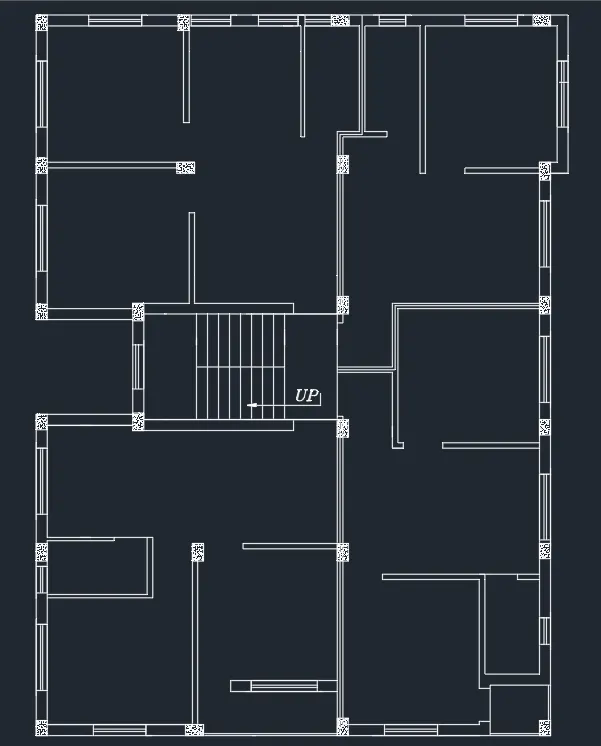
- Here we can taken the all exterior wall as 230mm, and interior wall of 115mm
- Drawn the another bed and kitchen room as right side of below the stair case as size of bed room = (3100 x 3300), kitchen = (4475 x 2863)
- Let drawn the stair case with landing of (2400 x 1200) and steps total size of 2000mm
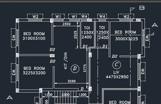
- Next drawn the upper of the staircase they have the 3 bed rooms and then 2 haves a bathroom, one kitchen, living room, size of the living room is an (4475 x 2950).
- Near or opposite side of stair case is haven a one bed room size of (3225 x 3050)mm
- Here the drawing showen the four types of windows like as w1, w2, w3, w4.
- And then the same like as the door as also shown by different types likes d, d1, d2.
- Use the trim command (tr) enter for trim the unwanted lines, and extend the wanted lines.
- And use the text command for use and write the text and dimension what we want.
RESULT :
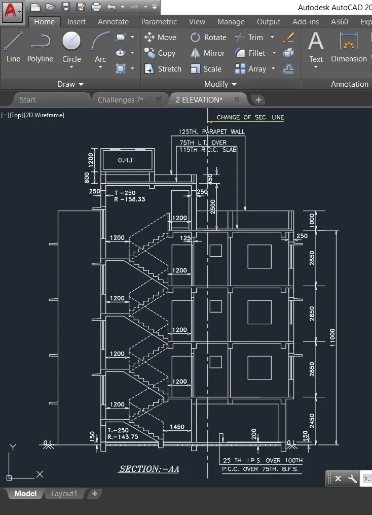
2 . SECTION AA :
STEPS FOR DRAWING PLAN :
-
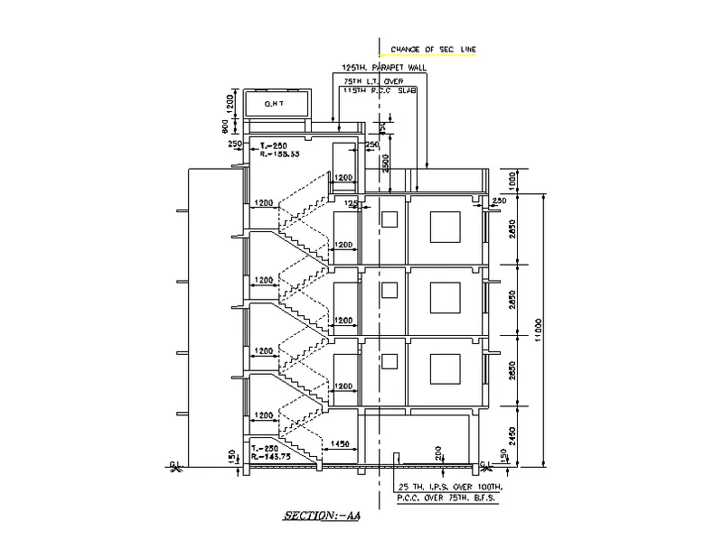
Draw the line with using line command with length of 2450, 2850, 2850, 2850, 1000 vertically forward
-
Next we have to draw another line from the previous line with the length of 150 mm wall.
-
Next again draw the line from the previous line with the length of 1100Omm horizontally backwards from the previously drawn line.
-
Use the offset command for offset the lines as value of given above
-
The inner wall offsets are 125mm and outer wall thickness is 250mm. And ground level thickness is 200mm and 150mm.Here the
-
drawing showen the four types of windows like as w1, w2, w3, w4.
-
And then the same like as the door as also shown by different types likes d, d1, d2.
-
Here next we have to draw And take the line type as dashed lines and set it to the particular value of the dashed lines for the staircase the stairs with tread of 250mm and the riser with 143.75mm and 158.33mm.
-
we required to draw the parapet wall, ground floor, first floor, second floor,
-
draw the sunshades in their particular places.
-
we can use the hatch to draw below the pcc work over the 75th. bfs
-
and can divided the section plan using different line it can be loaded in linetypes setting and open the text formate for using text the wanted dimension.
RESULT :
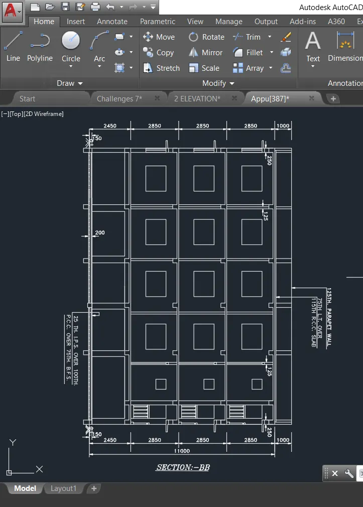
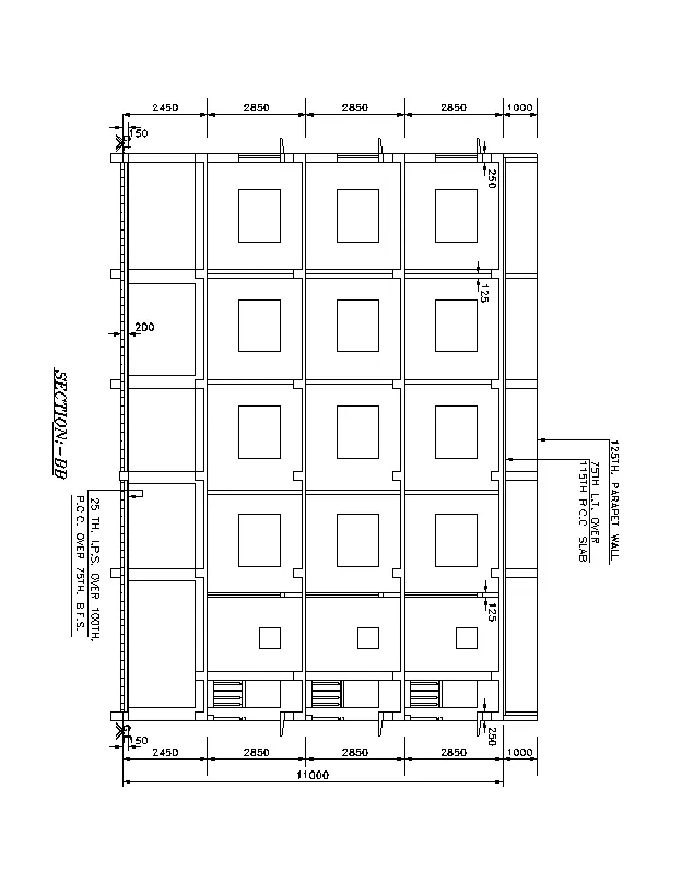
3 . SECTION BB :
STEPS FOR DRAWING PLAN :
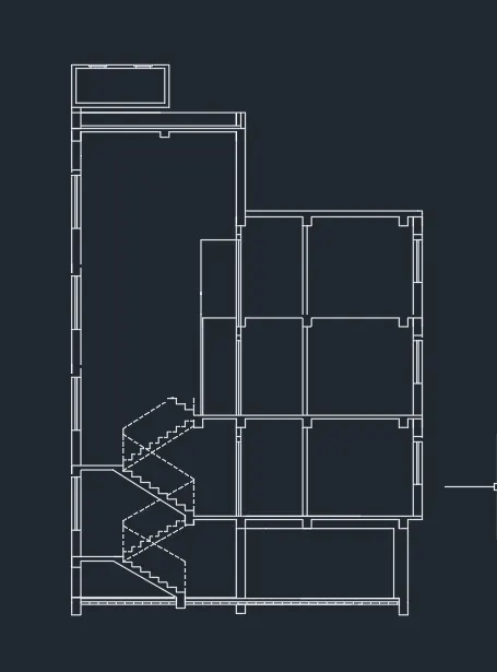
- The same like as here also used the line command for draw the line and also we can used here rectangale command for draw
- draw the line at horizontally at the size of 12000
- Project the walls and columns from the plan using LINE command.
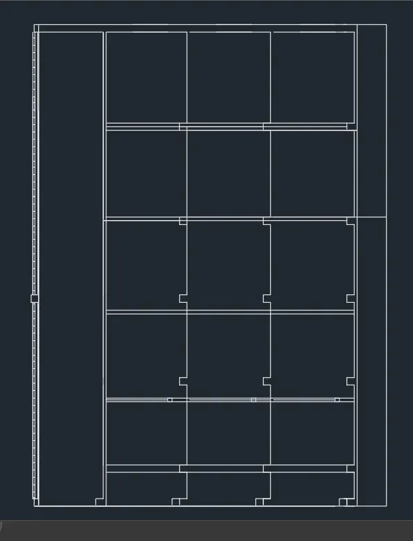
- use the OFFSET command for offset of 150mm for PCC and 200mm from the ground level is made.
- draw the rectangle and copy it easly for using command co enter
- Now offset slab of 100mm thickness and draw the beams.
- They can be shown the cutting of section in the plan
RESULT :