Project 2_Creating a 3D rendered model for a Residential Building in AutoCad
Project 2_Creating a 3D rendered model for a Residential Building in AutoCad
AIM :
To Creating a 3D rendered model for a Residential Building in AutoCad.
INTRODUCTION :
- 3D (3 dimensional) modeling basically refers to the process of developing the mathematical representation of any surface of an object in three dimensions using specialized software. ... The process of displaying the 3D model as a two-dimensional image is called 3D rendering.
- Introduction to AutoCAD 3D Commands. AutoCAD is three-dimensional CAD software that is used commercially across the world. Developed by Autodesk in the year 1982. AutoCAD is also available as a mobile and web app, which is marketed as AutoCAD 360.
COMMAND USED :
- LINE
- RECTANGLE
- 3DCIRCLE
- POLYGON
- ERASE
- COPY
- TRIM
- OFFSET
- EXTEND
- MOVE
- ROTATE
- DIMENSION
- TEXT
- FILLET
- EXTRUDE
- 3D ROTATE
- 3D ORBIT
- 3D FACE
- HIDE
- RULE SURFACE
- SURF TAB
- EDGE SURF
- REV SURF
- TAB SURF
- BOX
- POLYSOLID
- REGION
- SWEEP
- EXTRUDE
DIMENSION :
- EXTERNAL AND INTERNAL WALL - 230mm thick
- For staircase - Treads : 250 mm, Rise : 165 mm
- W - 915 x 1220 mm
- V - 406 x 1220 mm
- D1 - 915 x 2032 mm
- D2 - 915 x 2134 mm
PROCEDURE :
STEP : 1
- OPEN the auto cad file
- Set the new sheet and save as first
- We can draw the 2d plan first. so we want to set the units as in feet and inches with using engineering type in unit box as given below.
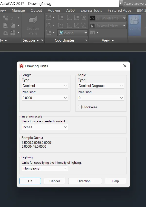
- I Set the limits with use of limit command as per size of 0,0 enter and 50,50 enter
- And type a zoom enter and all enter for fit the page
- Next using the line command to draw the line
- And also we can use the rectangle command for draw the plan as per size of 30' x 30'
- Uses offset command to offset the line as 9" inch
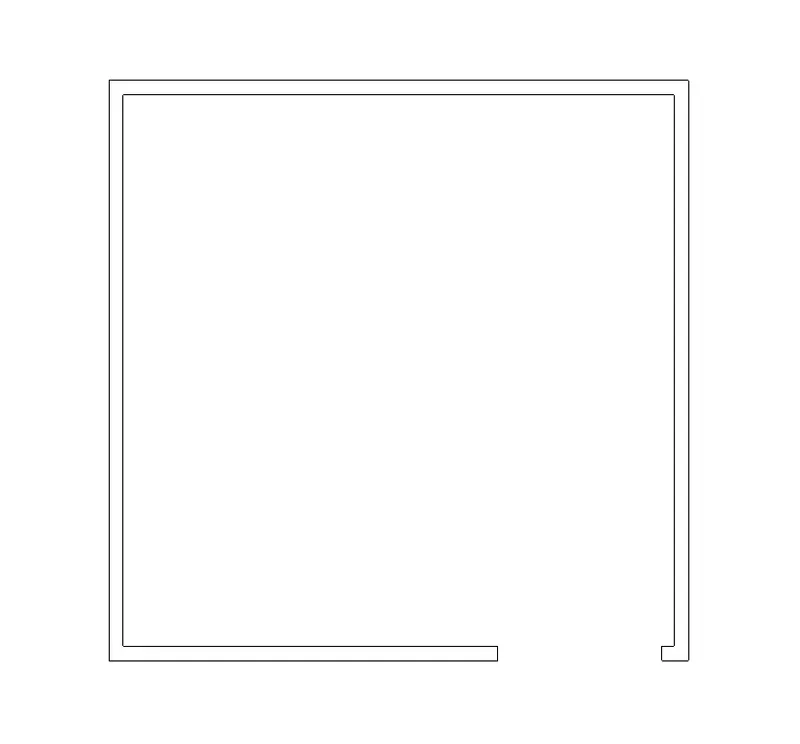
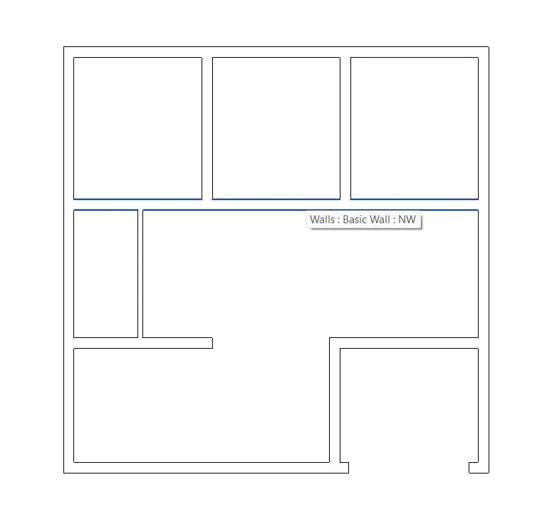
- use the line command or L enter to draw the interior room line
- At the same offset the inner line as 9" offset for normal wall and 4.5" for partition wall
- The partition wall was placed by toilet room
- In the plan they have 3 bed rooms one open kitchen and dinning, hall ,portico
- Draw the windows and use the block command for lock the diagram or using the join command for join the window
- And also using the same command as draw the door as per the size of given above the procedure and then lock the door or join the door.
- All the door as been placed in the every room corner as gap of 5 inches
- And draw the ventilater to attach in the bathroom.
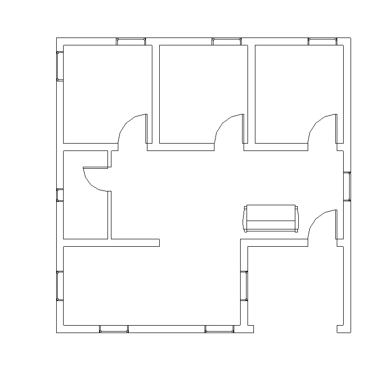
- Draw the object like bed, cook, sofa, toilet, dining table ect for fit the plan
- draw the bed as per size of 1346 x 1880 mm double slot bed
- Use the dim command for find out the dimension and also use dimlinear for marking the dimensions
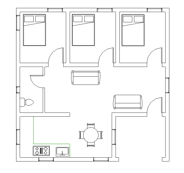
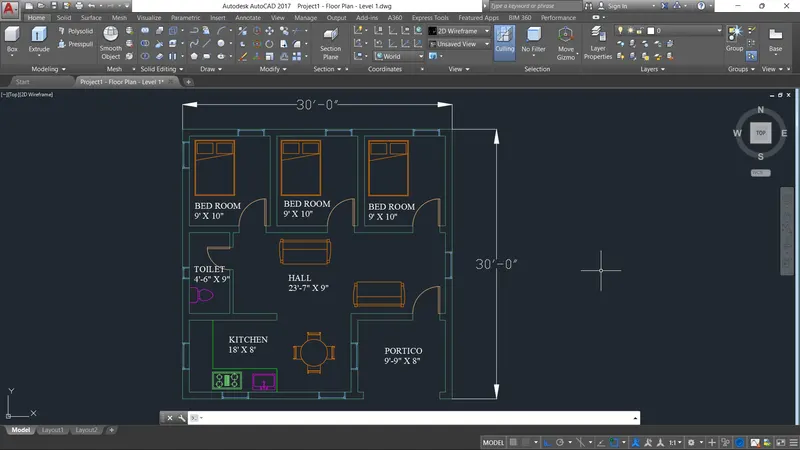
- Size of the bed room 1 = 9' x 10'
- Size of the bed room 2 = 9' x 10'
- Size of the bed room 3 = 9' x 10'
- Size of the toilet = 4' 6" x 9'
- Size of the Kitchen = 9' x 10'
- Size of the hall = 23'7" x 9'
- Size of the portico = 9'9" x 8'
- total size of building is an = 30' x 30'
- And use the text command for text the room size and dimension as for given above
--------------------------- X ------------------------------------------------- X -------------------------------
STEP : 2
- First we can change the sheet into switch = 3d modelling sheet
- Select the visual style control > 2d Wireframe
- Use the 3D orbit command to set it in proper position.
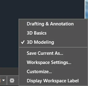
- Its the tool box were used in the 3d modeling sheet

--------------------------- X ------------------------------------------------- X -------------------------------
STEP : 3
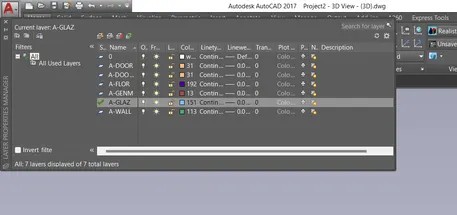
- Use the layer properties
- Click the new layer
- Given the name of the layer like 3d wall
- turn the layer > on
- make a unlock
- select layer what we want to be used
- At the same above process as followed in the all layer
- and the layers as assigned in the posistion.
- Use the extrude option maken the line to wall as height of 10' feet
- Allredy the given wall thickness as given by 9" inches
- And also use the poly solid command to draw the wall
- size of plan set by 30' x 30'
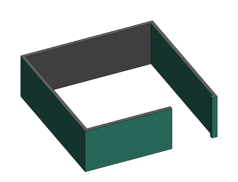
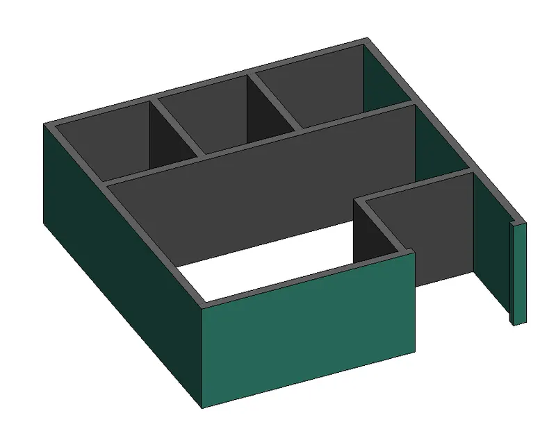
- same likes as inner wall top be finished use of extrude command
-
Provide the weist slab of 100 by using line and offset command
-
Take the boundry command and use the pick option to pick the slab 2d drawing.
-
Pick internal point
-
Select the internal portion of staircase
-
Enter
-
Visual style control> Shaded
-
Take extrude command
-
extrude command is used to maken solid up were we want to make slab thickness
Door and windows :
-
Change the layer as per requirement
-
Take the rectangle command
-
Specify first corner point > Anywhere in the drawing
-
Click> Dimension
-
Specify length of door >
- D1 - 2032 mm
- D2 - 2134 mm
-
Specify width >
- D1 - 915mm
- D2 - 915 mm
-
Take offset command to show the door frame
-
Take offset distance» 75
-
Select object > Rectangle
-
Again take offset command to show the mullion
-
Take the offset distance > 50
-
Use the region command and substraction command to make it 3D
-
Take the extrude command
-
Select object > Door frame
-
Extrude it at a distance> 100O
-
Take the extrude command
-
Select object > Mullion
-
Extrude it at a distance> 50
-
Take the extrude command
-
Select object > Door
-
Extrude it at a distance > 10
-
Use the move command to set all the components in a proper manner
-
Use the rectangle, extrude command to provide the architectural view
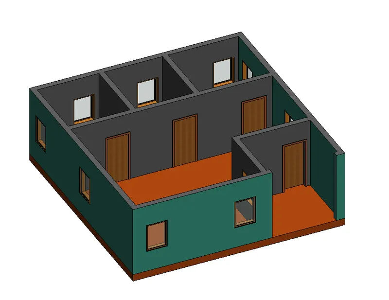
- same like as window making process as per given above.
-
Enter CO in the command line to select the Copy tool.
-
Select the window, doors, ventilator and the
-
stairs individually and copy them to their desired locations.
-
Use 3DROTATE tool to rotate the objects as required.
-
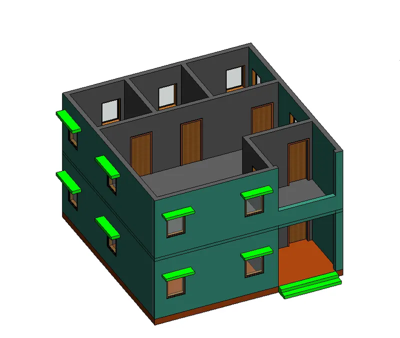
3DORBIT Command is used to control the viewing of the model when copying the doors, windows, ventilators and stairs to their respective locations.
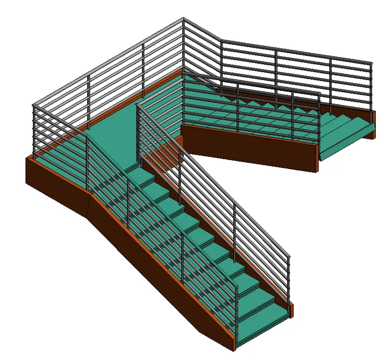
STAIR CASE :
- Set current the 3D-Stairs layer.
- Adjust the UCS to get the desired side view of the flight of stairs.
- Select the Line tool by entering 'LINE" command in the command tab.
- Draw stairs having rise of 160 and tread of 250.
- Press Esc.
- Select the Copy tool by entering 'CO' command in the command tab.
- Copy the stairs 8 times to create the flight of stairs.
- Press Esc.
- Select the Line tool by entering 'LINE command in the command tab.
- Draw the landing slab of width 750 and thickness 150.
- Press Esc.
- Select the Line tool by entering 'LINE command in the command tab.
- Draw the waist slab of thickness 150.
- Press Esc.
- Trim the unwanted portions of the line.
- Enter BOUNDARY command in the command tab.
- Specify Object type as Region and Click on Pick points icon in the Boundary Creation Dialog box.
- Click inside the stair elevation created.
- Press Enter.
- Enter EXT in the command line to select the Extrude tool.
- Select the boundary created earlier.
- Press Enter.
- Extrude it to 1000 Select the Face option.
- Select the top face of the first stair and Press Enter.
--------------------------- X ------------------------------------------------- X -------------------------------
STEP : 4
-
Go to Visualise> Render drop down list>Render Environment and Exposure.
-
Turn On Environment and make other suitable adjustments as required.
-
Next adjust the Date and Time under Sun Status.
-
Open the Render Preset Manger dialog box.
-
Select Render in> Viewport.
-
Make other chages as required.
-
Close the Dialog box.
-
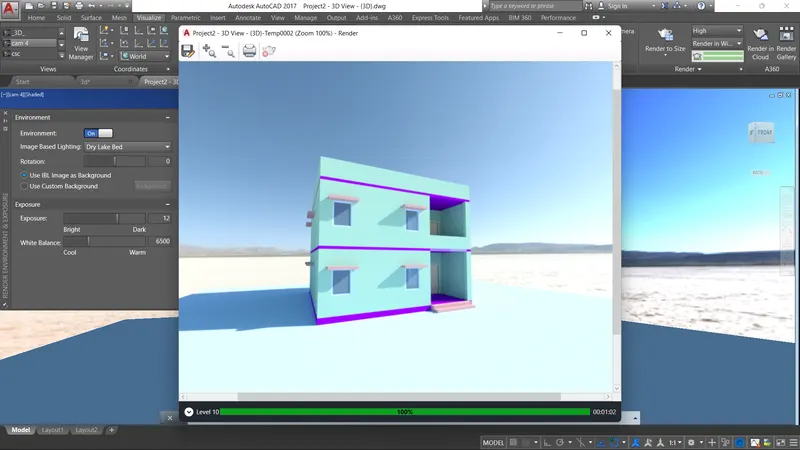
Click on the Render icon on the panel to check the camera view
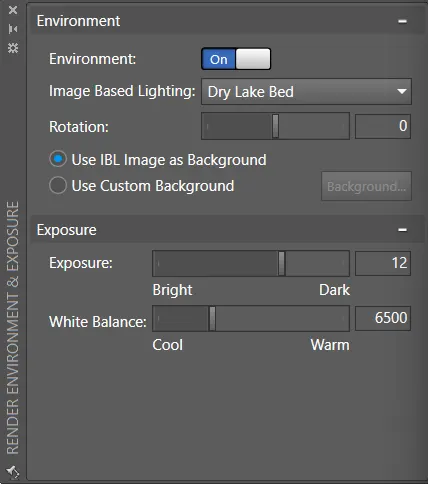
- The environment condition as making the realistic background given for the elevations
- Its taken a good look for the views
- We can select the many option make a background effect
- Here i can used the dry lake bed maken a natural green effects view.
--------------------------- X ------------------------------------------------- X -------------------------------
STEP : 5
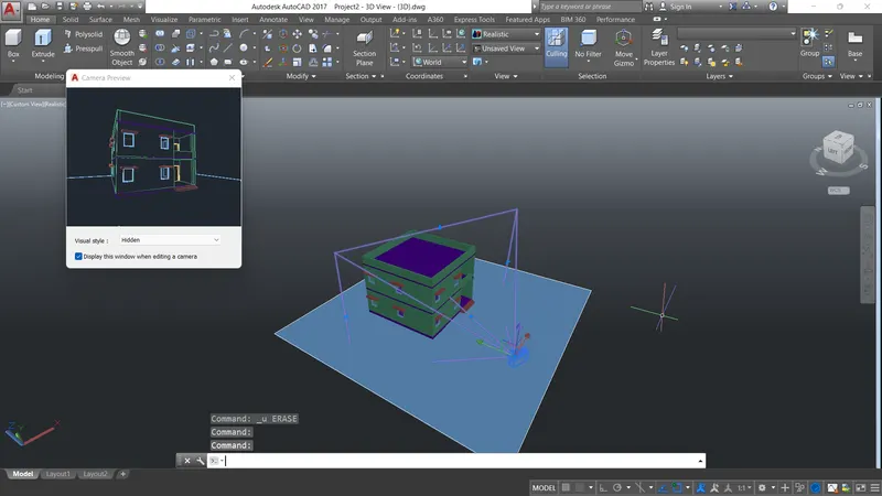
CAMERA VIEW :
- Take a circle command
- Place it at left bottom corner
- Extrude it at height > 5000
- Click> Visualise> camera
- Name it as » Cam1
-
Set target
-
Delete the cylinder
-
Click on the camera it will gives the follow result
Steps to set the Distant light :
- Take a circle command
- Place it at right bottom corner
- Extrude it at height> 20000
- Click Visualise» Create light» Distant ligh Name it as > Sun light
- Set target
- Set intensity» 100
- Delete the cylinder
- Take rr command to see the effect
- Save this image
--------------------------- X ------------------------------------------------- X -------------------------------
STEP :6
- Use the layers to set the line and extrude and can make the reality materials to apply the object for good realistic view after rendering
- After we complete the enviroment on option
- Click on the Render icon on the panel
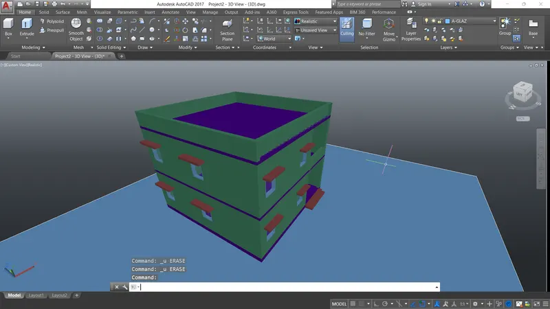
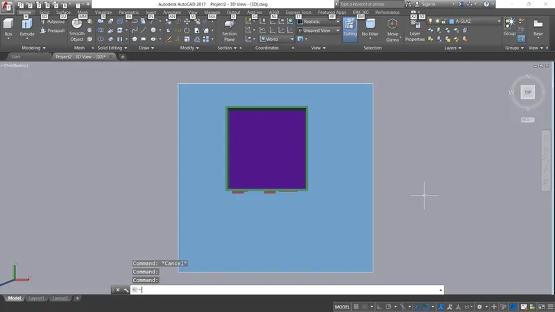
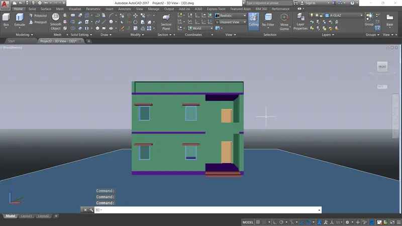
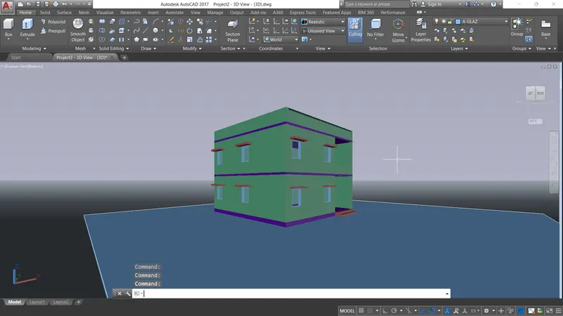
- We can render the image using with rendering option and taken the realistic view
- That the view can be shown in the below the results
--------------------------- X ------------------------------------------------- X -------------------------------
RESULT :
--------------------------- X ------------------------------------------------- X -------------------------------