Creating Architectural and Structural model with 3D rendering using REVIT
1) Select the type of structure you want to build from one of the three below:
a. Multi-Unit Residential Apartment
b. Office Buildings
c. School
RESULT :
I have choose the office building for create the structure model and architectural model
2) Assume reasonable assumptions for geographic and location details for your project modeling. Based on assumptions and type of structure selected identify the modeling requirements from NBC
Assumptions for geographic and location details for your project modeling :
- By building is constructed in the commercial area, krishnagiri (dt,tk), 635001.
- The building is constructed in the plain area (geographic).
- They are 5m three-lane road infront of my building
- As per the NBC, The height limit will be given in NBC part v-1, (National building code)
- The size of the building also as given in NBC part v-1
3) Using the structural model, include the following components based on the type of structure selected
a. Foundation – Isolated / Wall/Matt Foundation
b. Columns
c. Beams Connected to Columns
d. Roof Framing/ Truss
e. Floor / Decks
f. Floor Openings for Elevators and Stairs
AIM :
To Using the structural model, include the following components based on the type of structure selected.
INTRODUCTION :
Revit Structure is Autodesk's BIM software solution for structural engineering companies and structural engineers, that provides a feature rich tool set helping to drive efficient design processes in a BIM (Building Information Modelling) environment, or when working with other construction disciplines using Autodesk .
PROCEDURE :
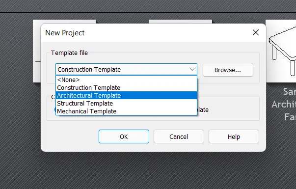
- Open the revit and select new file, they have some types to pick
- we taken the structural template to draw
- Set the units as feet and inchs
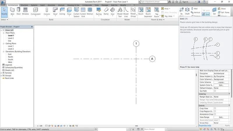
- Use the grid option in architecture tab
- Draw the grids as horizontal and vertical direction (a),(1).
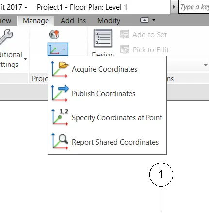
- Use the cooridinate tab in the manage option
- and pic the both grids and set as the direction values as 0'0" (enter)
- Save the diagram by using (ctrl+s) and the name as structural diagram
- Use the grids option and go to offset and the given value of 20' feet make multiple grids
- Add the foundation as with size of 1800 x 1200
- And the column size as 300 x 450mm at the junction of the grids
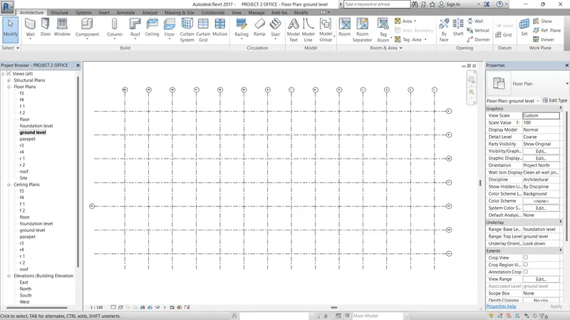
- Here we using fotting option in structural tab
- And choose the footing type we used or given above
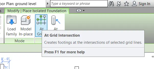
- Make the footing as all the intersection grid line
- Using the AT GRIDS option to make the footing in all intersection grids as the pitcher as given below
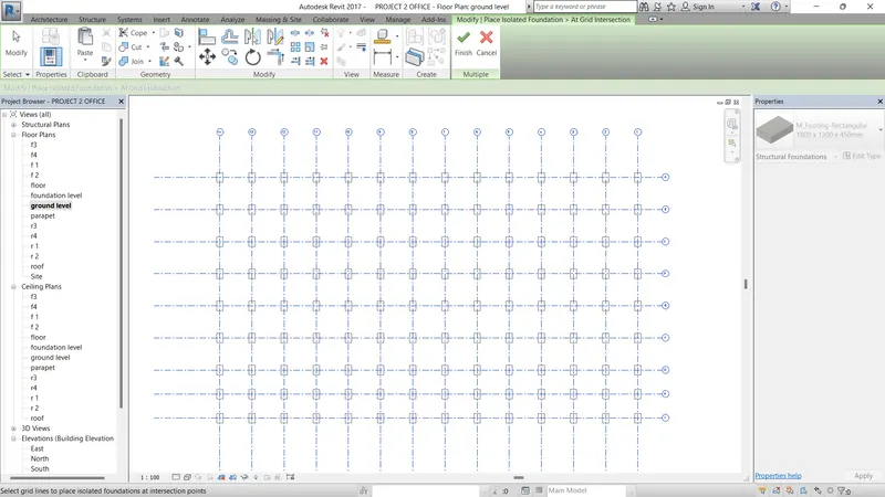
- Next we want to make the column as size of 1' x 1'6"
- Use the structural tab
- And select the column option to make column
- Go to load family and select the structural column in library
- And select the rectangle column footing after modify the size
- Use the AT GRID option to select all grid intersection posistion
- And make tick and close
- Go to 3d option and check the column and footing in 3 dimension
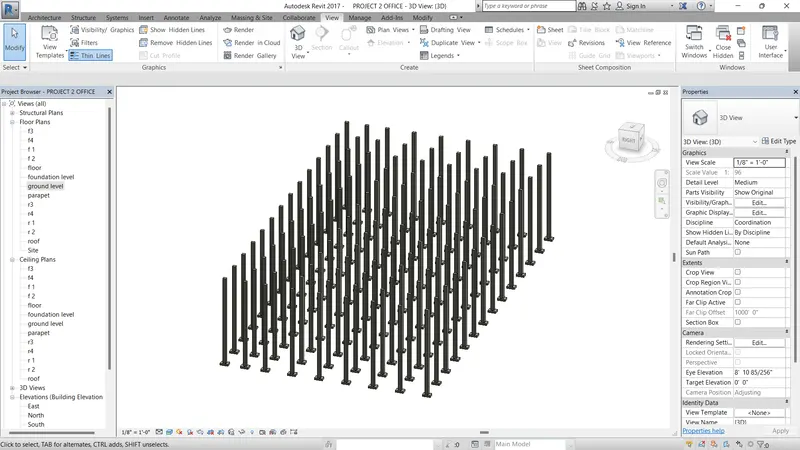
- Same like as
- Next we want to make the beam as size of 1' x 1'6"
- Use the structural tab
- And select the beam option to make beam
- Go to load family and select the structural farming in library
- And select the rectangle beam after modify the size
- Use the AT GRID option to select all grid intersection posistion
- And make tick and close
- Go to 3d option and check the beam in 3 dimension
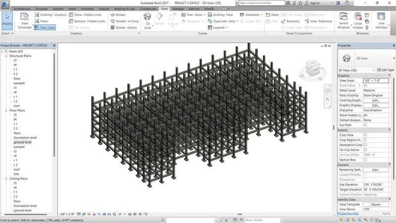
- Next we want to make the floor
- Use the structural tab
- And select the floor option to make floor
- Use the rectangle option to make the floor to draw
- And make tick and close
- Go to 3d option and check the floor in 3 dimension
- And select the floor and make the copy option and use aligned at give alligned to floor level and give give all floors
- then finally use 3d option and check slab as alligned at all floors
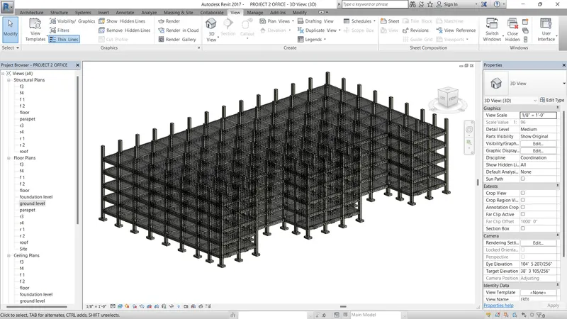
- Use the shaft option to make open the floor for uses of lift open
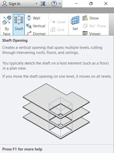
- To make to cutting the floors.
- And select the shaft option and given top offset as value of total floor height.
- And also use the shaft opening for elevator and staircase.
- place the shaft at the required position.
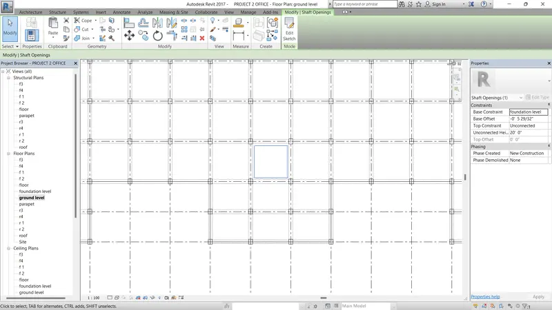
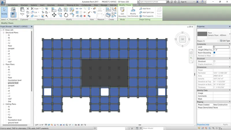
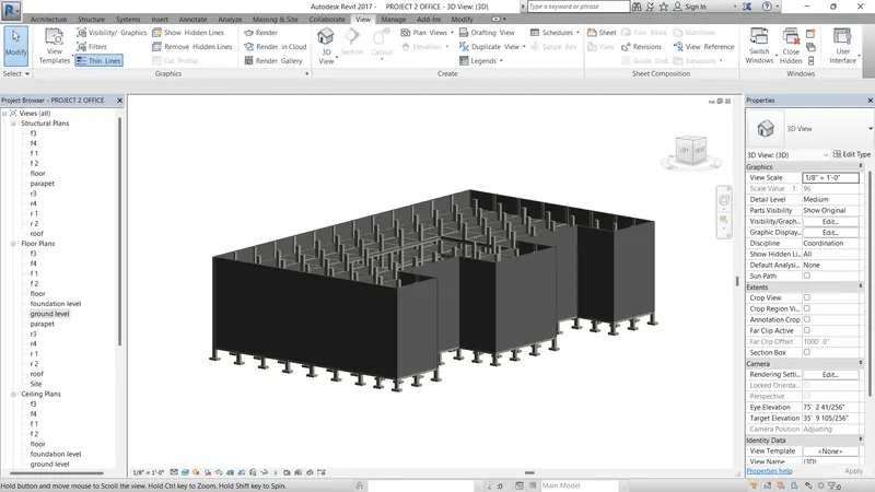
- Use the structural wall option to make the structural wall
- given the wall height in propeties option
- and give thickness of wall in edit option as same in properties option
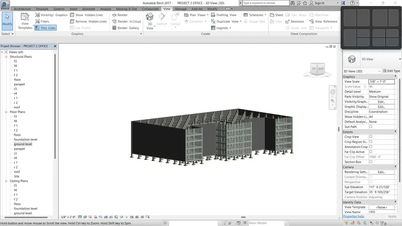
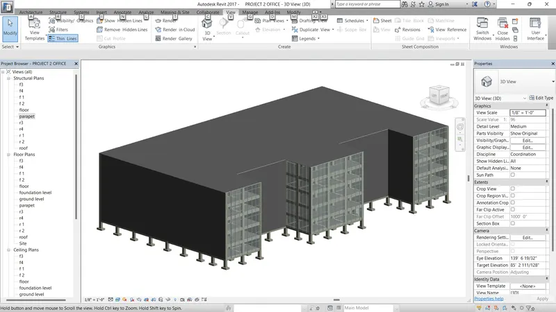
RESULT :
- The give components are sucessfully added in the structures using structural model.
4) Using the architectural model, include the following components based on the type of structure selected
a. Wall Layout with appropriate material and finishing
b. Exterior façade with fancy finish
c. Interior partition walls to size rooms
d. Components to add details to a room ( Desk, Chair, Lighting, Plumbing fixtures)
e. Add components such as stairs Elevators
f. Have at-least one side of the building with curtain walls and glass panels
g. Include interior and exterior lighting fixtures
h. Place proper topographic components from outside ( Trees, Parking, Plants) to add details to the model
AIM :
To Using the architectural model, include the following components based on the type of structure selected.
INTRODUCTION :
Components are used to model building elements that are usually delivered and installed on site, such as furniture and plumbing fixtures. Use the Type Selector to choose the desired component, or load a component family into the project. Revit provides many pre-defined components.
PROCEDURE :
- Open the revit and select new file, they have some types to pick
- we taken the Architectural template to draw
- Link the structural model to the architectural model by using the manage tab and click on the manage link.
- copy the levels and grids using the copy monitor toll.
- using the acquire coordinate tab and pick the grid and set the 0',0".
- create the levels using the command of LL
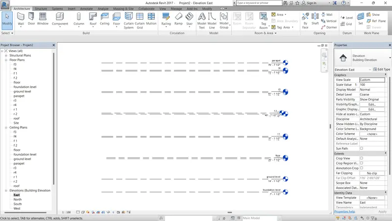
Creating floor plan :
- Click on the architectural tab walls select the wall of the thickness of 300mm
- Add the interior partition walls of the thickness of 200mm.
- click on the stair and creat the stair.
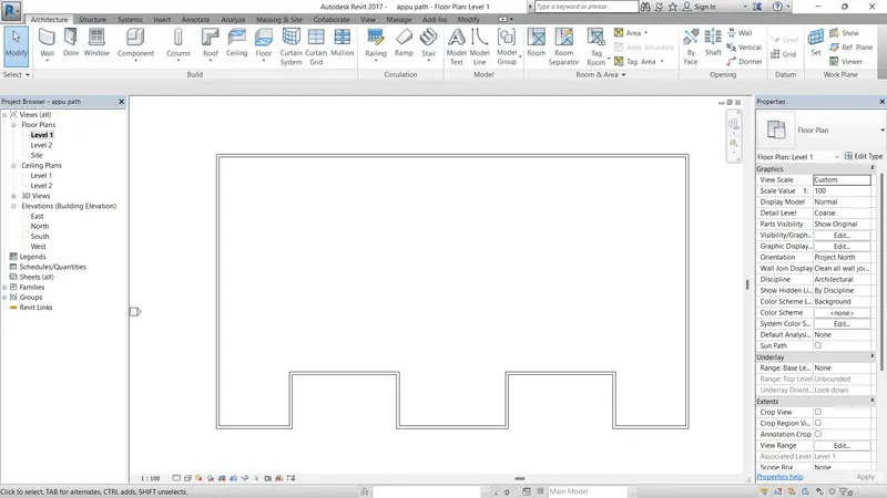
- Draw the wall on open space of slab at center
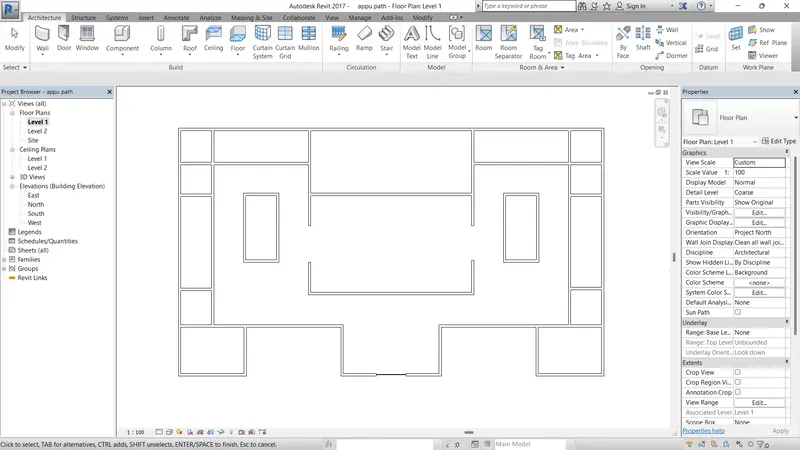
- Draw the interior wall on plan using the wall component.
- And draw the wall on interior toilet , personal assistant room, manager room, parking area, conference hall.
- And draw the stair case using of architectural tab pick a stair case option.
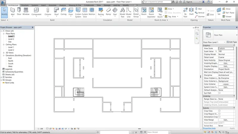
- Make door and windows using the architecture tab
- Using the architecture double door and single door. for placing on the wall
- use the same like as double and single window placing on wall
- We also modify the door and window size we want they are some standard size of door and windows.
- And also taken the alternate doors and windows on load family option.
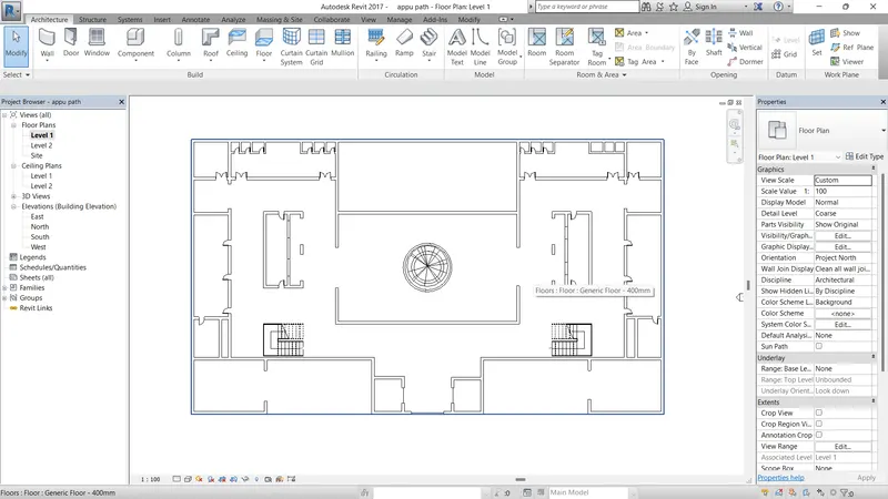
PLACING OF COMPONENTS :
- Click on the components or insert tab.
- select the load family option and load all the requirements like door, window, table, chair, sofa, car, laptop ect....,
- place all the components at the required position
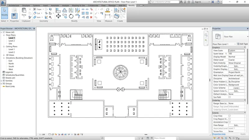
- By using the room tags place all the name of the end the dimension
- From the architectural tab select the sealing and create the celing
- use the draw or pick option to place the celeing
- And taken the light components and place at the celeing areas
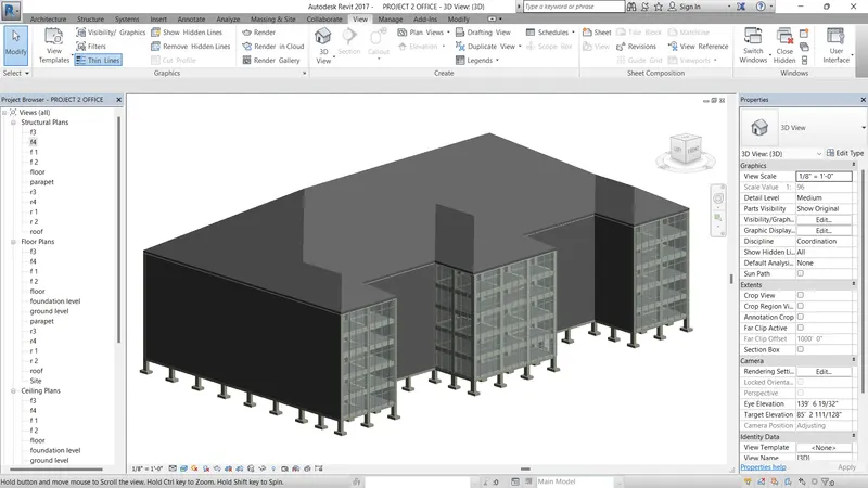
- Select all the components and then copy into the clipboard make them aligned and place into the all floors.
- Select the roof in the architectural tab and select the thickness of the roof is 400mm
- create the roof on the top by
- load the plants and exterior lighting fixture from the load family
RESULT :
- The components are sucessfully placed by the structure.
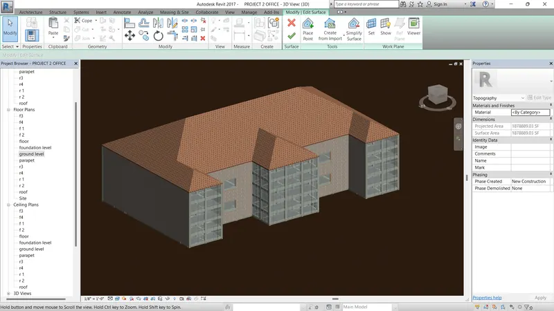
5) Provide a set of drawings in an architectural and structural model to list the following details with categories and appropriate sheet templates included
a. Floor Plans with Annotations
b. Elevations
c. Sections
AIM :
To drawings in an architectural and structural model to list the following details with categories and appropriate sheet templates included.
INTRODUCTION :
Revit is used to coordinate all data inputs (including CAD) and produce federated project deliverables. Both programs are often used within the same firm, with BIM and CAD specialists working on different elements of a project.
Create a viewport for collecting the construction documents in a set. A construction document set (also called a drawing set or a sheet set) consists of several sheets. In Revit, you create a sheet view for each sheet in the construction document set.
PROCEDURE :
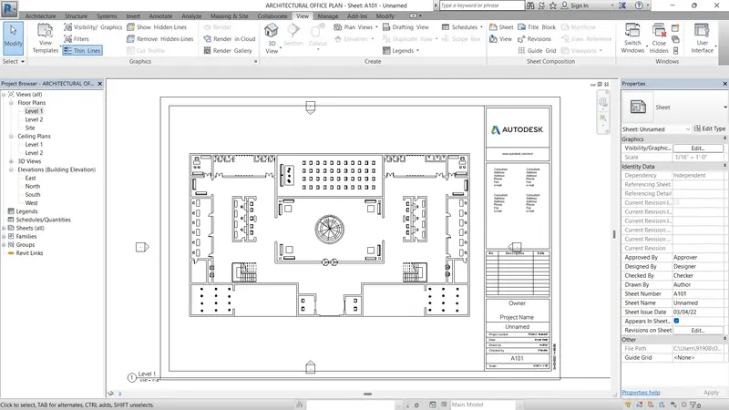
- After finishing the plans
- Select the annotation tab and select the aligned dimension to provide all the dimension.
SHEET :
- Select the view tab and select the sheet option
- And give the rename what you want
- taken the sheet size as an A2 and click ok
- After click the ok the A2 sheet as been open on the screen.
- First we want to taken the floor plan in left side of project browser.
- And make the floor plan drag and place into the sheet
- Next we set the size of floor as use of scale option on properties table
- Make change custom to othe size still set the page proper to the sheet.
SECTION :
-
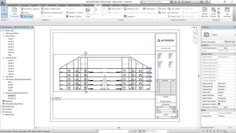
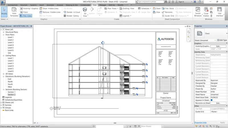
- The view tab and select the sheet option
- And give the rename what you want
- taken the sheet size as an A2 and click ok
- After click the ok the A2 sheet as been open on the screen.
- First we want to taken the section plan in left side of project browser.
- And make the floor plan drag and place into the sheet
- Next we set the size of section plan as by use of scale option on properties table
- Make change custom to othe size still set the page proper to the sheet
ELEVATION :
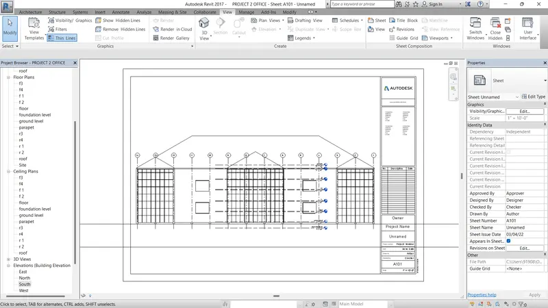
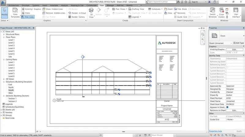
- Select the view tab and select the sheet option
- And give the rename what you want
- taken the sheet size as an A2 and click ok
- After click the ok the A2 sheet as been open on the scren.
- First we want to taken the elevation plan in left side of project browser.
- And make the floor plan drag and place into the sheet
- Next we set the size of elevation plan as use of scale option on properties table
- Make change custom to othe size still set the page proper to the sheet.
- They have four elevations like NORTH, SOUTH, EAST, WEST
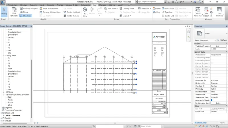
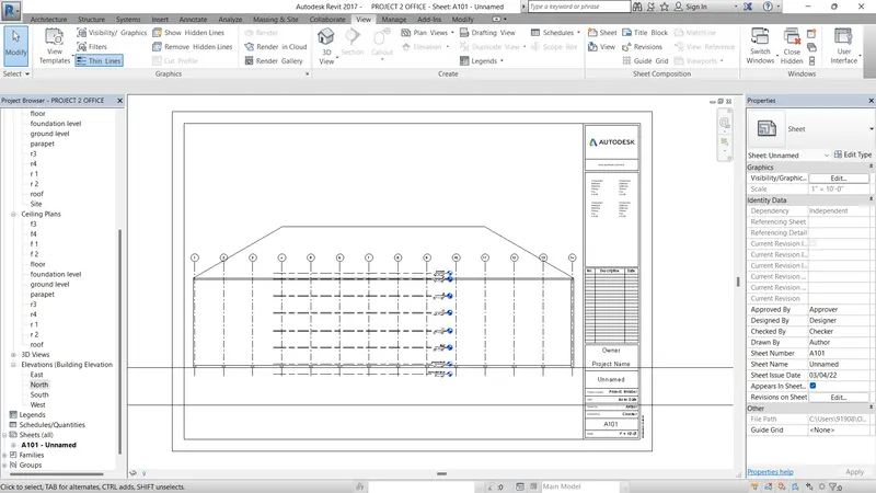
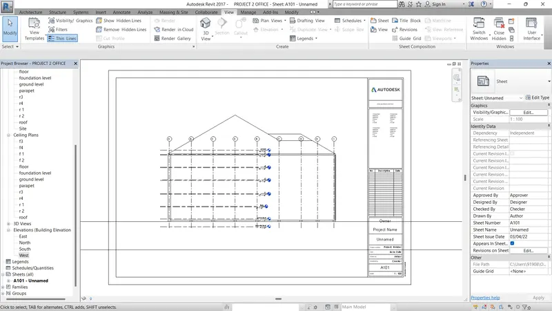
RESULT :
- Finish the making of sheet and set the floor plan, elevation plan, section plan
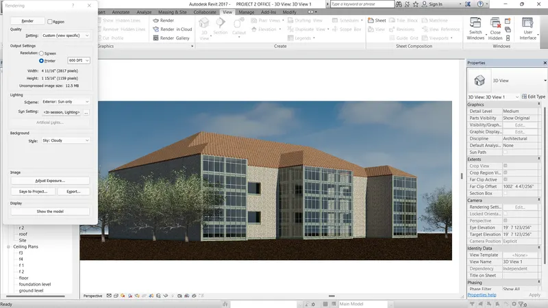
6) Using the Rendering settings, Render images of the 3D model produced and include the rendered images to the drawing sheets
a. Rendering from interior rooms
b. Rendering from out showing topographic features
c. Rendering through structural framing
AIM :
To Using the Rendering settings, Render images of the 3D model produced and include the rendered images to the drawing sheets.
INTRODUCTION :
You can render 3D views from a model. You can then place rendered images on sheets to present designs to clients. The in-product rendering interface uses intelligent defaults so that you can easily generate a quality rendered image without in-depth understanding of rendering technology.
Render the view to create a photorealistic image of the 3D model. ... After preparing the 3D view and using the Rendering dialog to select desired settings, click Render to render the image. Revit begins the rendering process, rendering the entire image progressively.
PROCEDURE :
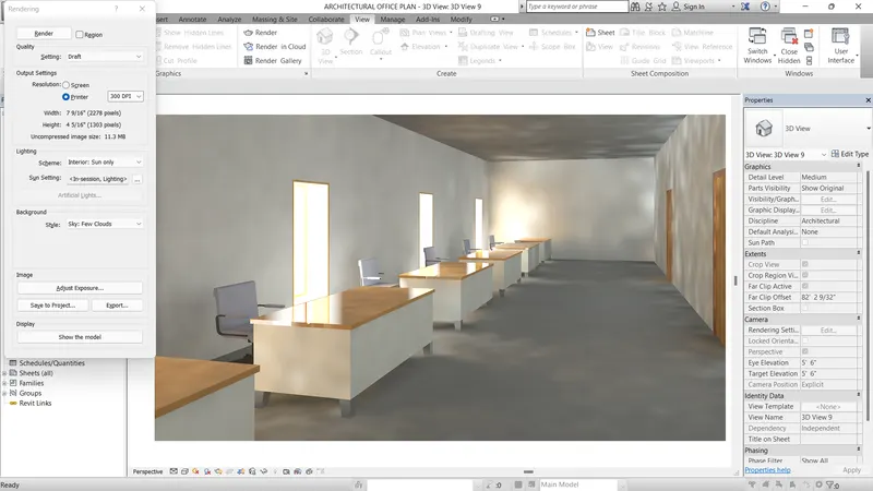
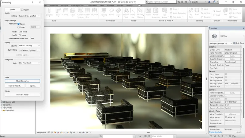
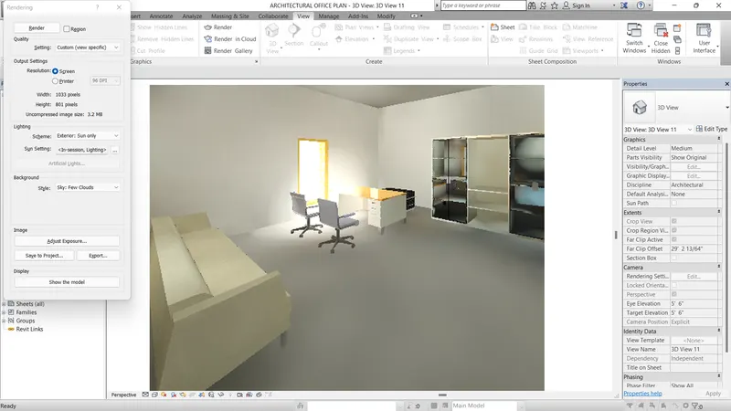
- After finishing all the structure and architecture plan at using 2d and 3d model
- we finally taken the rendering option to make the orginal shown and good quality of figure
- rendering box as given below in the picture
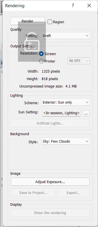
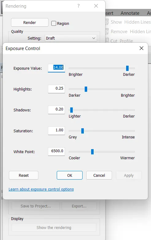
- And also the adjust of the rendering option as given below.
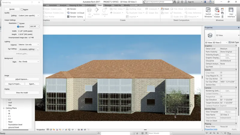
ELEVATION OF TOPOGRAPHICAL EXTERIOR VIEW :
- Use the camera option in view tab on tool bar.
- place the camera at the exterior like outer space of the area and then make the camera direction at depend on building
- After open the elevation view of building.
- Adjust the frame of the camera in elevation view
- Finally make the rendering option use of command of (RR)
- The rendering page will be open and select the custom option to make the basic good quality of rendering.
- And modify the scheme as exterior sun only
- And modify cloud quality
- Press the render button and wait for the rendering
- After finishing the rendering use the adjust explosure to modify the brightnes, colour, white point, shadow quality, saturation point.
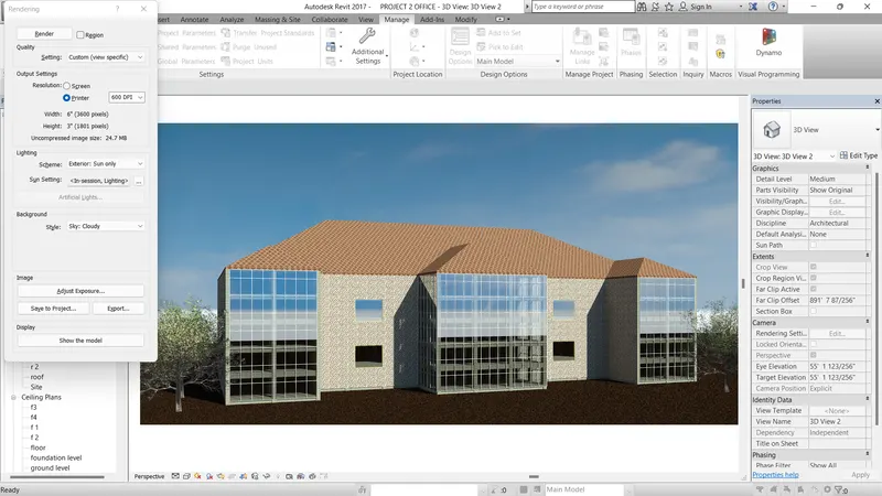
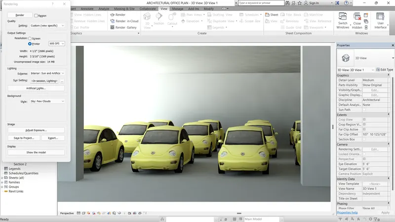
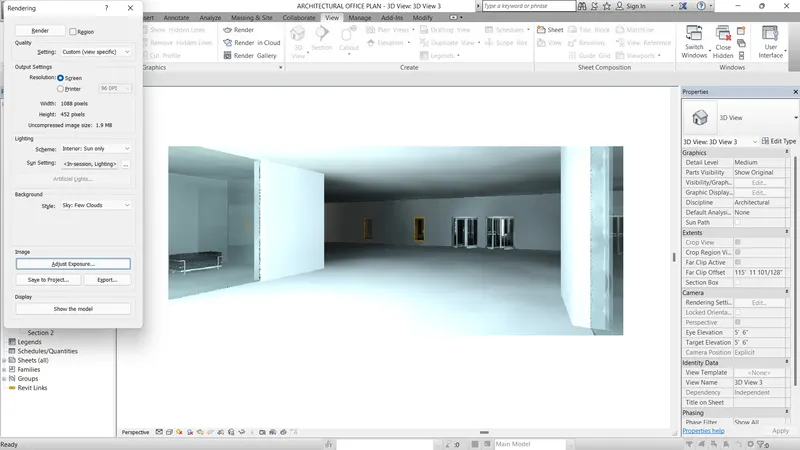
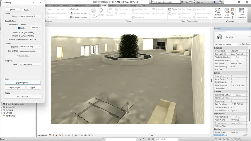
INTERIOR :
- Use the camera option in view tab on tool bar.
- place the camera at the interior room like inner space of the room and then make the camera direction at depend on components
- After open the elevation view of rooms.
- Adjust the frame of the camera in elevation view
- Finally make the rendering option use of command of (RR)
- The rendering page will be open and select the custom option to make the basic good quality of rendering.
- And modify the scheme as interior sun and light option.
- And modify cloud quality
- Press the render button and wait for the rendering
- After finishing the rendering use the adjust explosure to modify the brightnes, colour, white point, shadow quality, saturation point.
STRUCTURAL RENDERING PROCESS :
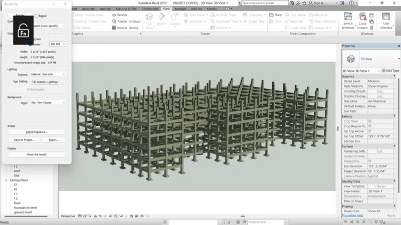
- Use the camera option in view tab on tool bar.
- place the camera at the exterior like outer space of the area and then make the camera direction at depend on structural building
- After open the elevation view of structural building.
- Adjust the frame of the camera in elevation view
- Finally make the rendering option use of command of (RR)
- The rendering page will be open and select the custom option to make the basic good quality of rendering.
- And modify the scheme as exterior sun only
- And modify cloud quality
- Press the render button and wait for the rendering
- After finishing the rendering use the adjust explosure to modify the brightnes, colour, white point, shadow quality, saturation point.
RESULT :
7) Print the set of drawing sheets created and submit the drawings from the architecture and structure model
AIM :
To Print the set of drawing sheets created and submit the drawings from the architecture and structure model
PROCEDURE :
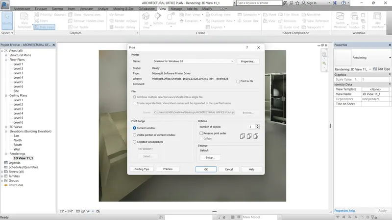
- use to print the rendering drawing as (ctrl+p) plot
- taken the plot to print
- Also we can use the pdf method for taken soft copy
RESULT :