Creating 3D Isometric view of various structural elements in AutoCAD
Creating 3D Isometric view of various structural elements in AutoCAD
AIM :
To Creating 3D Isometric view of various structural elements in AutoCAD.
INTRODUCTION :
- Isometric projection is a method for visually representing three-dimensional objects in two dimensions in technical and engineering drawings. It is an axonometric projection in which the three coordinate axes appear equally foreshortened and the angle between any two of them is 120 degrees.
COMMAND USED :
- UNITS
- LIMIT
- LINE
- DS OR OS ENTER
- REC
- UCS
- DIMLINEAR
- BOX
- REGION
- EXTRUDE
- EXPLODE
- MOVE
- COPY
- DIMSTYLE
- SUBSTRACT
PROCEDURE :
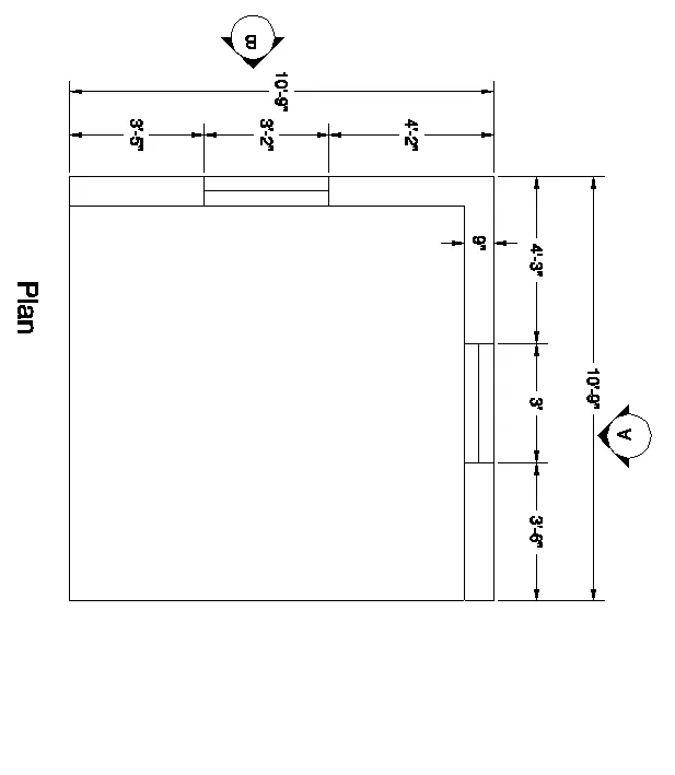
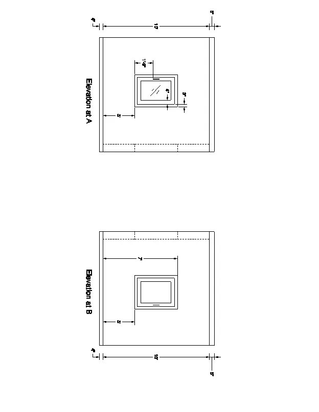
1. Create a 3D Isometric View of the building with plan and elevation given.
AIM :
To create a 3d isometric view of the given building with plan and elevation
STEP BY STEP PROCEDURE :
- First we set the units as given in figure
- As an taken the isometric view representation of 3d object
- due to the foreshoresting of the axes is equal

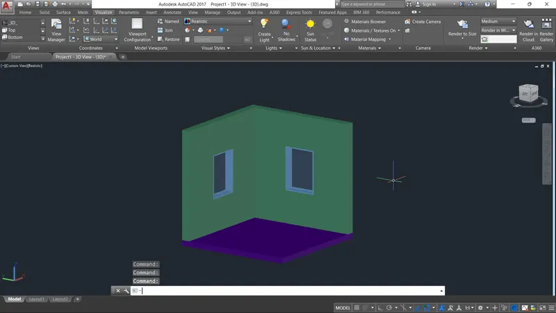
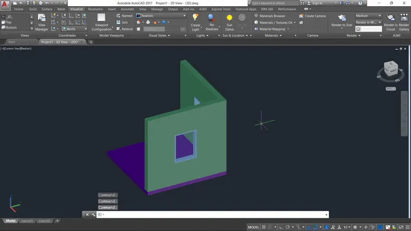
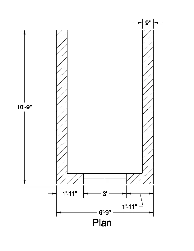
- As per given in fig the wall thickness is 9" , and they have two walls and 2 windows
- At the line of out frome this point should be constructed at an angle 30 degree
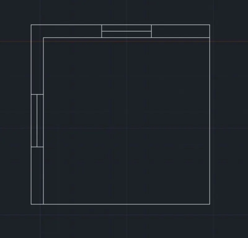
- projection of window and wall should be as an 3d modeling . and use the command of extrude to project height of 10 feet above the plan
- Leave the spacing for 2 window as the dimension given in fig
- And use the layer to colour the objects
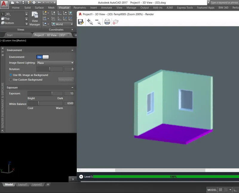
- In the visuvalisation use the render option to rendering the orginal diagram.
RESULT :
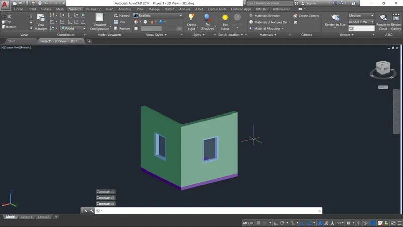
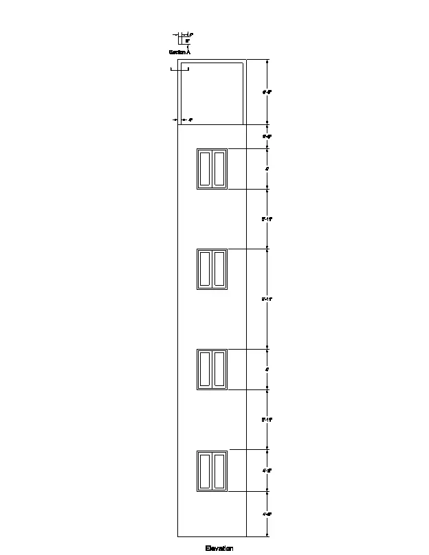
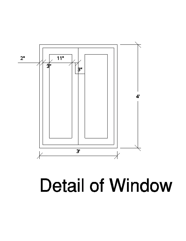
2. Create the 3D View of the Building Façade as given in the plan and elevation. Also, see the detail of the window.
AIM :
TO Create the 3D View of the Building Façade as given in the plan and elevation. Also, see the detail of the window.
STEP BY STEP PROCEDURE :
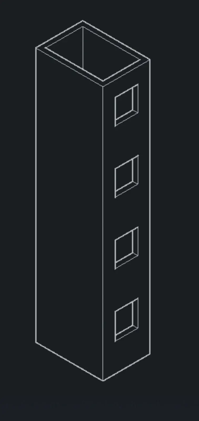
- As per the drawing is 3d representation of object as an 3d dimension of building rooms .
- use the 3d modeling sheet and tools to draw the design
- use the 3d orbit to easy view of drawing and use the extrude command to extrude the object
- use the set of ucs command as the ucs as world
- And the set view style as realistic
- extrude the total heightb of boundary is an 10'10"
- use the substract copmmand to delete the windows space on wall
- draw the rectangle command to top opening the windows
- click inside the window glass area and press enter and the all layers to give window projection
- text dimension are use the respective layers
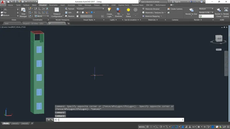
- go to the visuvalise tab and render the pitcher
RESULT :
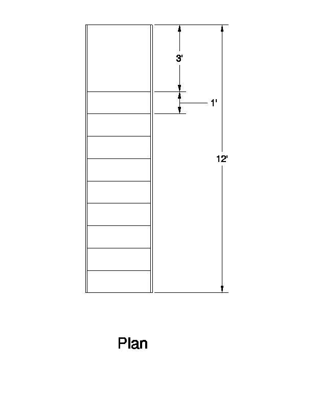
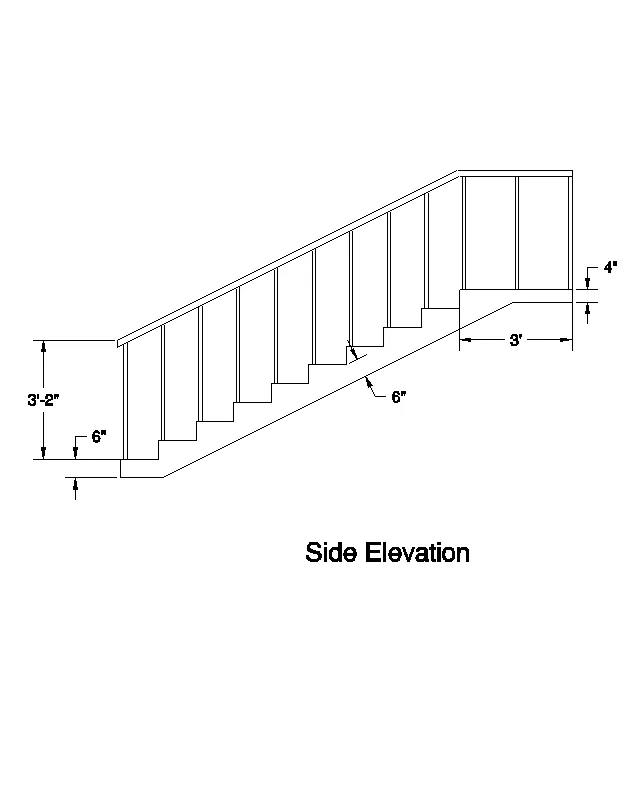
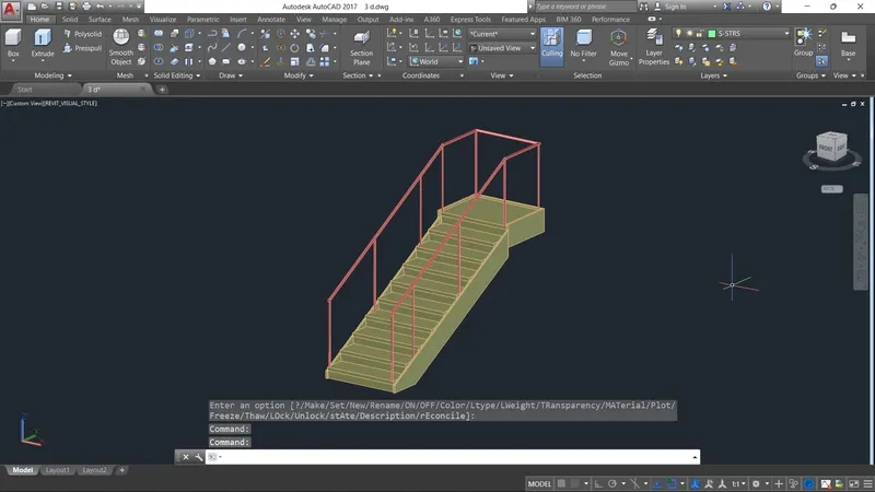
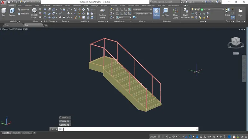
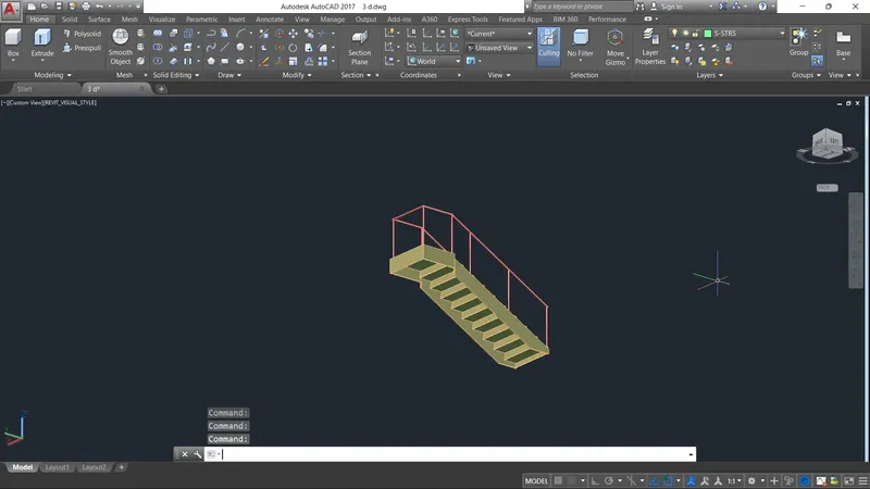
3. Create the ismoteric 3d view of a stair with railing as shown in the plan and elevation. Assume the size of the balustrades and the hand rails.
AIM :
To Create the ismoteric 3d view of a stair with railing as shown in the plan and elevation. Assume the size of the balustrades and the hand rails.
STEP BY STEP PROCEDURE :
- open auto cad and start the scratch select the impeherial to set feet and inches
- Set the unit and limits
- change the workspace as to 3d modeling sheet
- draft a rectangle as per value of 3, x 12'
- in the bottom edge we offset the object
- start the line command to draw in vertical direction
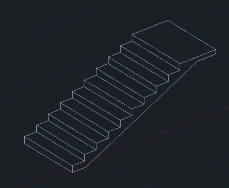
- riser height as been 6" and draw the slab joining the line
- set the ucs as world
- make a region from a view
- hand sketching the rails inn stair case
- using the copy command to make more lines and steps
- start up the sweep command to select the circle drawn
- finally render the image as uding the render option
RESULT :
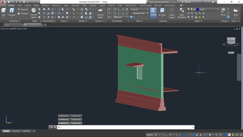
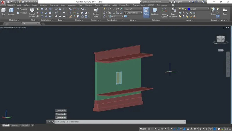
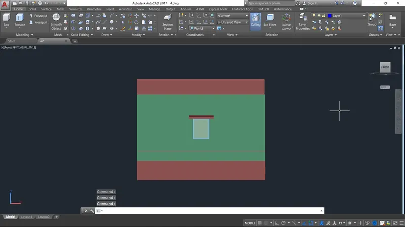
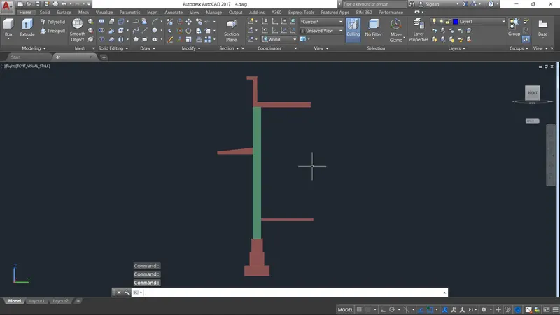
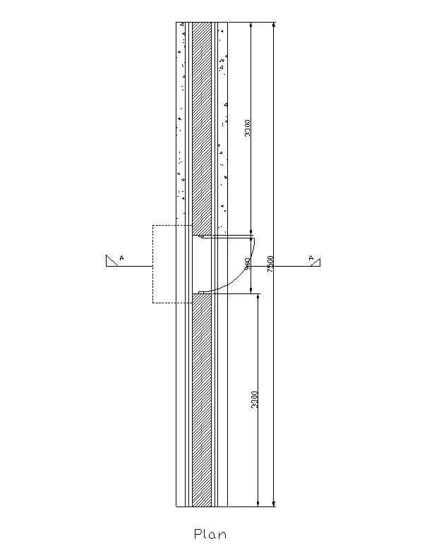
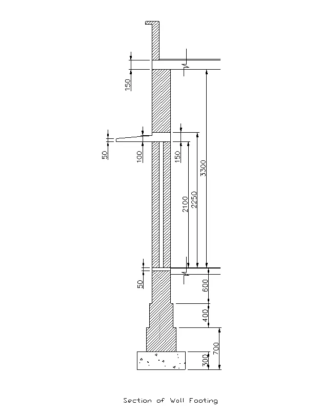
4. Create the 3D view of a Wall with spread footing . Create the Door opening only. Assume the size of the parpaet and the coping. See the plans and elevation for the details. Also, create a rendered view of the model with materials as of your choice.
AIMS :
To Create the 3D view of a Wall with spread footing . Create the Door opening only. Assume the size of the parpaet and the coping. See the plans and elevation for the details. Also, create a rendered view of the model with materials as of your choice.
STEP BY STEP PROCEDURE :
- Asusall first we set the units as mm
- open auto cad and start the scratch select the impeherial to set feet and inches
- Set the unit and limits
- change the workspace as to 3d modeling sheet
- layers are created as per follows
- taken the dimesndion of the rectangle as per 670 x 500
- extrude the rectangle as top angle
- select the individuals line and select the layers
- creating the door block as size of 50 x 100mm, and another door dimension is 50 x 50 mm
- edit the block and flip the parameters
- add the door block for rotating
- draw the roof thickness as 150 mm and the parapet wall 600 mm
- change the curent layer to footing and draw the dimension of 670 x 300
- trim the unwanted lines
- finnaly using the option of rendring to take away the orginal picture
- use the camera for rendering good view for rendering
RESULT :