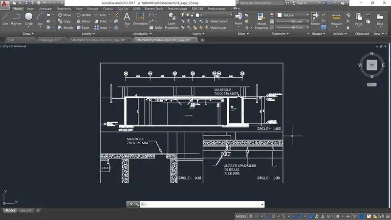
Creation of Multiple viewports, Scaling the drawing and setting in Template in AutoCad
Creation of Multiple viewports, Scaling the drawing and setting in Template in AutoCad
AIM :
TO Creation of Multiple viewports, Scaling the drawing and setting in Template in AutoCad.
INTRODUCTION :
- Viewports allow you to create different views of the objects in your model space and display them on the printed page from different angles and at different scalE.
- A drawing template file is a drawing file that has been saved with a . dwt file extension, and it specifies the styles, settings, and layouts in a drawing, including title blocks. The default drawing template files are provided as samples
COMMAND USED :
- UNIT
- LIMITS
- LINE
- RECTANGLE
- OFFSET
- TRIM
- FILLET
- ATTRIBUTE
- XREF
- BLOCK
- PLOT
- MULTIPLE VIEW
- SCALE
PROCEDURE :
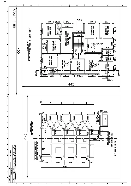
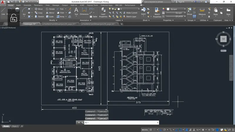
1. Create a layout of the Plan and Section A of the project in Challenges 7, using the template Tutorial-mArch.dwt in a scale as given in the Figure. Use the MV command to create the viewport of the size as shown in Figure. Also, use ATTEDIT command to edit the information in the title block. Use A1 size for the layout. Take a plot.
STEP BY STEP PROCEDURE :
- Use the line and rectangle command for draw the architextural plan as given in fig
- draw the section of the plan
- create and as size of 445 x 400 and taken a layout tab.
- Next we Select the drawings as per given figure and select it fully and now click in layout tab,to view the layout of the drawing.
- Now type MV which stands for multiple view,click it and select two horizontal from there,after this type MS which stands for model space, click it to get the desired result.
- Using the text command for making a text and dimension value as given in fig
RESULT :
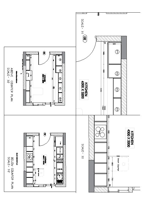
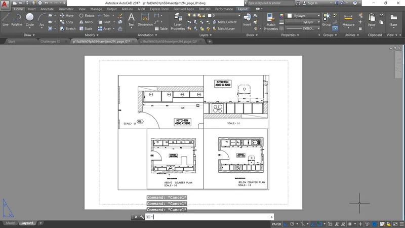
2. Create a layout of the Kitchen drawn in Challenge 9 as shown in Figure. Use the scale as shown in the Figure. Use A4 Size page for the layout. Take a plot.
STEP BY STEP PROCEDURE :
- After finishing the given diagram using the command of ps and vs to adjust the view give diagram
-
Click on layout tab,then give command VPORT ,after that select single in there and drag cursor to specify the boundary for our layout.
- command a "view" in the layout tab select the required viewport where it as be displayed and lock each all viewport.
-
Select the kitchen layouts given as per the question and select it fully and now click in layout tab, to view the layout of the drawing.now type MV which stands for multiple view,click it and select single from there,after this type MS which stands for model space, click it to get the desired result
RESULT :
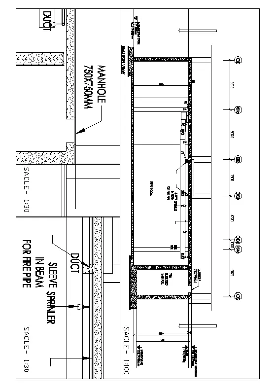
3. Create a layout of the section created in Challenges 9.
Use scale as mentioned in the Figure. Use MV command create multiple viewports. Take a plot.
STEP BY STEP PROCEDURE :
- using the command "xref" and on the left corner attach the dwf.
- if we attaching after we want left click bind the file to attach file and explode the diagram
- use mv command for create a 3 view port
- set the scale as 1:100 and tghen the text height of 6
- and fixed the diagram as in the port
-
Select the sectional view given as per the question and select it fully and now click in layout tab,to view the layout of the drawing.now type MV which stands for multiple view,click it and select SINGLE, from there, after this type MS which stands for model space, click it to get the desired result.
RESULT :