To calculate dead and live load for industrial steel structures and to apply them using TSD
1.) Calculate dead load in design report based on IS code and apply dead load on the model
- Finishes of 50mm
- Slab as per design
- Brickwall 150mm thickness
- Roofing load based on purlin size
- Ceiling loading 0f 0.3KN per sq m
AIM :
To Calculate dead load in design report based on IS code and apply dead load on the model.
INTRODUCTION :
"Dead" loads comprise the weight of the structure itself as well as things like mechanical equipment, ceiling and floor finishes, cladding, façades, and parapets. The dead load is essentially the amount of consistent weight that a building must support at all times.
The load is usually classified as either dead load or live load. Dead loads, also known as permanent or static loads, are those that remain relatively constant over time and, for example, the weight of structural elements of a building, such as beams, walls, ceilings, and structural floors. Component.
PROCEDURE :
CALCULATION OF LOADS :
- Brick wall width = 155mm
- unit weight = 20 KN/m^3
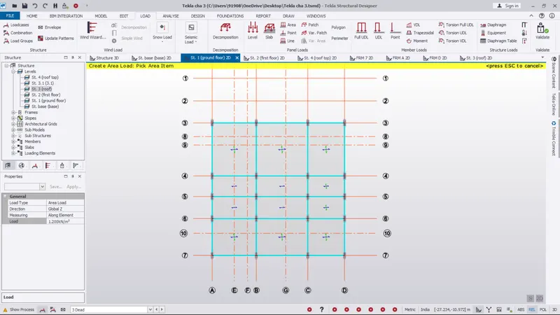
- Finishes = 50mm x 24 KN/m^3 = 0.05 x 24 = 1.2 KN/m^2
Floor height
- Floor height for (GF to FF) = 5.2 m
- Brick wall loading for ground floor = 20 x (155/1000) x 5.2 = 16.12 KN/m
- Floor height for (FF to RL) = 6.8 m
- Brick wall loading for first floor = 20 x (155/1000) x 6.8 = 21.08 KN/m
- Roofing load based on purlin size : 1.5 KN/mm^2
- Ceiling load of 0.3 KN per sq m
Step 1 :
- Open the tekla software
- Go to the new file and open
- make the new construction level and make all materials like beam, column, bracing,
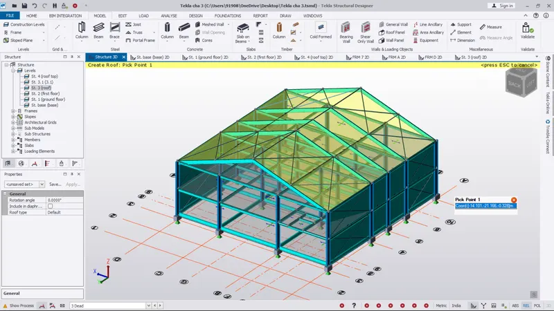
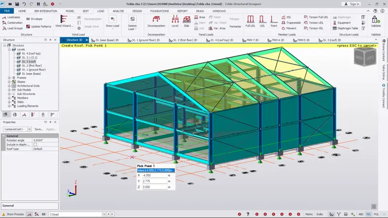
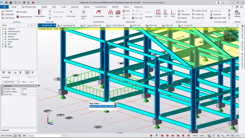
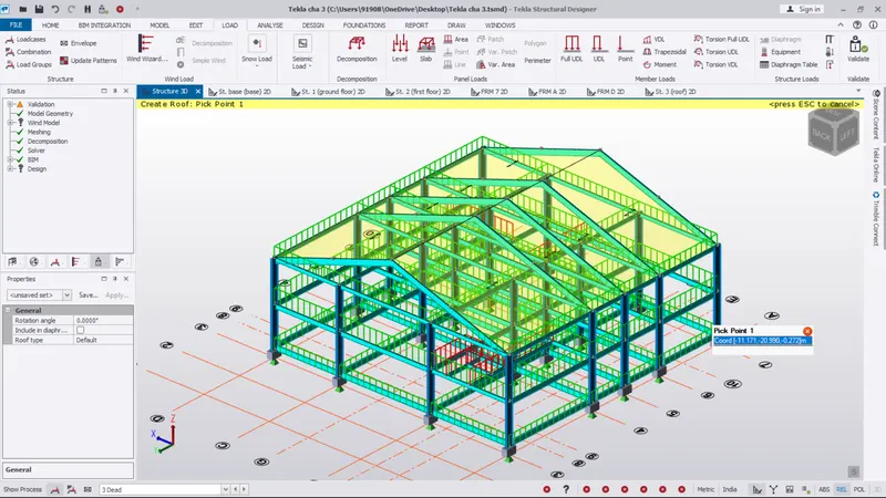
- Next go to the roof panel option
- place the roof panel on the top of the roof
- The roof panel placed image as been shown below
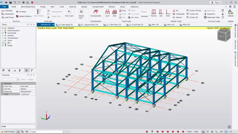
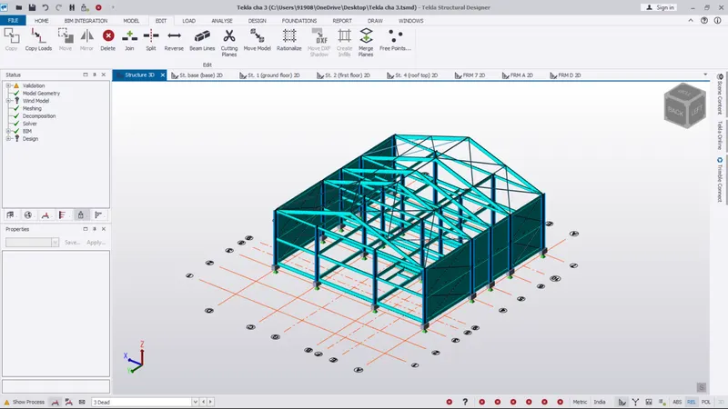
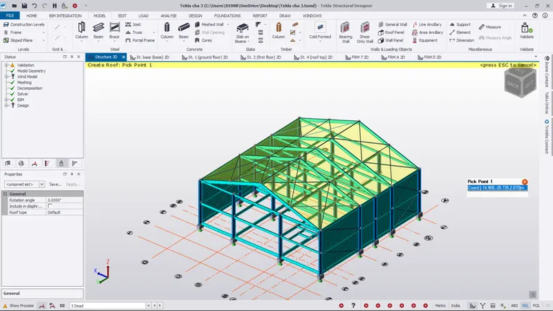
Step 2 :
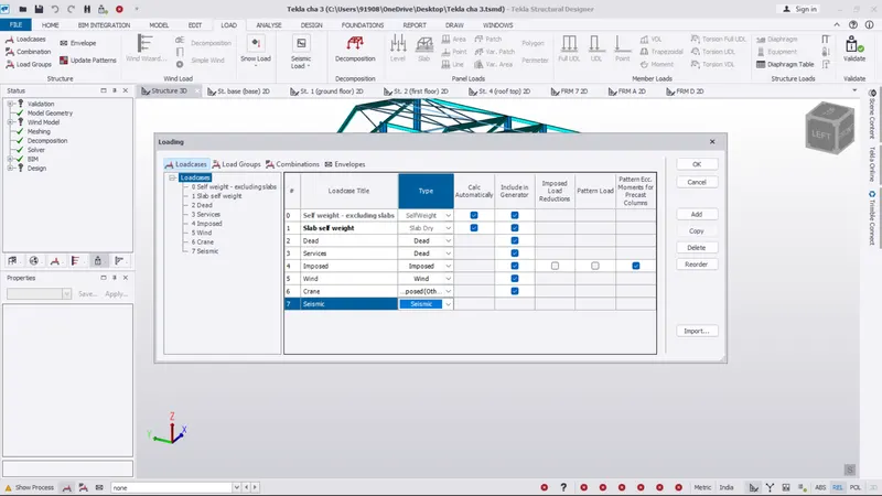
- Go to the load tab
- pick the load cases option
- The load cases dialouge box as been opened automatically
- In there create a new loads like dead, imposed, wind, crane, servises, seismic..,
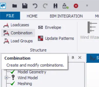
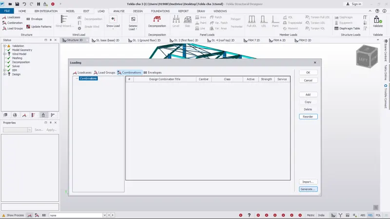
- Next go to the load combination
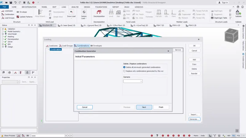
- And go to the generate option on the load combination dialouge box
- And select the 1st option and select next
- Again give the next option as 2 time
- and finally pick the finish option
- The load combination as generate sucessufully
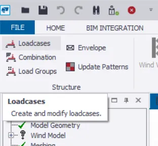
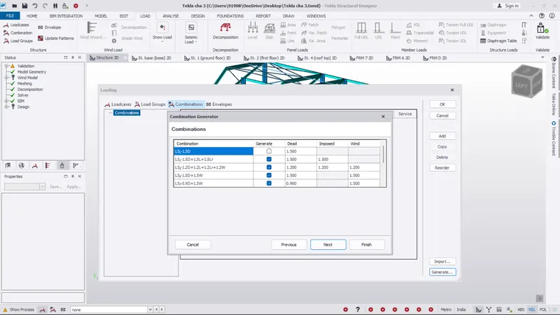
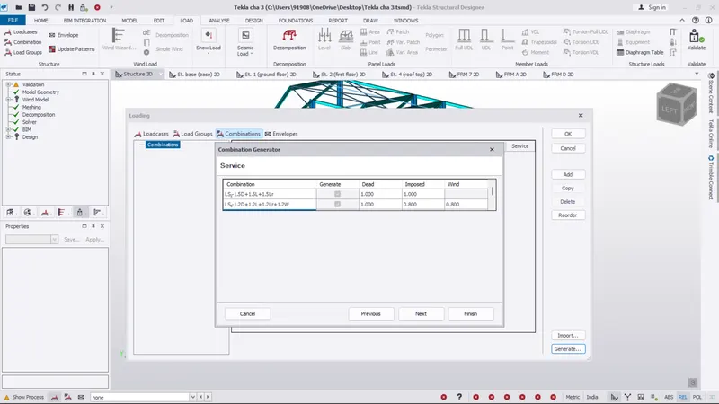
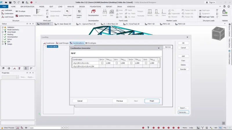
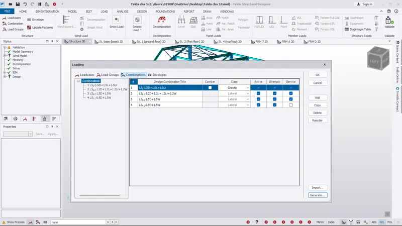
Step 3 :
- Next we want to apply the dead load
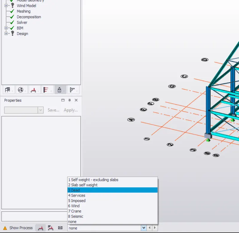
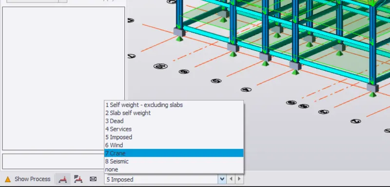
- So go to the below the screen on show process option
- And select the dead load option
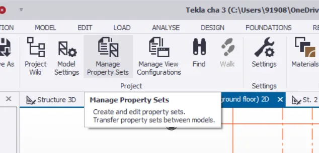
- Next go to the home tab and select the manage properties set
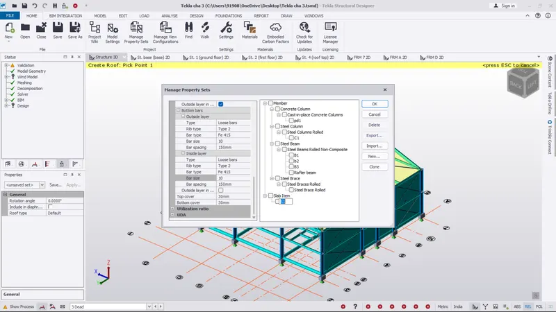
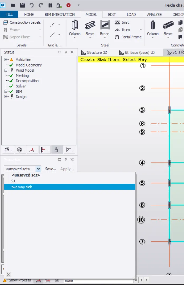
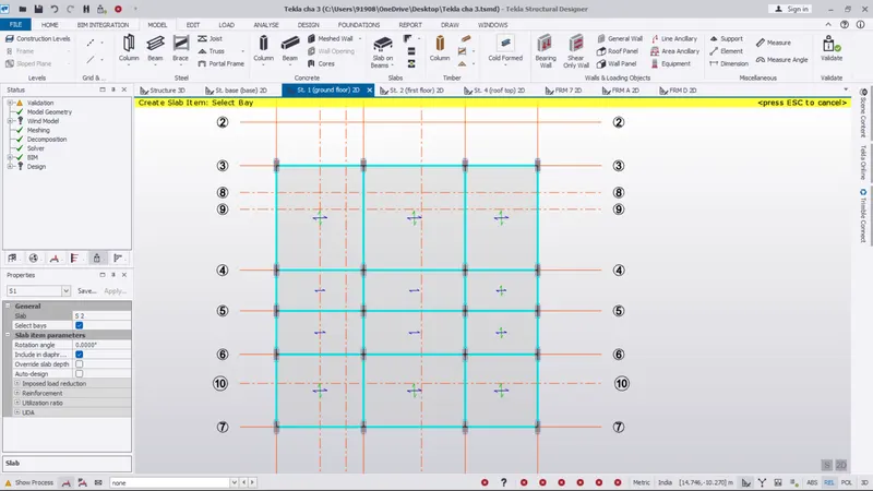
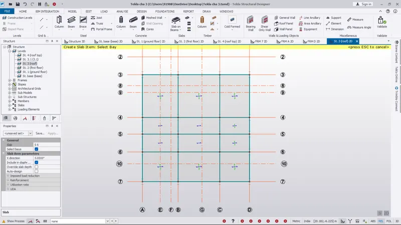
- And select the new option and select the slab items and rename it as (one way slab and two way slab)
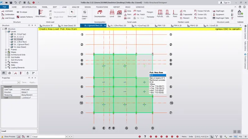
- Next go to the slab on beam option and select the slab item on general box
- As per the IS rules apply the one way slab and two way slab on the floors
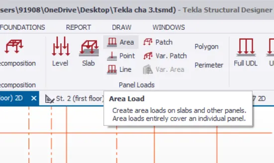
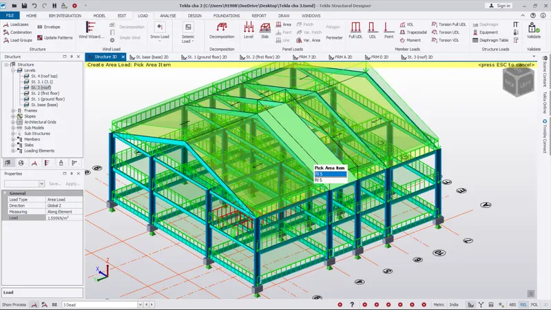
- Next go to the area load
- apply the loads on room as per same IS rules for all the floors
Step 4 :
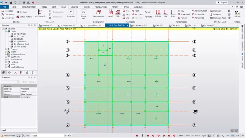
- After complete the load applyed on all the floors
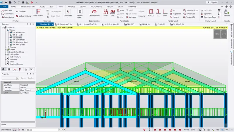
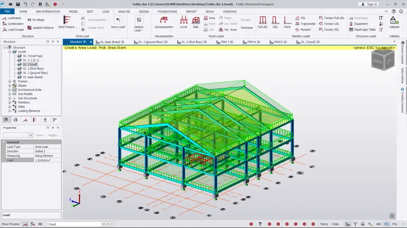
- Next apply the load on roof panel
- The load applyed image as been shown below
RESULT :
As per the question
Calculate dead load in design report based on IS code and apply dead load on the model as completed
-------------------------------------------X---------------------------------------------------X--------------------------------------------
2.) Calculate live load in design report based on IS code and apply live load on the model
- Assume the loading based on IS 875
- Roof loading
- Consider equipment loading as 5KN per sq m
AIM :
To Calculate live load in design report based on IS code and apply live load on the model.
INTRODUCTION :
Live loads are usually variable or moving loads. These can have a significant dynamic element and may involve considerations such as impact, momentum, vibration, slosh dynamics of fluids, etc.
Live load refers to occupational forces from occupancy and intended use. They represent transient forces that can be moved through the building or act on a particular structural element.
Also measured in PSF, these weights include people’s estimated weights, furniture, appliances, automobiles, movable equipment, and the like.
The load is usually classified as either dead load or live load. Dead loads, also known as permanent or static loads, are those that remain relatively constant over time and, for example, the weight of structural elements of a building, such as beams, walls, ceilings, and structural floors. Component.
PROCEDURE :
Step 1 :
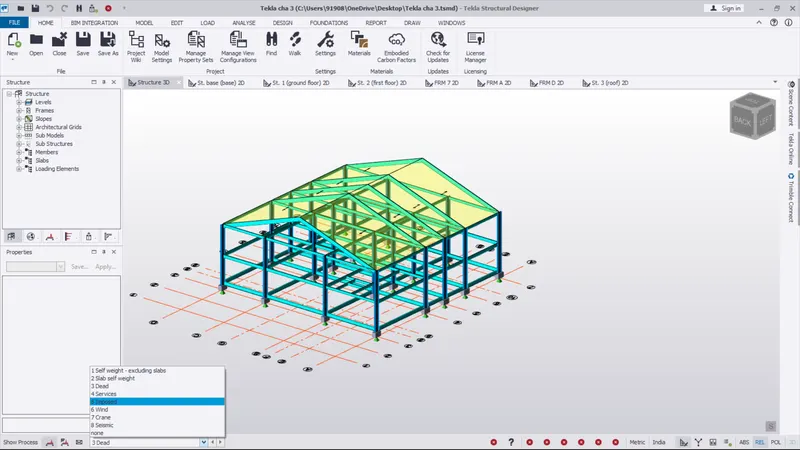
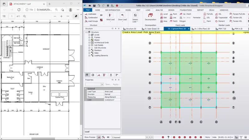
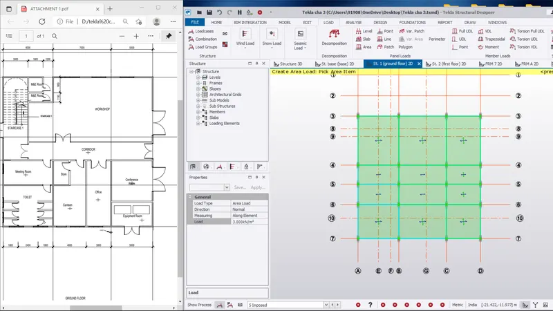
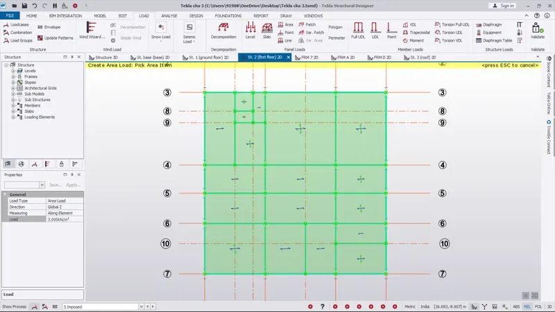
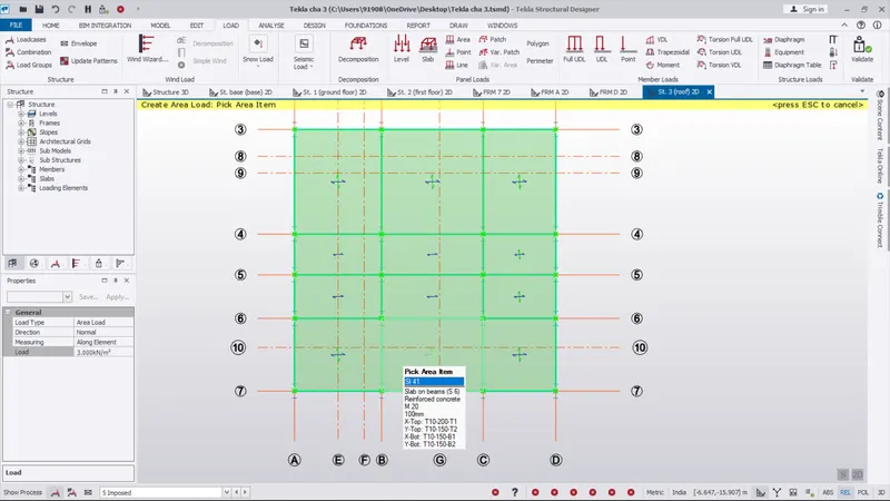
- Next we want to apply the imposed load
- AS like the same process go to below the screen "show process" set the imposed load
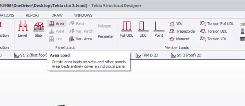
- Next go to the area load on top of the screen
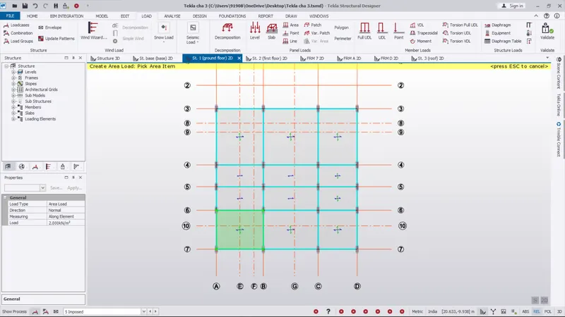
- For the all individual rooms have individula live load are there
- It as been the IS rules
- So we want to check the all the rooms live load and apply as per the IS rules
- the applyed imposed load as given in below the image
- The same process applyed all the floors
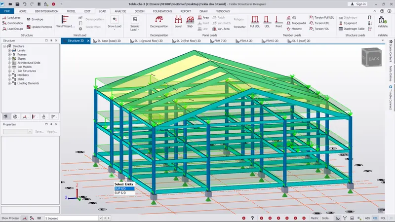
RESULT :
As per the question
Calculate live load in design report based on IS code and apply live load on the model as completed
-------------------------------------------X---------------------------------------------------X--------------------------------------------
3.) Generate a calculation for 5T crane loading based on following inputs
- Centre to Centre of wheel = 10m
- Weight of crab = 40 KN
- Number of wheels = 4
- Wheel base = 2m
AIM :
To Generate a calculation for 5T crane loading based on following inputs.
INTRODUCTION :
A crane load chart helps the operator calculate a crane's lifting capabilities. This chart ensures that the crane that is under operation does not exceed its lifting capacity. Load charts take into consideration how the lift capacity varies when considering the distance and the angle of the lift.
PROCEDURE :
Calculation of crane load :
GIVEN :
- Crane capacity= 50 KN
- Weight of crab = 40 KN
- Weight of trolley car 10 KN
- The approximate minimum approach of the crane hook to gantry girder = 1m
- Span of crane girder (c/c of wheel) = 10 m
- Span of granty girder (c/c of wheel) = 5 m
- Self-weight of rail section =30O Nm
- Yield stress of steel =250 NfmA2
- Total number of wheel = 4
- Wheelbase = 2m
SOLUTION:
1.) Maximum wheel Ioad
- Maximum concentrated load on crane = 50 + 10 = 60 KN
- Self weight of crane will act as uniformly distributed load of intensity = 40 /10 = 4 KN/m
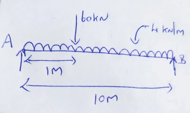
Taking Moment about B
(RA X 10) - (60 X 9) - (4 X 10 X 5) = 0
RA = 74 KN
Taking Moment about A
(RB X 10) - (60 X1) - (4 x 10 x 5) = 0
RB = 26 KN
-
RA + RB = 100 KN
The reaction of the crane gider is distributed equally on two wheel at the end of the crane girder.
Maximum wheel load on each wheel of crane (RA/2) = 74/2 = 37 KN
2.) Maximum Bending Moment:
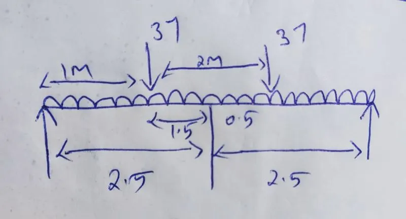
Assume self-weight of gantry girder as 1.5 KN/m
Assume self-weight of rail as 0.3 KN/m
Total dead load = 0.3 + 1.5 = 1.8 KN/m
At D :
(RC X 5) - 37 x (2.5 + 1.5) - 37 X (2.5 - 0.5) = 0
RC = 44.4 KN
At C :
(RD X 5) - 37 (0.5 + 2.5) - 37 X 1 = 0
RD = 29.6 KN
-
RC + RD = 74 KN
Bending Moment under a wheel load due to live load
RD X 2 = 29.6 X 2 = 59.2 KNm
Bending moment due to impact = 0.10 X 59.2 ( 10 % due to M.o.T)
= 5.92 KN m
Total bending moment due to live load and impact load = 59.2 + 5.92 = 65.12 KNm
Bending moment due to dead load WI^2/8 = 1.8 X (5 x 5) /8 = 5.625 KNm
Maximum bending moment = 65.12 + 5.625 = 70.745 KN m
3.) Maximum shear force:
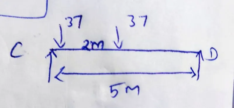
At D :
(RC X 5) - (37 x 5) - (37 x 2.5) = 0
RC = 55.5 KN
Hence the Maximum shear force due to wheel load is = 55.5 KN
Lateral Forces :
Lateral force transverse to rails = 5% of the weight of crab and weight lifted
= 0.05 x (40+10)
= 2.5 KN
Lateral forces each wheel F1 = 2.5/2 = 1.25 KN
Maximum horizontal reaction due to lateralforce by proportion at C
= Lateral force x reaction at c due tO vertical load / Maximum wheel load due to vertical load
= 1.25 x 44.4 / 37
= 1.5 KN
Horizontal reaction due to lateral force by proportion at D
2.5 - 1.5 = 1 KN
Bending moment due to lateral load = (1.25 / 37) X 55.5
= 1.875 KNm
PROCEDURE FOR TSD :
Step 1 :
- Open tekla software and
- Here we want to set the crane load
- So go to the crane load option on below the screen
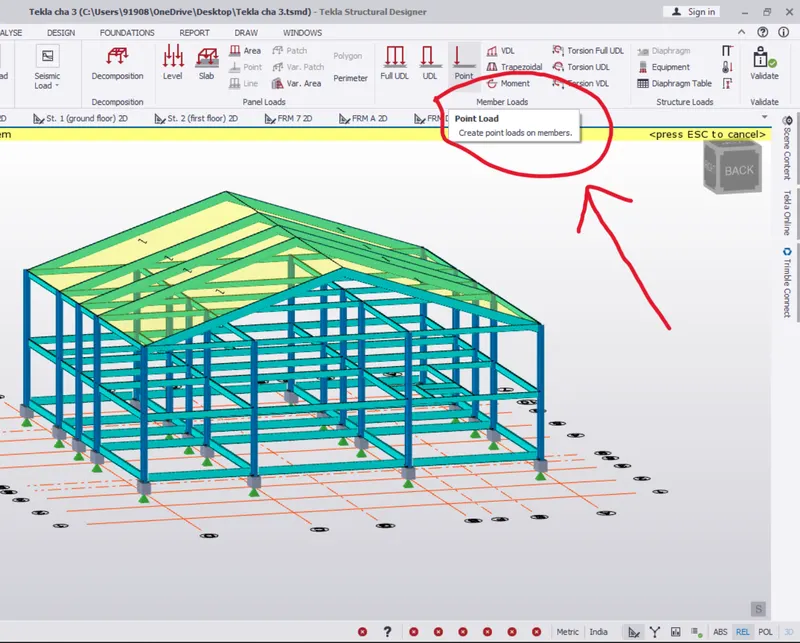
- Next go to the load tab
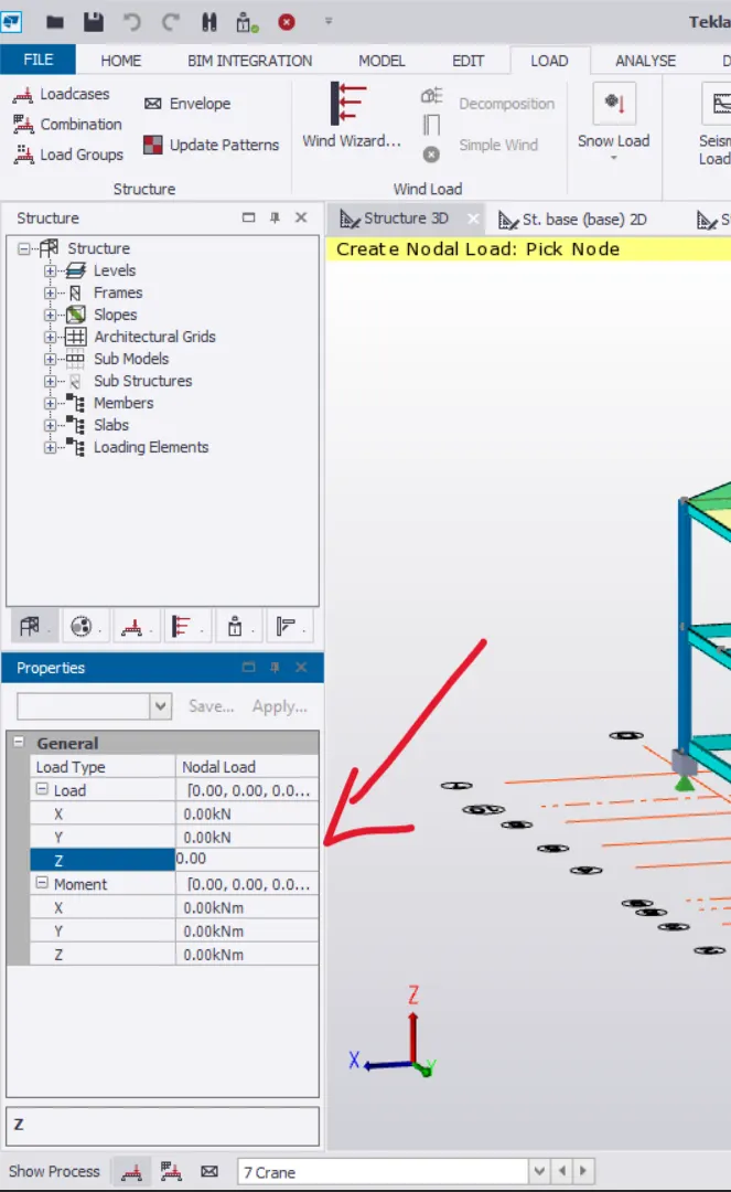
- pick the point load and go to the left side of general box
- In there set the load type as nodal
- And give the value we derived
- Next go to the crane lifing beam and apply the load
RESULT :
As per the question
Generate a calculation for 5T crane loading as derived and completed