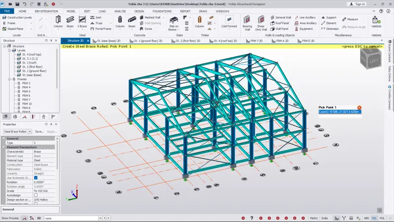
To model beams and bracings for industrial steel structures using TSD
1. Create beam properties for First floor and model the beams
AIM :
To Create beam properties for First floor and model the beams
INTRODUCTION :
Structural steel beams are iconic to modern architecture. Not only do they look great, but steel’s strength makes it a timeless and practical material. There are strict quality standards in place pertaining to steel beam shape, size, composition, and storage practices. The most common types of structural steel beams include the I-beam, L-beam, and T-beam, which come in regular, tapered, and semi-tapered. These shapes are usually achieved by hot or cold rolling but there are others that are made by welding plates, either flat or bent.
A single construction project usually uses different types of materials and different kinds of structural steel beams in order to achieve the desired result. Building materials can consist of structural steel, which is available in many different forms, as well as concrete, wood, clay, and mortar, to name a few. If the structural frame of a building will be utilized for load bearing applications, then structural steel is considered to be the most suitable material for this purpose.
The majority of industrial and commercial buildings are constructed with either structural steel beams or reinforced concrete. During the design process, it is the job of the engineer to identify which of the two (or combination of the two) will be used to achieve the best result possible. There are many things that need to be considered when deciding on what construction material will be used. Factors include availability, weight, fire resistance, strength, sustainability, and constructability.
PROCEDURE :
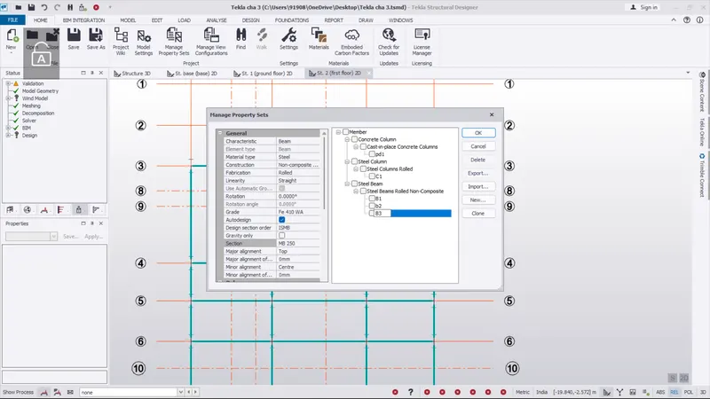
- Here we next create the steel beam property for the project
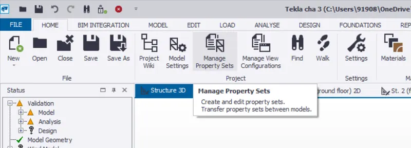
- So go the home tab and select manage property set
- Next we pick the new option and select members and pick the steel beam option
- And set the general setting ,Then ok
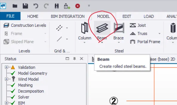
- Then go to the model tab and select the beam option
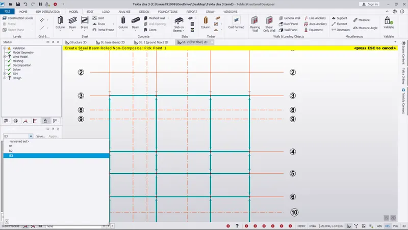
- And select the type of beam in properties box what we want
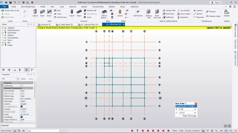
- And go to the first floor and place the beam
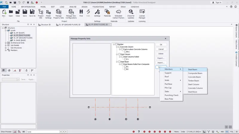
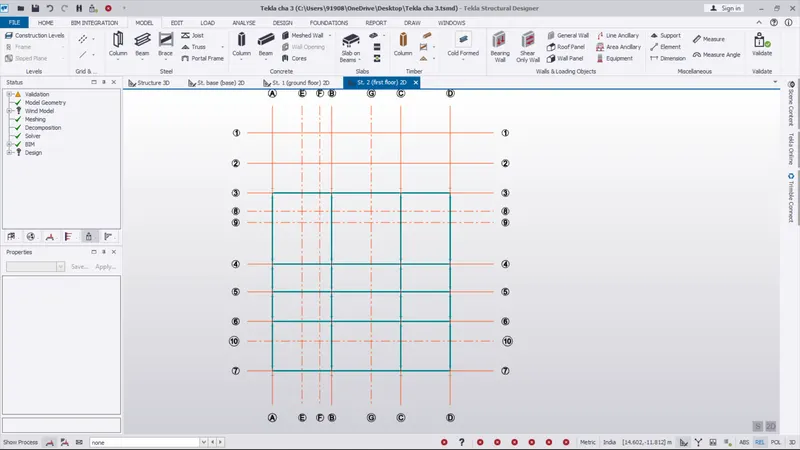
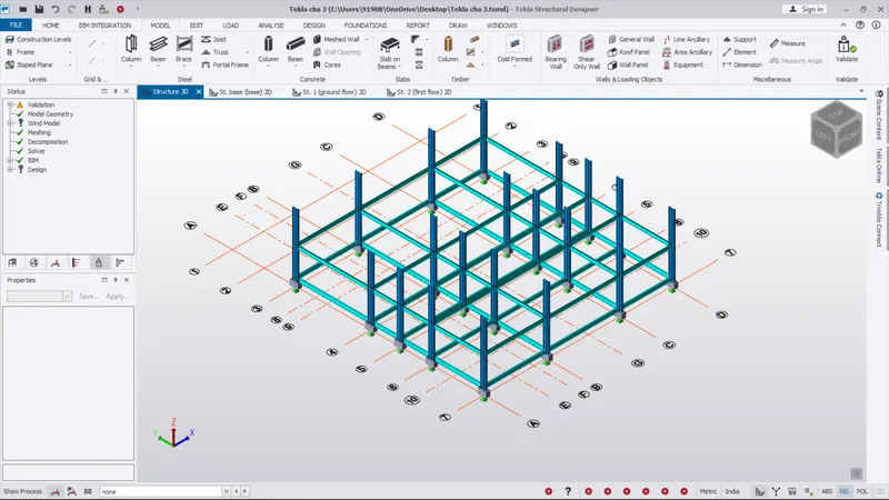
- Again go the home tab and select manage property set
- Next we pick the new option and select members and pick the steel beam option
- And go set the general setting and set ISMB 250 for create the beam in inner side
- Then create the new grid with using a parallel grid option
- The grid can be placed on where wall as been shown in architecture plan
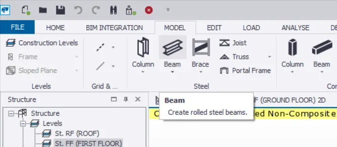
- Then go to the model tab and select the beam option
- And select the type of beam in properties box what we want
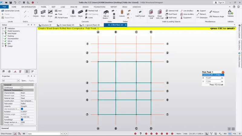
- And go to the first floor and place the beam
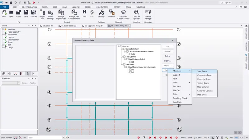
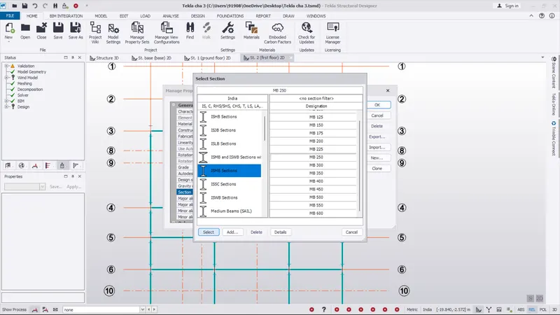
RESULT :
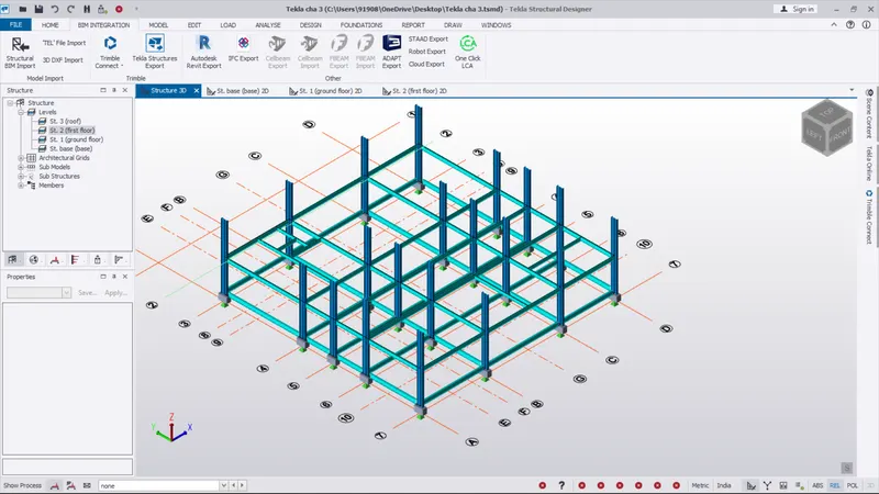
- The steel beam as been created on the first floor and also created in inner side where the wall projection area located on architecture plan
2. Create rafter beam on second floor as roof and moment frame action in one direction and add bracings at locations as per the design intent
AIM :
To Create rafter beam on second floor as roof and moment frame action in one direction and add bracings at locations as per the design intent
INTRODUCTION :
Structural steel beams are iconic to modern architecture. Not only do they look great, but steel’s strength makes it a timeless and practical material. There are strict quality standards in place pertaining to steel beam shape, size, composition, and storage practices. The most common types of structural steel beams include the I-beam, L-beam, and T-beam, which come in regular, tapered, and semi-tapered. These shapes are usually achieved by hot or cold rolling but there are others that are made by welding plates, either flat or bent.
A single construction project usually uses different types of materials and different kinds of structural steel beams in order to achieve the desired result. Building materials can consist of structural steel, which is available in many different forms, as well as concrete, wood, clay, and mortar, to name a few. If the structural frame of a building will be utilized for load bearing applications, then structural steel is considered to be the most suitable material for this purpose.
The majority of industrial and commercial buildings are constructed with either structural steel beams or reinforced concrete. During the design process, it is the job of the engineer to identify which of the two (or combination of the two) will be used to achieve the best result possible. There are many things that need to be considered when deciding on what construction material will be used. Factors include availability, weight, fire resistance, strength, sustainability, and constructability.
PROCEDURE :
- Here we want to create the beam on roof level
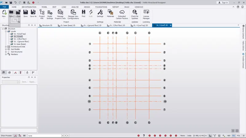
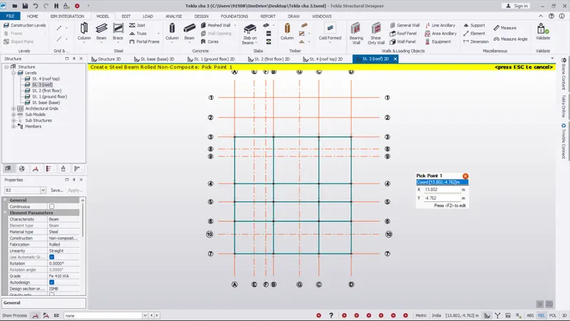
- As per the same above question process the beam as been created on the roof level
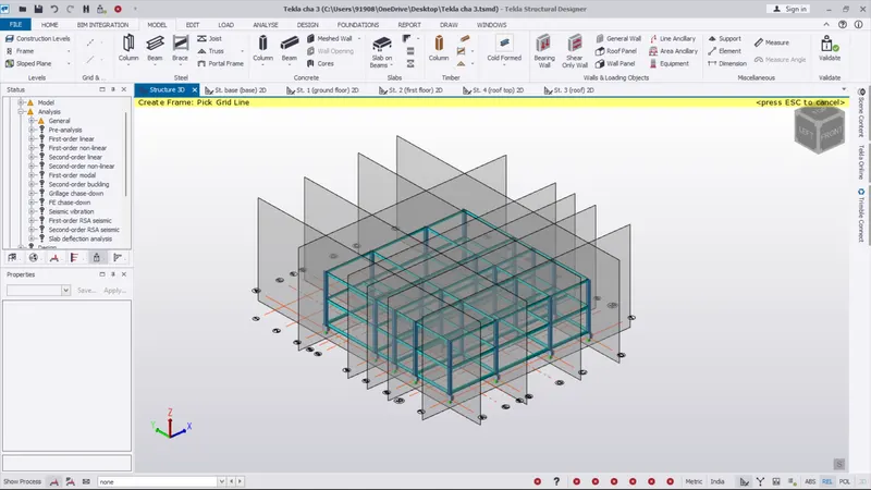
- In all the floor level the beam created image as been shown in below image
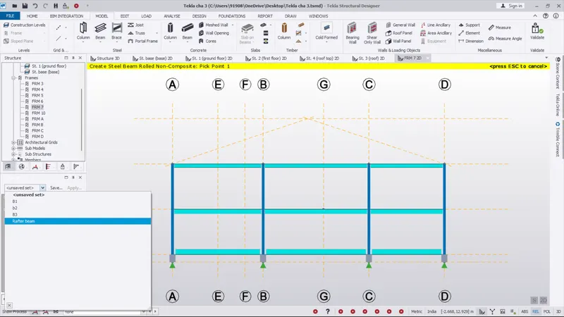
- Next we want to create the rafter beam
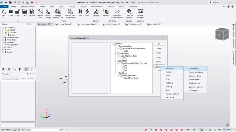
- So go the home tab and select manage property set
- Next we pick the new option and select members and pick the steel beam option
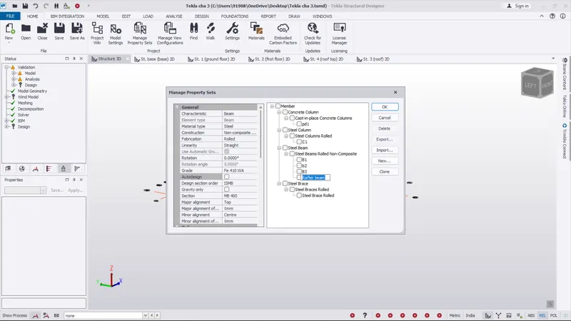
- Rename the beam as " rafter "
- And go the general setting and set ISMB 400
- After creating the rafter beam. Then next go to the model tab
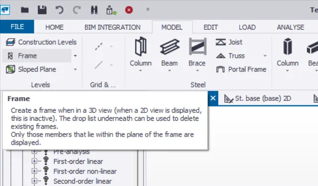
- Select the frame option
- Set the 3d screen
- And place the frame on the all the grid option
- Then the frame as been created automatically
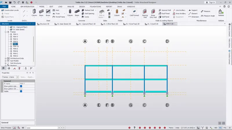
- Go to the structure box on the left side of the screen
- Then select the frame option and select the frame what we want
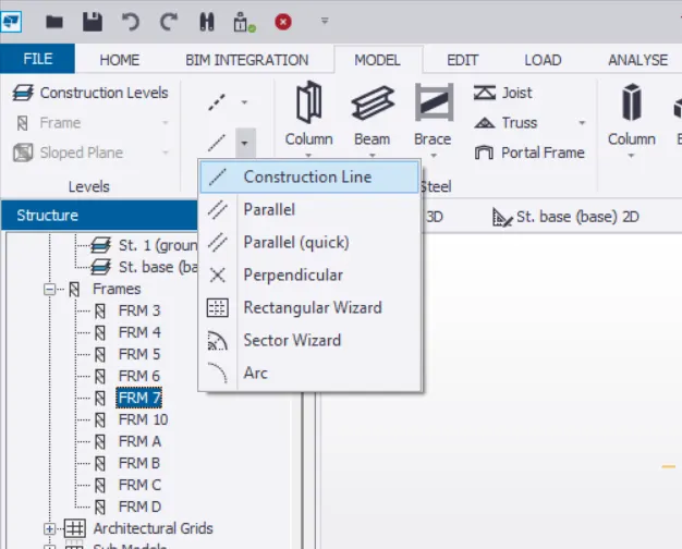
- Go to the model tab
- select the construction line and pick the frame 7
- Draw the construction line at mid point of A to D
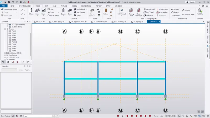
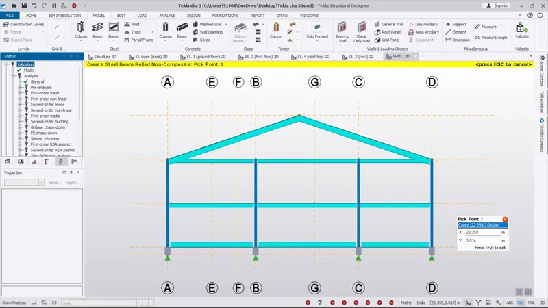
- Draw the rafter beam on the grid with cone shape
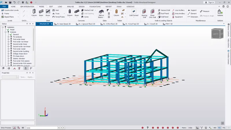
- The rafter beam as been shown in below the image
- Select the rafter beam and right click and copy the beam
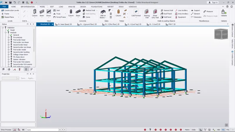
- pick the reference line and copy to all the grid
- Next we want to create the steel brace
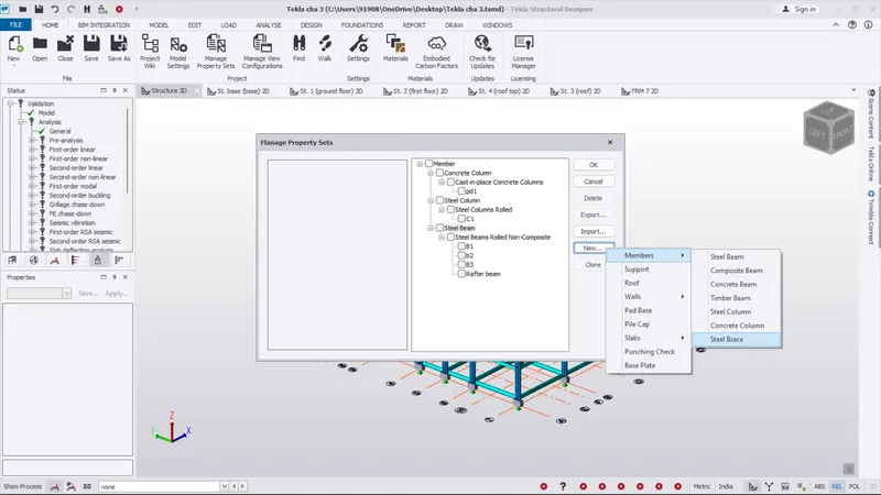
- So go the home tab and select manage property set
- Next we pick the new option and select members and pick the steel brace option
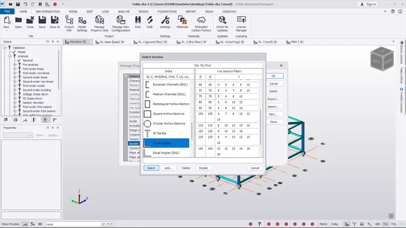
- And go the general setting and go to the section option
- Select the equal angles and select the 75 75 5 6 8 10
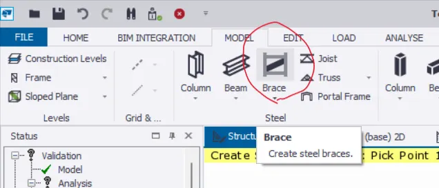
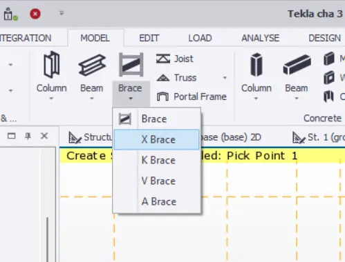
- And select the X brace option on the model tab
- Go to the properties box select the created brace option
- Next go to the frame
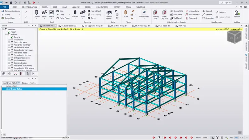
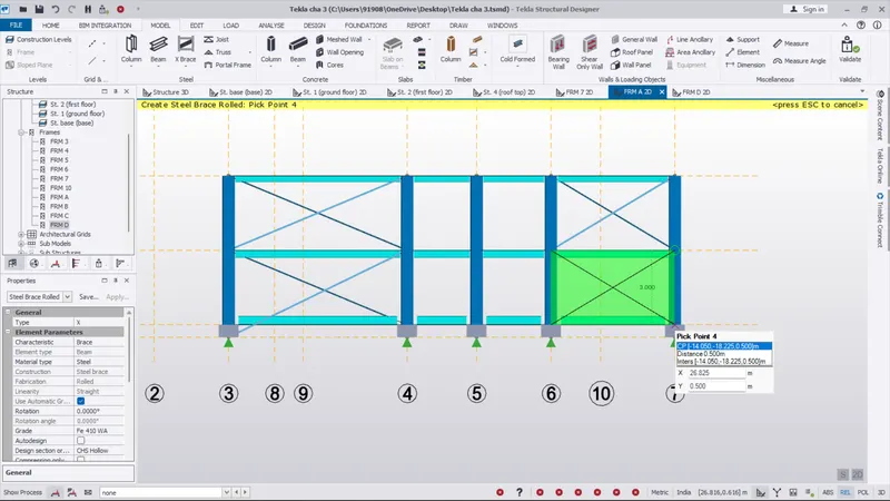
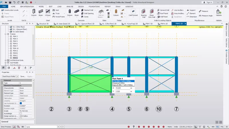
- And draw the X brace on the floor
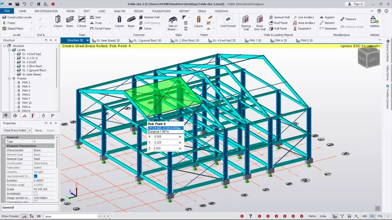
- And turn the screen on 3d and draw the X brace on the roof top
- The completed brace image as been shown below
RESULT :
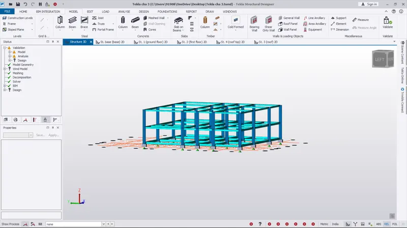
- As per the question all the rafter beam and frame and also the brace are placed and completed on the project
- The completed image as been shown in below