Introduction to REVIT concepts
Introduction to REVIT concepts
AIM :
To study about the concept of revit software
INTRODUCTION :
A detailed introduction and development course for modelling and designing using Autodesk Revit. This course consists of an introduction to Autodesk Revit and using modelling tools to create residential, commercial and industrial units. Introduction to the National Building Code and modelling in Revit following the code provisions. Detailed use of Revit in creating views and rendering views to the cloud. This coursework is aimed to inculcate collaborative and coordination based modelling which reflects the industry's approach towards Autodesk Revit. In addition to learning design skills, this course provides tutorials on drafting standards and using Autodesk Revit to create clean and error-free drawings.
USES OF REVIT :
Revit is a commercial building information modeling (BIM) software by the company Autodesk. It's generally used by architects, structural engineers, mechanical, electrical, and plumbing (MEP) engineers, designers, and contractors. Autodesk Revit allows users to create, edit, and review 3D models in exceptional detail
QUESIONS :
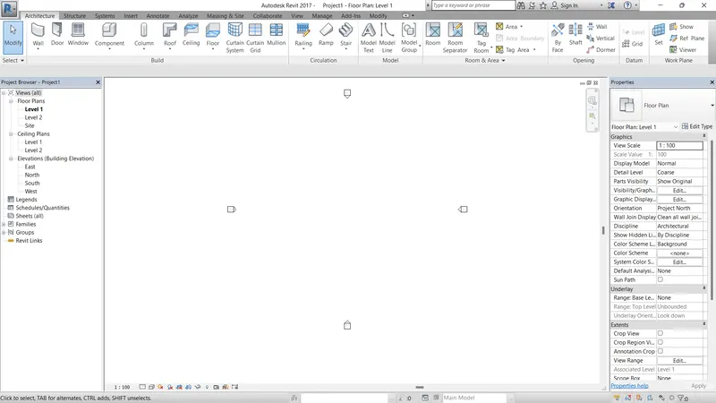
1) From the file menu, create a new project (Structural / Architectural / Construction template ) and name the project appropriately
PROCEDURE :
- JUST OPEN A SOFTWARE REVIT
- CLICK ON THE NEW PAGE
- SELECT THE TEMPLATE
- USE THE ARCHITECTURAL TEMPLATE
RESULT :
2) Save the new project file. Close and open using icons from file toolbar
PROCEDURE :
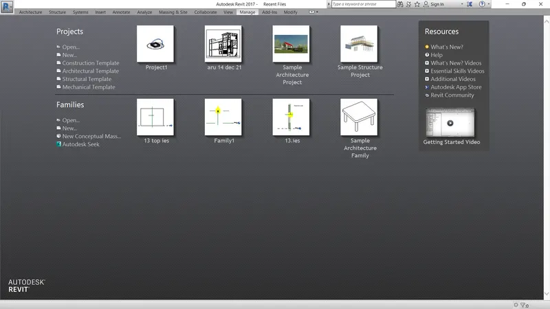
- SAVE THE PROJECT NAME WHAT U WANT (PROJECT 1)
- CLOSE THE FILE
- AGAIN OPEN AND SELECT THE FILE U SAVED
RESULT :
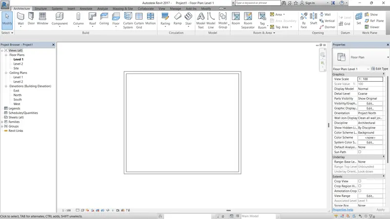
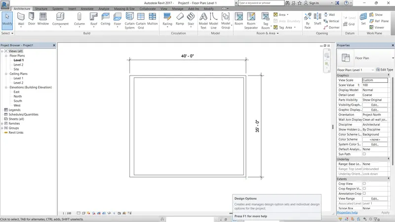
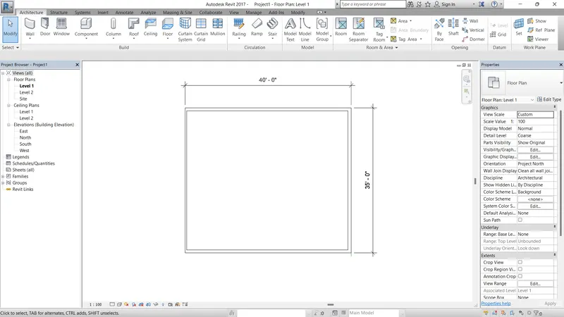
3) From the architecture/ structure toolbar familiarize with options to draw a wall. Create a rectangular layout of walls of about 40’-0” X 35’-0”
PROCEDURE :
- JUST TYPE THE UN AND ENTER IT
- IT WILL OPEN THE UNITS TEMPLATE AND THE UNIT TO FEET AND INCHES
- SELECT THE ARCHITECTURE TAB
- USE THE ARCHITECTURAL TEMPLATE
- AND DRAW THE LINE USING WALL OPTION AS SIZE OF 40' X 35'
RESULT :
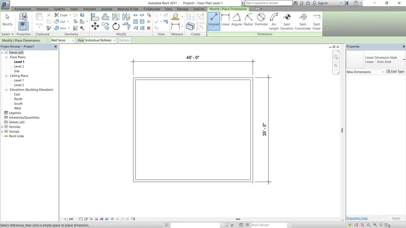
4) From the Annotate toolbar use the aligned option to add dimensions to the layout
PROCEDURE :
- USING THE ANNOTATE OPTION
- USE THE ALIGNES TOOLS
- MARKING THE DIMENSION OF WALL
RESULT :
5) Use the properties browser to switch to different wall types
PROCEDURE :
- AFTER DRAWN THE WALL
- JUST SELECT WALL OPTION
- AND SELECT THE WALL TYPES IN PROPERTIES BROWSER
- PICK THE WALL WHAT U WANT TO CHANGE AND CHANGE THE WALL
RESULT :
6) Create a 3D view from the view toolbar and save the view with the appropriate name
PROCEDURE :
- OPEN A PROJECT 1
- CLICK ON VIEW TAB AND TAKEN ON 3D VIEW
- SAVE THE VIEW
RESULT :
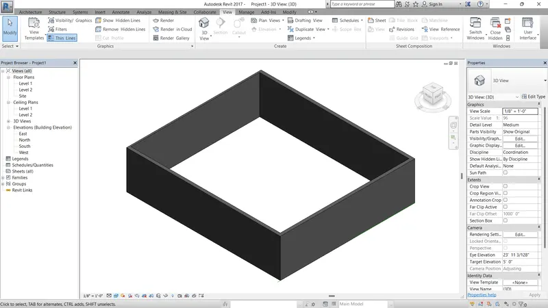
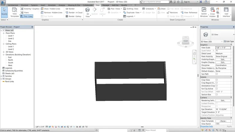
7) Navigate through the 3D model using the view cube. Orbit/pan through the model layout created
PROCEDURE :
- OPEN THE PROJECT 1
- USE THE NAVIGATION TOOL ON RIGHT SIDE
- THEY HAVE SOME OPTION JUST CLICK THE ORBIT OPTION
- AND ROTATE THE VIEWS
RESULT :
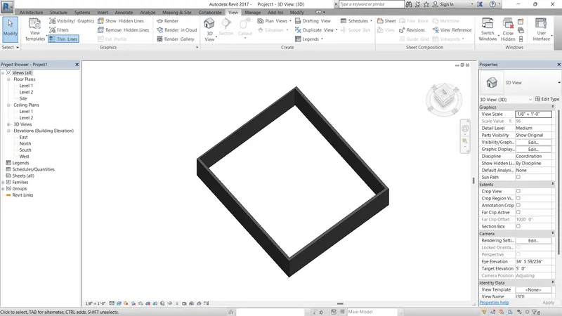
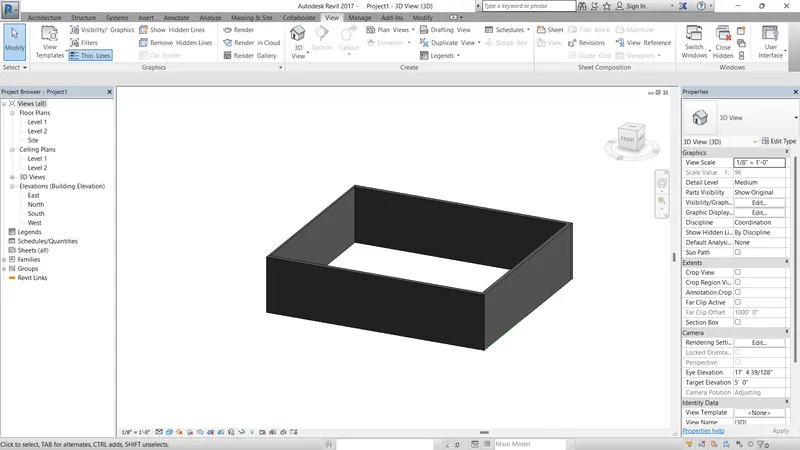
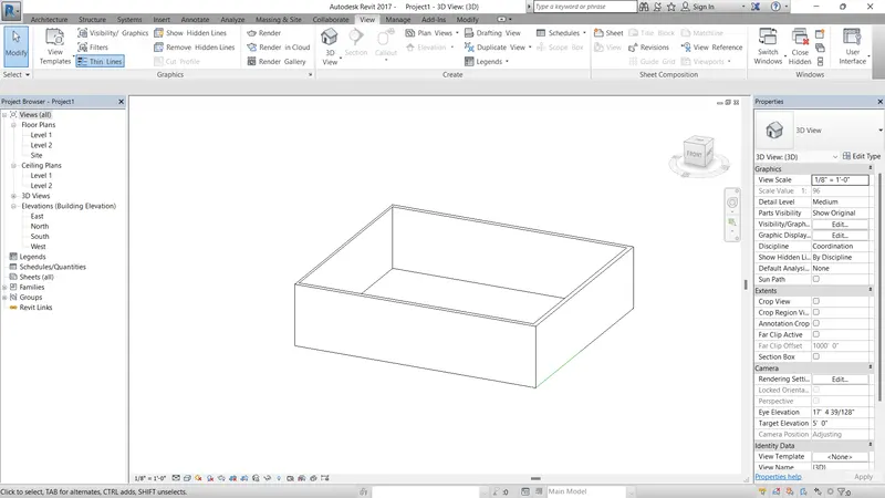
8) Use the visibility settings option below to switch model to shaded, realistic, hidden lines options
PROCEDURE :
- OPEN PROHECT 1
- TAKEN ON THE VISUAL STYLE PRESENT AT THE BOTTOM OF SCREEN
- THEY HAVE MANY OPTION, JUST U TAKE A WIRE FRAME, REALISTIC, SHADED
RESULT :
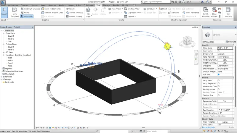
9) Turn the sun path on and off to view shadings in the layout created
PROCEDURE :
- OPEN PROHECT 1
- TAKEN ON SUN PATH OPTION IN BELOW THE SCREEN
- TURN ON THE SUN PATH
- GO TO THE SUN SETTING AND SELECT WANT U WANT
RESULT :
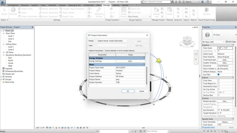
10) Use the Manage toolbar to enter project settings, project name, and project issue date (choose according to your convenience).
PROCEDURE :
- OPEN PROHECT 1
- TAKEN THE MANAGER TOOL
- CLICK THE PROJECT INFORMATION
- ENTER THE PROJECT DATE, TIME, NAME, COMPANY
RESULT :
11) What is the Analyze toolbar used in Revit? How it is beneficial for design and modeling
- To evaluate performance of the project using boundary conditions and loads.
- Different load combination are applied and revit analysis these loads, thus giving efficient load combination for the building.
- Therefore it can analyse conceptual design in several ways such as area analysis, energy analysis, heating and cooling loads analysis and analyse effects of structural loads.
- Energy analytical model is based on conceptual mass, building elements or on both depending on analysis mode. Heating and cooling loads analysis is performed to determine energy demands of the building.
- Sustainability is crucial nowa days in construction process, energy optimization in revit is useful to maintain sustainability of the design.
12) What are the links that Revit supports to be linked to the model?
- Link REVIT: Using this link between two Revit models can be created i.e., one past and one current file. It specifies the relative locations of the individual buildings on campus or coordinates efforts across disciplines (Architectural, structural, and engineering).
- Link IFC: The Industry Foundation Classes (IFC) data model is intended to describe architecturally, building, and construction industry data. It is a platform-neutral, open file format specification that is not controlled by a single vendor or group of vendors. Link to an IFC file when you want to perform additional design work in Revit using the IFC file as a reference.
- Link CAD: When you link a CAD file to a Revit model, Revit maintains a link to that file. Whenever you open the model, Revit retrieves the current, saved version of the linked file and displays it in the model. Any changes to the linked file are displayed in the model. If the linked file changes while the model is open, reload the file to retrieve the latest changes This ability to retrieve the latest changes to a CAD file is the difference between linking and importing. When you import a CAD file, Revit uses the version of the file that you imported. It does not retrieve or display changes to the imported file.
- Link Topography: When a civil engineer or a landscape architect creates topography data for a project and you want to reference it for a building model, you can link the topography to Revit.
- Link DWF Markups: When creating construction documents, a typical workflow is to print out a sheet, have it reviewed and marked up by the project architect or other professional, and then return it to the originator of the sheet to havethe requested changes made.Link Decals: Use the Place Decal tool to place images on surfaces of a building model for rendering
- Link Point Cloud: Link a Point Cloud file into the project to provide a highly accurate visual reference of the existing condition of a building or site.
13) Why do you need the Collaborate tab in Revit? How it supports modeling and its efficiency
- Collaboration tool offers users such as structural engineer and MEP engineers to work simultaneously.
- It enables cloud file, collaborate with it with multiple instances of independent files. It creates complete building model by bringing different models together.
- It enables to understand changes in the model and any conflicts occuring in the design when it is linked together. Thus it enables to design an optimized and efficient building model Suppose to link revit file to Current file (structural file), make a copy of current file and name it as MEP file.
- Link both the files and thus it enables to work on both files simultaneously.