To Analysis and Design of Steel Structures using TSD
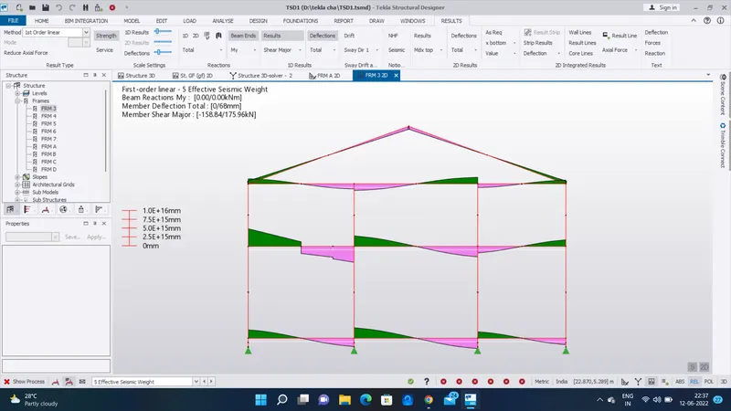
1.) Summarize your study for the bending moment, shear force and deflection diagrams for the elements of the model
AIM :
To Summarize your study for the bending moment, shear force and deflection diagrams for the elements of the model
INTRODUCTION :
- Shear Forces occurs when two parallel forces act out of alignment with each other. For example, in a large boiler made from sections of sheet metal plate riveted together, there is an equal and opposite force exerted on the rivets, owing to the expansion and contraction of the plates.
- Bending Moments are rotational forces within the beam that cause bending. At any point within a beam, the Bending Moment is the sum of: each external force multiplied by the distance that is perpendicular to the direction of the force.
PROCEDURE :
STEP: 1
- Open the tekla software and open the file previously doned
- Go to the load tab and select the seismic load
- Select the code spectra and pick Next
- Basic information --> Next
- Structural irregularties --> Next
- Fundamental period --> Next
- Seismic force resisting system --> steel building with OMRF --> Next
- Effective seismic weight --> export all load to right side --> Next
- Localization --> Next
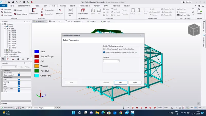
- Initial parameters --> Replace only combination --> Next
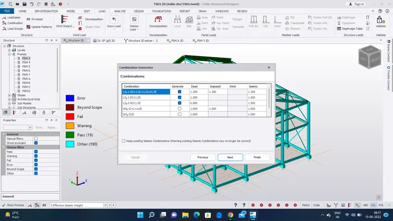
- Combination --> Next
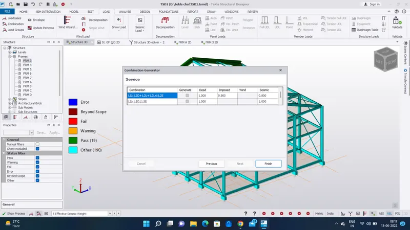
- Service --> Next
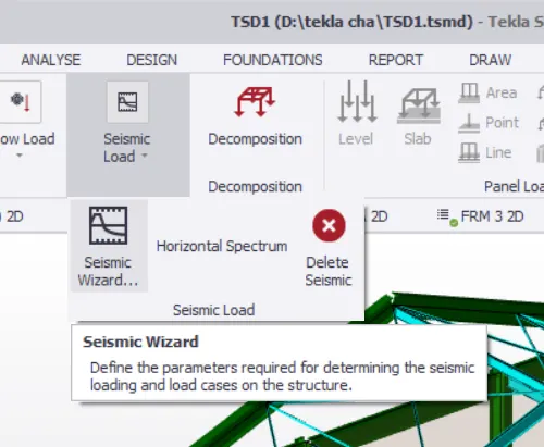
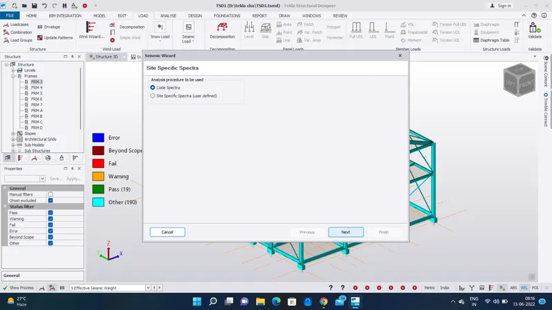
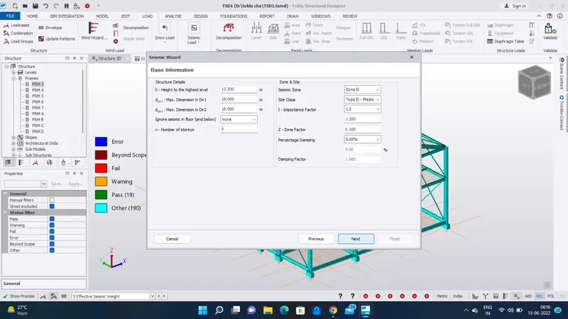
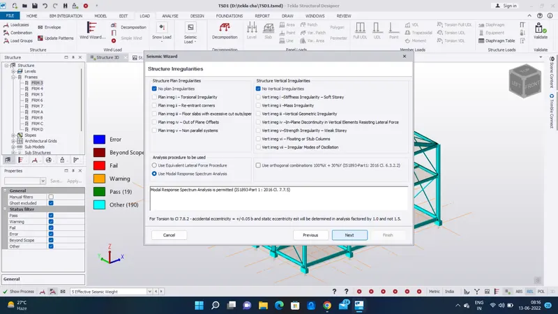
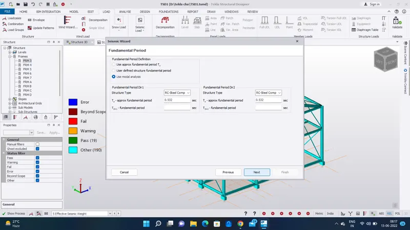
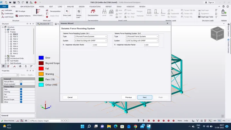
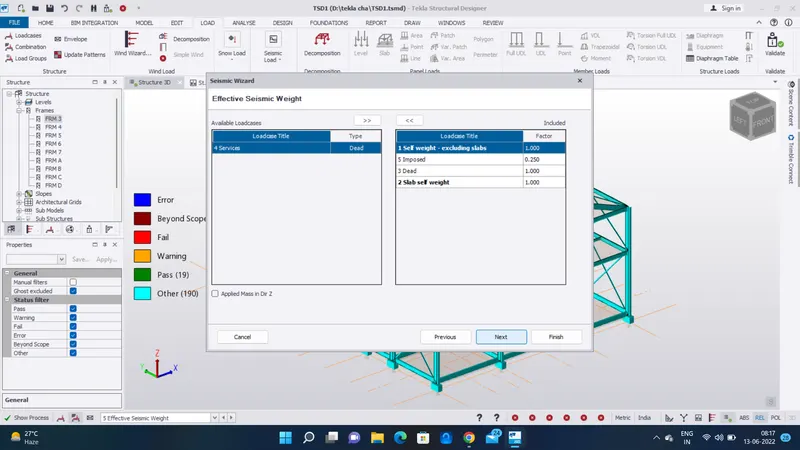
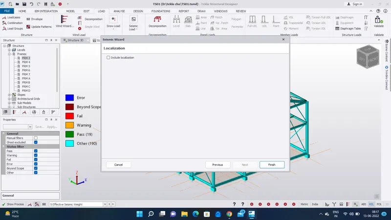
STEP: 2
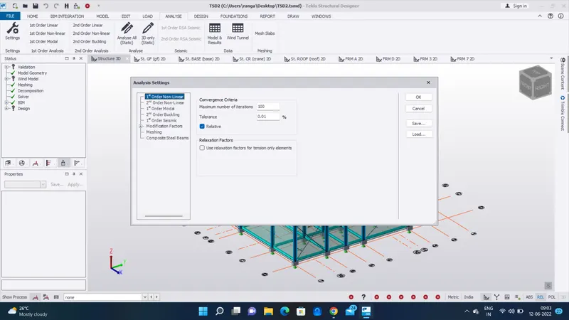
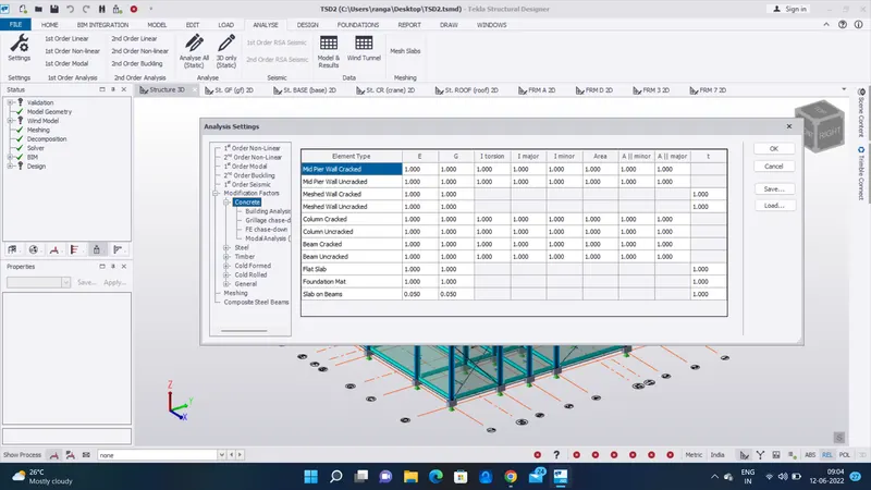
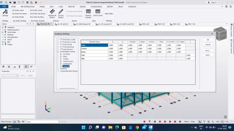
- Next go to the analysis tab and pick the setting option
- In there select 1st order non-linear and check once 100 and 0.01%
- And also check the concrete and general option once then click ok
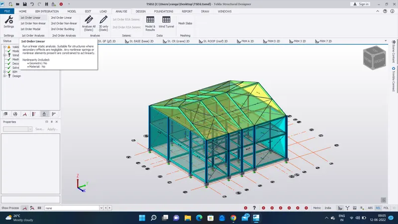
- finally pick the analysis option and select the 1st order linear
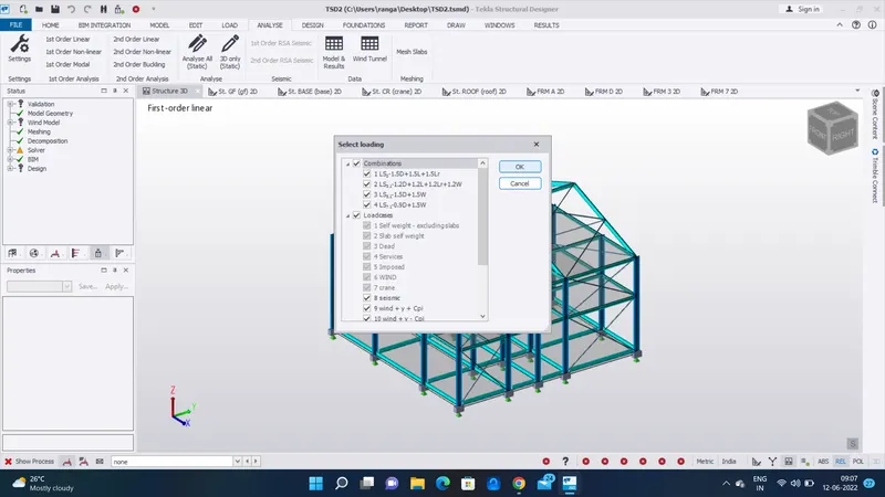
- select all combination and load cases option and then click ok
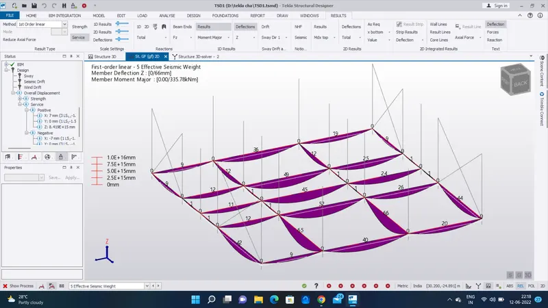
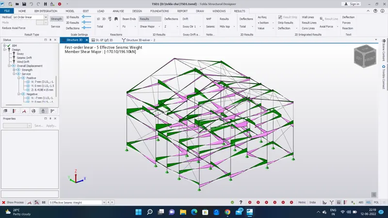
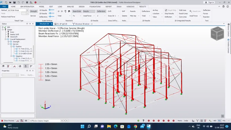
- Go to the ground floor and select the result tab
- And also select the deflection and select the load cases
- Then we want to check the moment major, shear major, and Axial force
STEP: 3
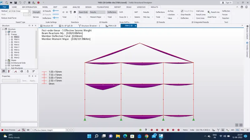
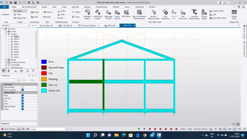
- Select the frame 3 and check the deflection
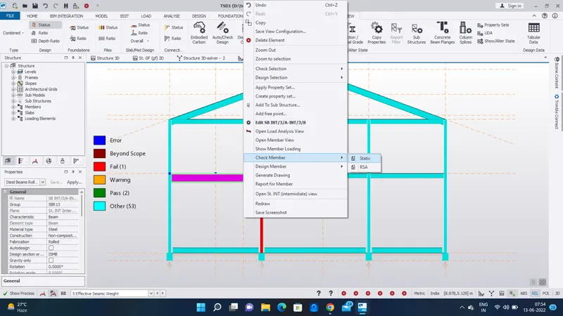
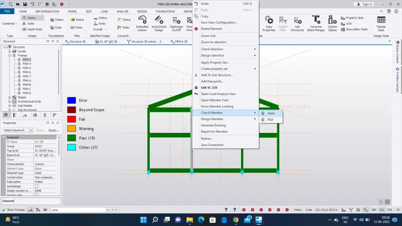
- Select one beam and then right click
- Go to the check member --> static
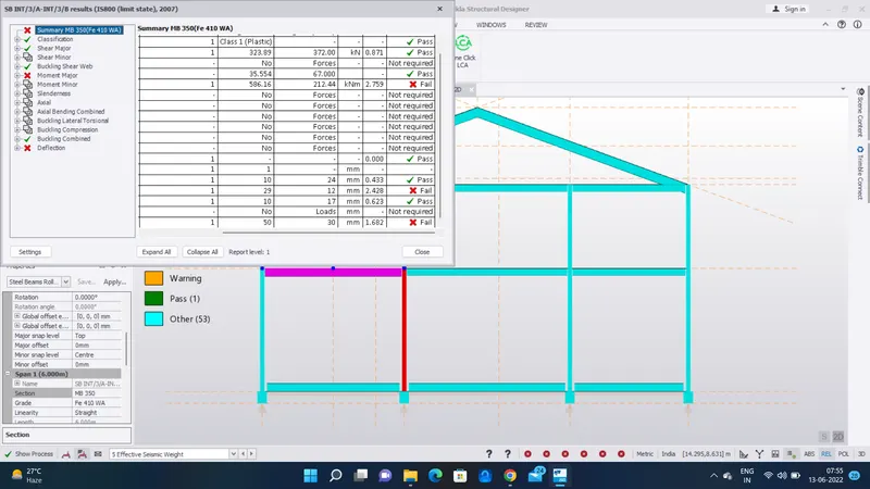
- I got a some mistake in moment major and deflection
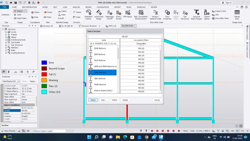
- So First we want go to the property template
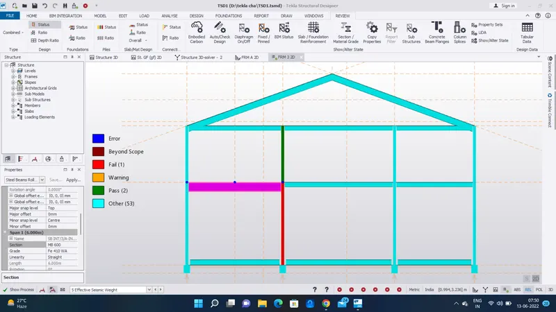
- And chamge the beam size 350 --> 600
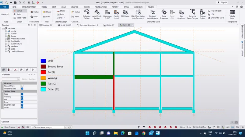
- And again analysis the model
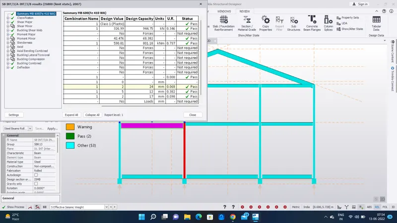
- And go to the same beam and right click and select the check member --> static
- now i got all member passed
STEP: 4
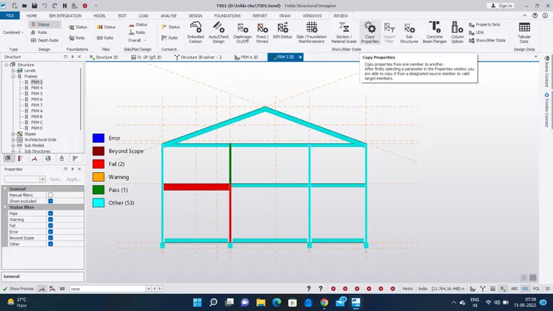
- Taken a passed beam go to the review screen
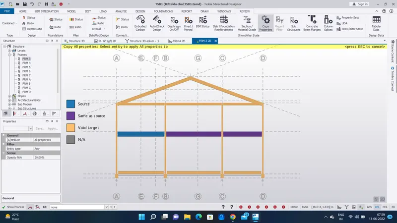
- And use the copy monitor option
- Copy the passed beam to other failed beams
- Finally all beams are passed
- Next we want to check the column
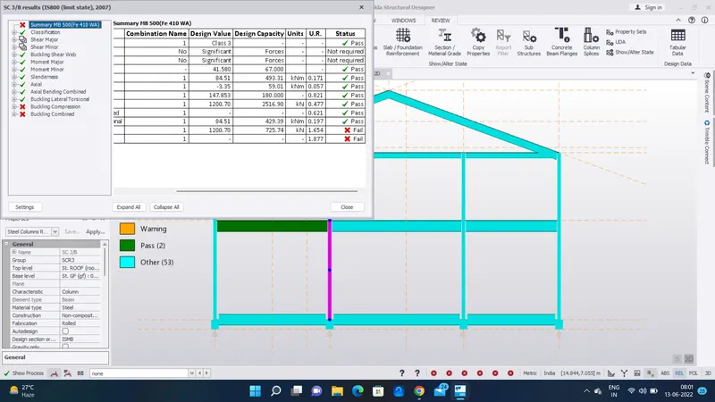
- Select the column And right click the column and select check member --> static
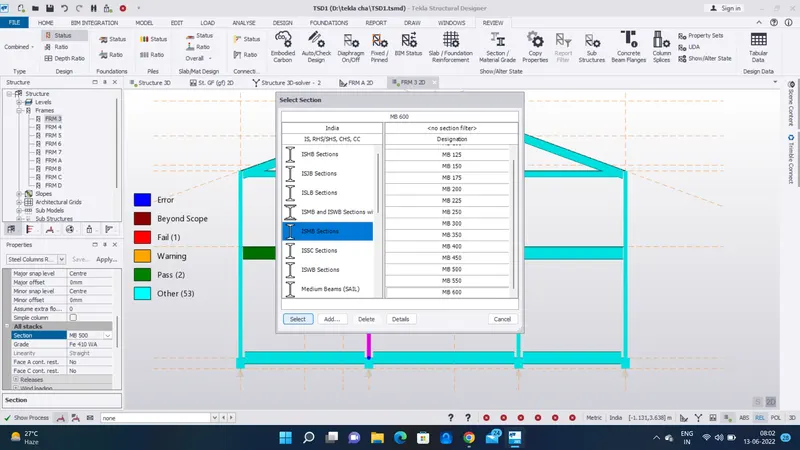
- And column as been failed
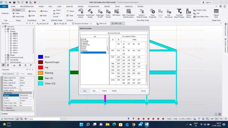
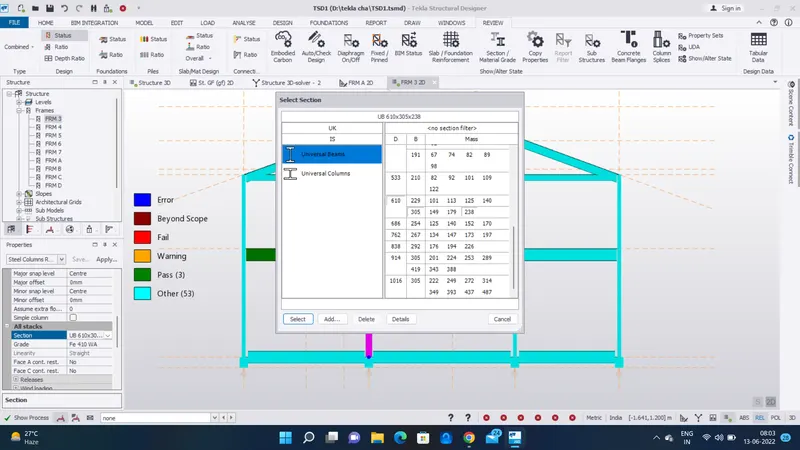
- So go to the column properties template and change the section ISMB (Indian - UK)
- And select 610X305X238 THEN OK
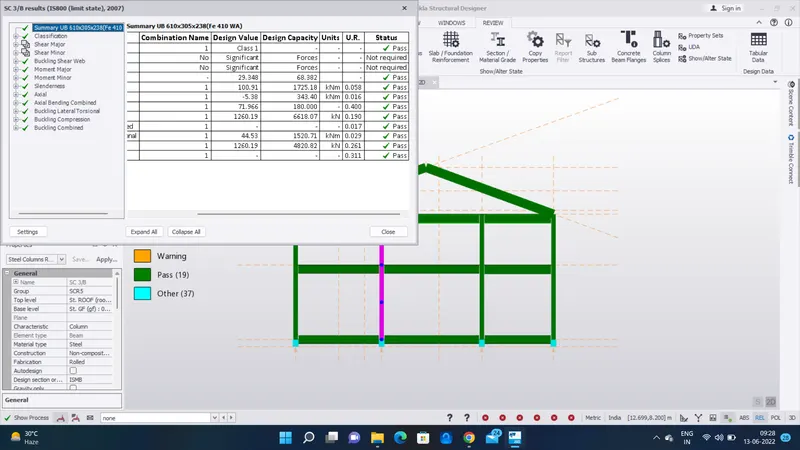
- After check with using check member --> static and my column as been passed
- Again using the copy monitor option and copy all passed column to failed column
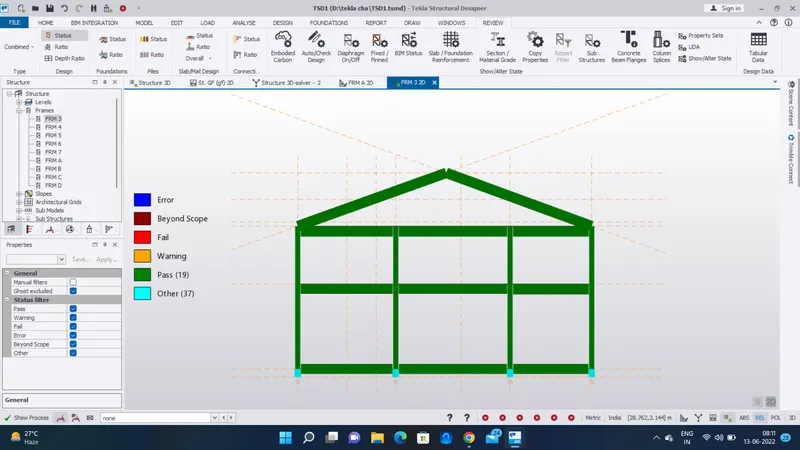
RESULT :
As per the question the bending moment, shear force and deflection diagrams for the elements of the model as been checked and passed
2.) Based on the analysis design the members and outline the thought process in selecting the member sizes along with the foundation design
AIM :
To Based on the analysis design the members and outline the thought process in selecting the member sizes along with the foundation design
INTRODUCTION :
- Shear Forces occurs when two parallel forces act out of alignment with each other. For example, in a large boiler made from sections of sheet metal plate riveted together, there is an equal and opposite force exerted on the rivets, owing to the expansion and contraction of the plates.
- Bending Moments are rotational forces within the beam that cause bending. At any point within a beam, the Bending Moment is the sum of: each external force multiplied by the distance that is perpendicular to the direction of the force.
PROCEDURE :
STEP: 1
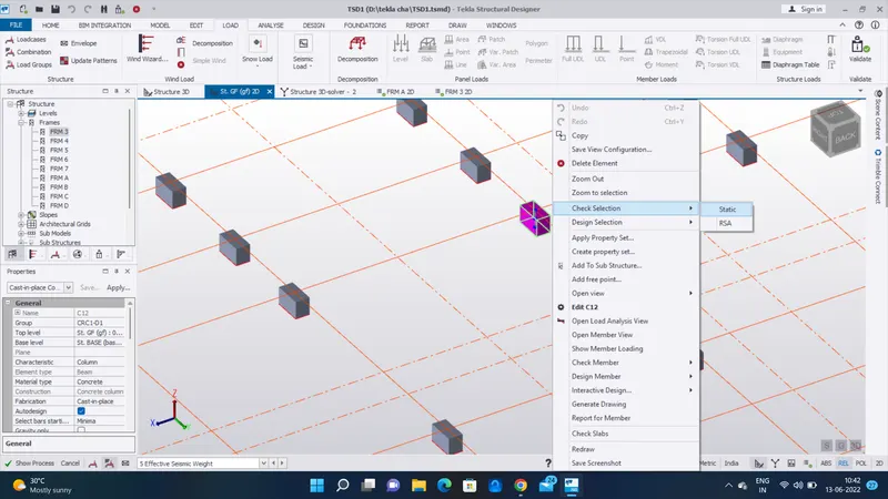
- Next we want check the foundation concrete column
- Select the concrete column
- And go the the check selection --> static
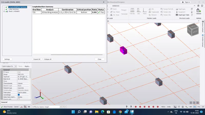
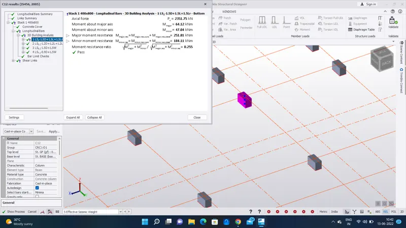
- Concrete member has been passed
- Then load combination calculation as shown there and we can check it
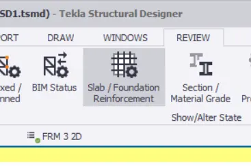
- Next go to the review screen
- And select the (slab/foundation reinforcement) option
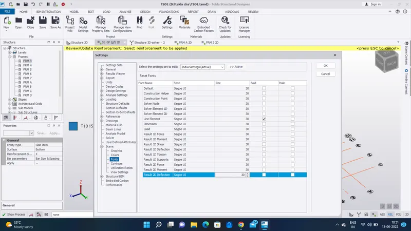
- And go to the home option and select the setting
- And go to the scene --> font change all values to 30
STEP: 2
- Next again go to the review tab
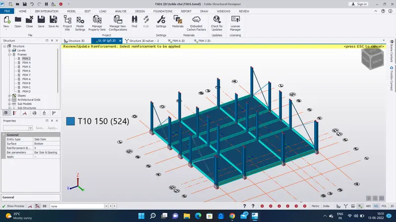
- And Select the (slab / foundation reinforcement) option
- There the reinforcement size has been shown
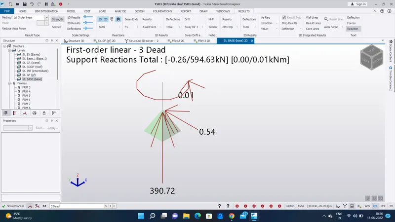
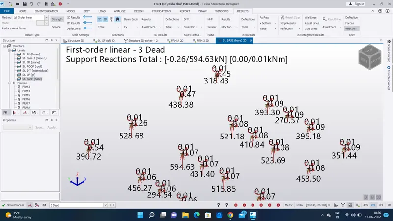
- Next we want to check the reaction so select reaction option on review tab
- And check the Mx, My, Mz reaction
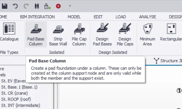
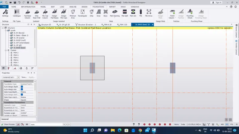
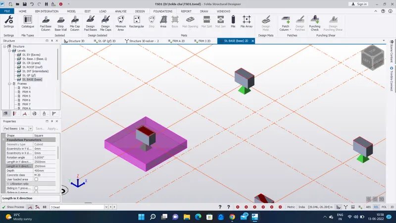
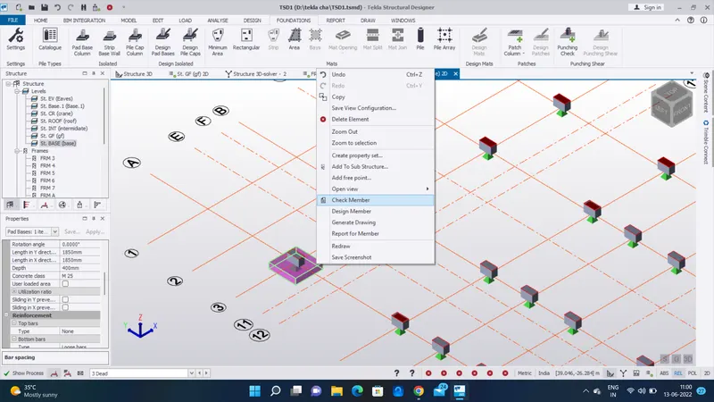
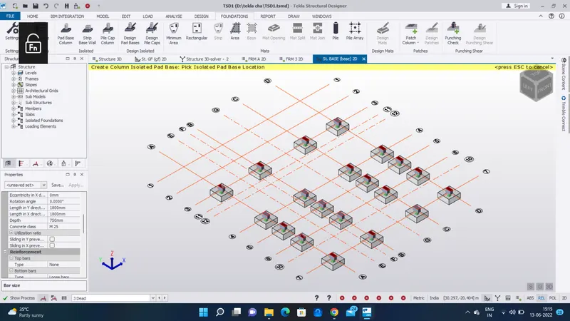
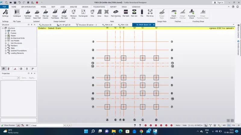
- Next go to the pad base option and place the pad base on the footing
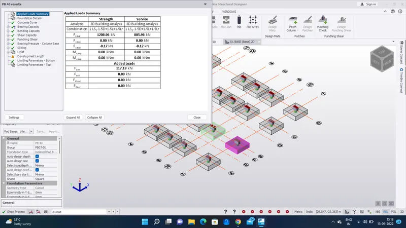
- Next check the pad base with use of check member --> static
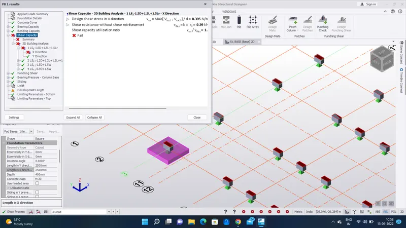
- I got some fail on shear capacity
- So change the grade M25
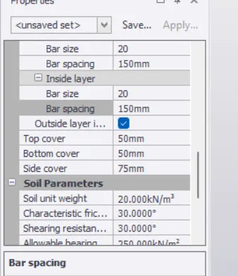
- Change bar size and bar spacing 20 and 150 and analysis
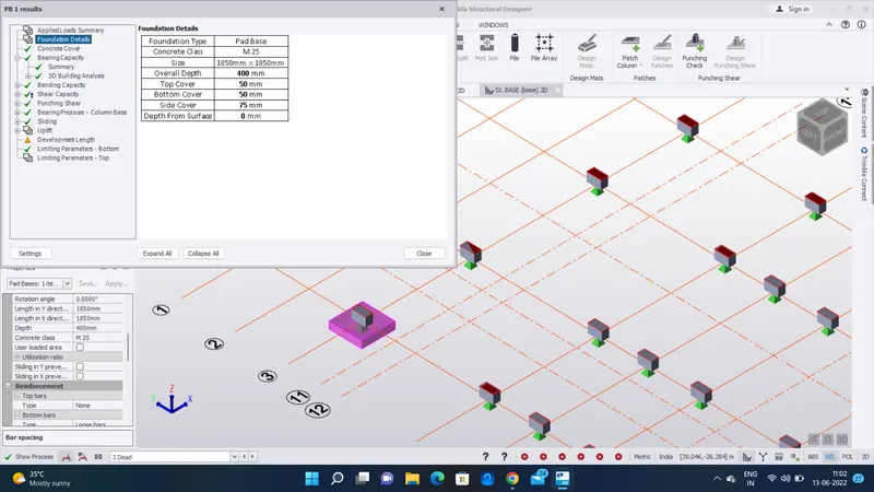
- Again check the pad base on check member --> static
- Now pad base are passed
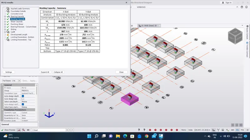
- And also we saw a bending capacity calculation
RESULT :
As per the question the analysis design members and outline the thought process in selecting the member sizes along with the foundation design as been doned