Project 1 _Creating an Architectural plan for the provided plot size and develop relevant basic structural drawings
Creating an Architectural plan for the provided plot size and develop relevant basic structural drawings
AIM :
To draft and Creating an Architectural plan for the provided plot size and develop relevant basic structural drawings.
INTRODUCTION :
- Architectural drawing is simply the technical drawing of a house, a building or any kind of structure. Technical drawings are graphic representations such as lines and symbols that follow specific conventions of scale and projection. ... They may use them to indicate the overall appearance, inside or outside the building.
- The architectural drawing showing the
@ Architectural drawing :
1. Architectural drawing for floor plan,
2. Architectural drawing for elevation,
3. Architectural drawing for section,
@ Structural drawing :
1. Structural drawing for beam,
2. Structural drawing for column,
3. Structural drawing for footing,
COMMAND USED :
-
NAME COMMAND LINE (L) ENTER RECTANGLE (REC) ENTER CIRCLE (C) ENTER ERASE (E) ENTER COPY (CO) ENTER MOVE (M) ENTER TRIM (TR) ENTER MIRROR (MI) ENTER OFFSET (O) ENTER EXTEND (EX) ENTER ARRAY (AR) ENTER ROTATE (RO) ENTER DIMENSION (DIM) ENTER TEXT (T) ENTER FILLET (F) ENTER
PROCEDURE :
@ Architectural drawing :
1. Architectural drawing for floor plan,
- Here we detailed about the floor plan by architectural design
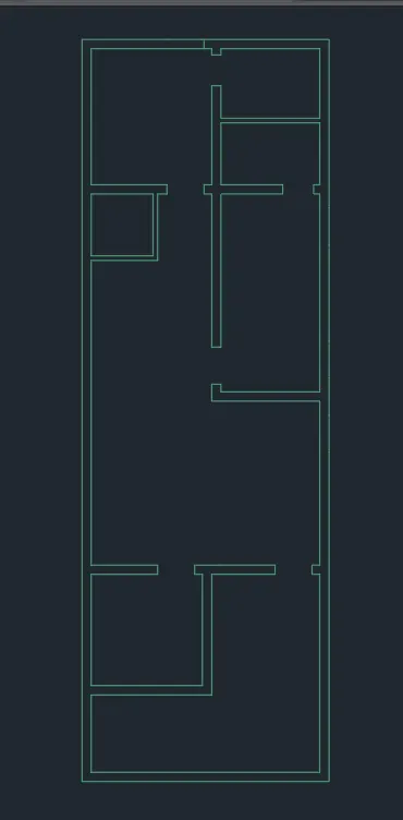
- First we use the line command for draw the plan of ground floor and first floor
- And we use the offset command for offset the line to make a wall 9" and partition wall 4.5"
- Trim the line by using trim command
- And also we want to trim the wall for making the door
- Then the the door size is an
D : 915 X 2314 MM
D1 : 762 X 2032 MM
D2 : 915 X 2314 (DUAL DOOR)
- We want to make the door by using LINE command and ARC command for draw the door
- And also draw the window by same like as using line command and then the window size is
W : 915 X 1220
W1 : 406 X 1220
- Now we use the copy or move command for copy or move the door and also window and place it multiple time it is easy and short way for draw the plan
- If you want the door direction can different angle then we can also use the rotate command for easy the way
- Use the command of rectangle, circle, arc, polygon for draw the bed, table, chair thats like of furniture what we want
- Use the colour for highlights the furniture, walls, dimension ect.....
- finally use the text command for indicated the dimension where we want, separate separate dimension of rooms indicate seperatly.In the dimlinear command we can change the dim scale, colur, type of standard text used here
first floor:
- first floor drafting is easy by copying method becausen the first floor as same like as ground floor
RESULT :
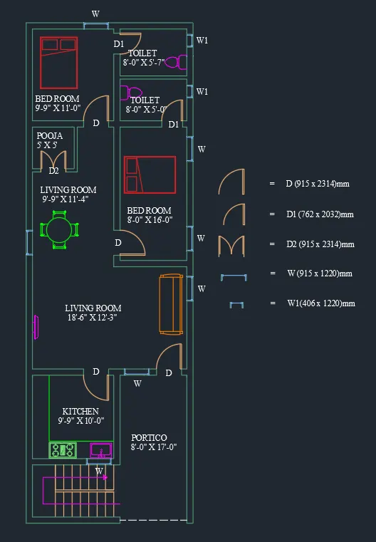
GROUND FLOOR FIRST FLOOR
2. Architectural drawing for elevation,
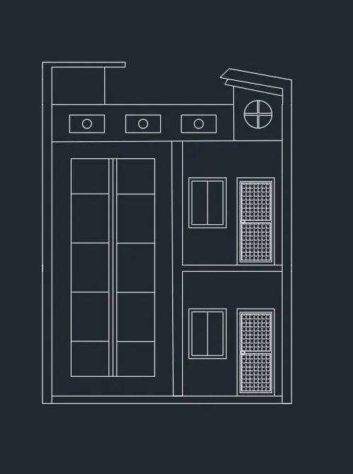
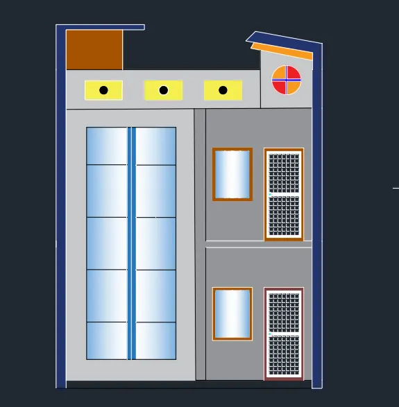
- Elevation is nothing, it can be view the plan as an front side is called elevation
- Using xline for projection the floor plan by draw the elevation
- Elevation is drawn using by line command
- Trim the line by using trim command and also using the same command for extend the line also
- And also we want to trim the wall for making the door
- The elevation majorly used for designed the front look
- here used the hatch for using coloures and different types of line and symbols imported to the drawing
- here i can use the hatch for painting and glass looking designed
- we can imagination the front look as same like as floor plan other then the extra design as used by our own creation design
- door can be height by 7 feet and width can be 3 feet
- window can sill height of 3 feet and window height 4 feet and width of 3 feet
- the design of parapet wall as shown in below the diagram
- the parapet height is 3 feet
- And height of the two floor is 10 feet + 10 feet two floor 20 feet and centerd roof thickness is 6"
- breath of the building is 20 feet.
RESULT :
3. Architectural drawing for section,
- Change the current layer to wall
- Take the xline command
- Pick in the Vertical direction
- The projection can be done by in the floor plan section and also we taken the projection as followed by the elevation
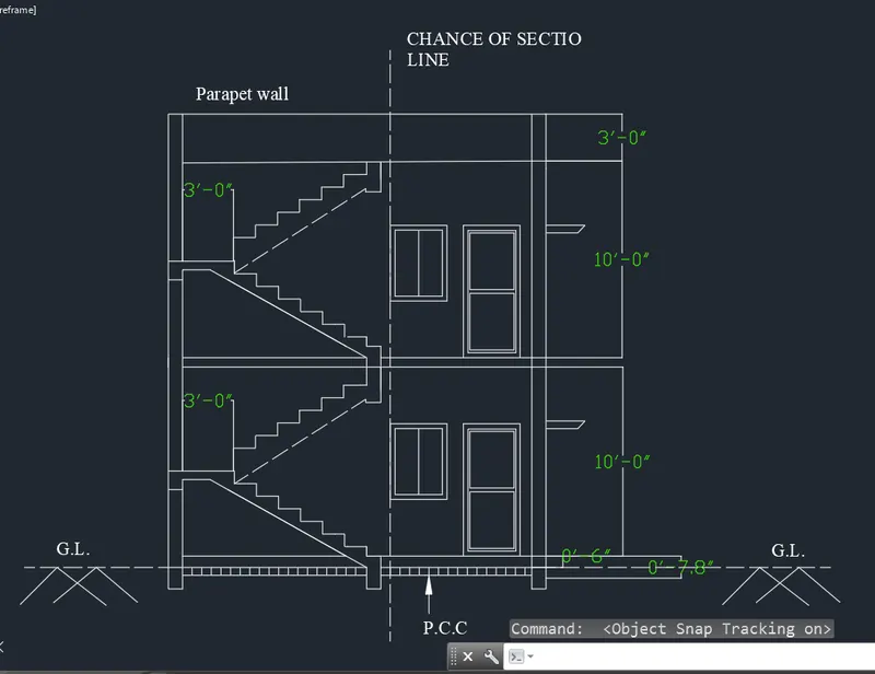
- Offset the line from ground plan to floor plan height as be 10' feet and the thickness of roof is an 6" inch
- For drawing of staircase offset 8 inch for riser and then the thread can be 1' 2"
- Draw the railing of staircase in dash manner from the layers
- Give the dimensions by dim linear or dim Continue command.
- Select the multiline text for naming of the section.
- And the same here also we can used the text command for text the dimension and name.
RESULT :
@ Structural drawing :
Structural drawing for beam,
-
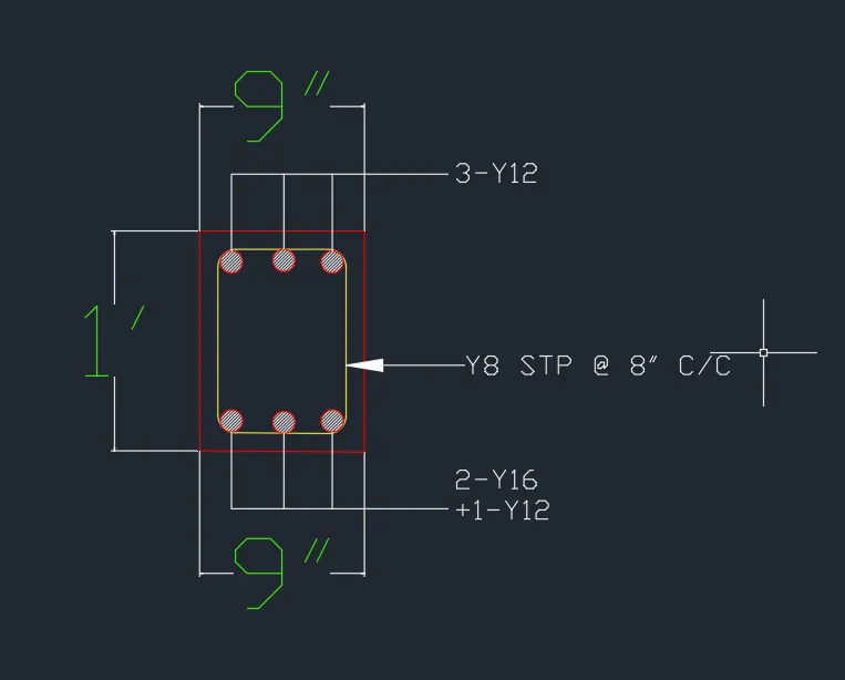
using the coomand of rec enter for draw the rectangle
-
taken C cricle command to draw the reinforcement bar details
-
Then use the offset command for using the offset of reinforcement
-
making a t enter for open the text box for writing the number of bars and size of bars used here
-
Using 'DIMLINEAR'to create a dimension of the plan.
-
we can checking the dimension using dim or di command,
-
using the "SAVE"command to save the Text.
-
Finally the result can be shown by below,
RESULT :
Structural drawing for column,
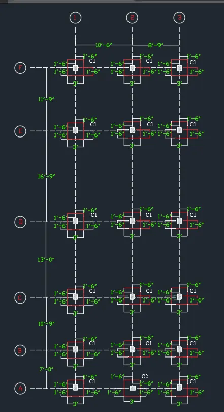
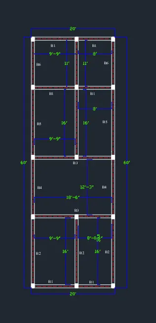
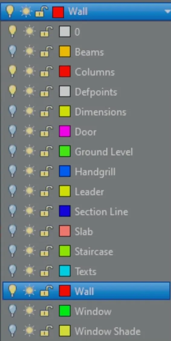
- Turn of the layer expect wall and column by using layer properties it can be shown below.
- take a co (copy) command for easy copy the objects
-
Change the current layer to the center line layer
- Enter Use line command Specify first point anywhere perpendicular of length 115to the internal wall
-
Enter Again take line command Draw a line perpendicular to the last line drawn ,Enter Erase the first center line as per shown below
-
By this similar way, draw the centre line for all the necessary walls It will show us the following result Change current layer to column layer
-
USING rectangle command to show the column
-
Specify corner point anywhere
-
Specify > Dimension,Length > 230, Width> 230
-
use the hatch command
-
Copy that rectangle and place in location as per design requirement Off the layer of the wall, it will show us following result
-
Mark the grid lines as 1,2,3 in Y direction and A,B, etc in X direction
-
Create the circle and insert these above text and place as per shown below
-
Also use the text command to show the C1, C2, etc ,Change current layer to dimension layer
-
Click on ANNOTATION tab
-
Change the layer to dimension layer
-
Click on Dimension
-
Click> Manage dimension style
-
Style name Project
-
Then select linear dimensions Provide the linear dimension having length 319Omm
-
Then take continuous dimension command and provide the center to center dimensions,And similarly this way, provide the dimensions wherever necessary
-
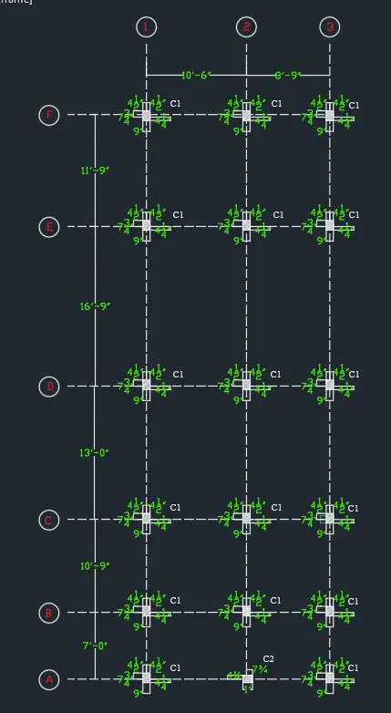
The result the column is shown below
RESULT :
Structural drawing for footing,
- creating the footing by using the rec and line command
- creating the line command by using l enter and creating the footing by using center to centre line of beam
- Create a column and check with dimenson given in the plan ofcolumn size.
- USINGN Offset command to create the footing Size.
- ENTER offset the line to createa Excavation mention in different line.
- All the Lines are Shown in a different Layer to Find.
- show the column dimension and footing size.
- Finally we draw the section footing and show the dimension of the footing column size.
- Click 'DIM'to create a dimension of the plan.
- And check the dimesnion before save.
- And Click "SAVE"command to save the Text.
- Finally we shown the result below.
RESULT :