Project 1 - Meshing of Floor Panel
Meshing of Floor Panel Project
Objective:
To entirely mesh the specified floor panel according to the specified quality criteria without any elemental failure.
Given Quality Criteria is
Target Element Length = 5 Units
| S.N | Quality Criteria | Value |
| 1 | Aspect Ratio | 5 |
| 2 | Skewness | 45 |
| 3 | Warping | 15 |
| 4 | Taper | 0.5 |
| 5 | Min. Length | 2 Units |
| 6 | Max. Length | 8 Units |
| 7 | Min angle Quad | 45 |
| 8 | Max angle Quad | 135 |
| 9 | Min angle Tria | 20 |
| 10 | Max angle Tria | 120 |
| 10 | Tria % | 10 |
Procedure:
Imported model
Figure. 1 shows the imported Floor Panel model in ANSA
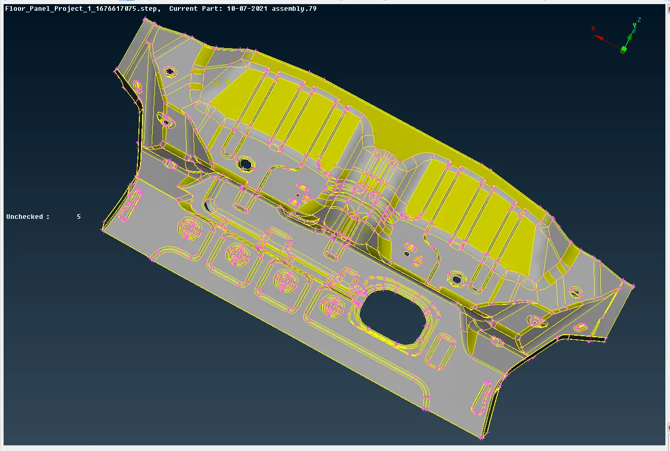
Figure. 1. Imported Floor Panel model
Geometry Clean-up
The next essential stage is checking the model's geometry. This will assist us in eliminating all surface errors, undesirable Cons, as well as any disruptions made to the model. this is done by
Command: Tools+Checks + Geometry.
For the Checks manager dialog box as shown in Figure. 2. Total Errors can be cleared automatically by
Command: Right click + Fix.
In the Checks manager dialog box. Errors can be cleared manually by
Command: Faces+Delete / New, Command: Faces+ Topo, Command: Faces+ Orient.
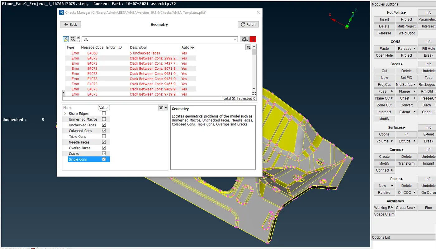
Figure. 2. Checks manager dialog box
Figure. 3. shows the Cleaned Geometry of the model using Checks manager dialog box.
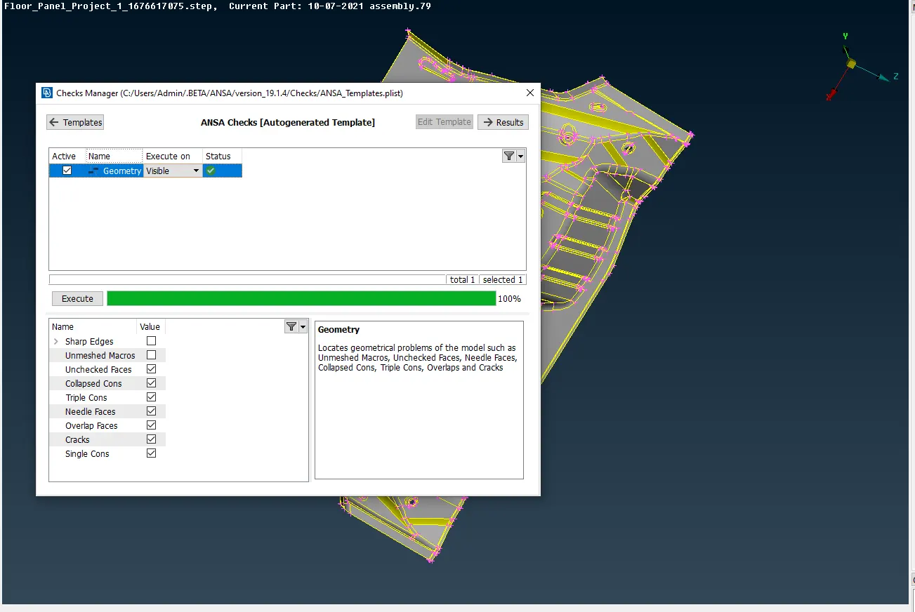
Figure. 3. Checks manager dialog box woth zero errors.
Mid – Surface Extraction
Manual mid surfaces are retrieved by selecting the faces of each component using the offset option and specifying the distance as half of the thickness or it is extracted using skin midsurface by
Command: Midsurface+ Skin.
as shown in Figure. 4. All the Mid – Surfaces are again checked for errors.
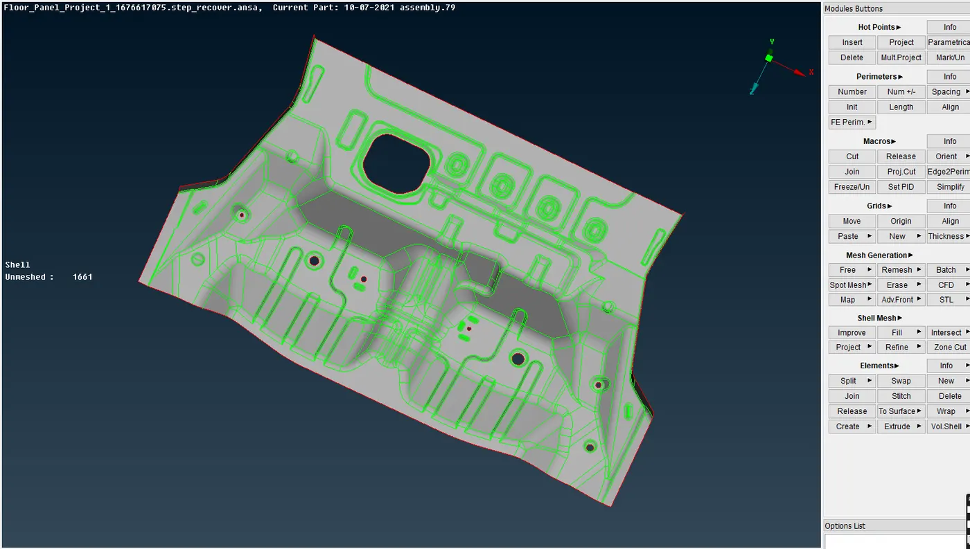
Figure. 4. Midsurface.
Quality Criteria
Figure. 5. shows the Quality Criteria for meshing
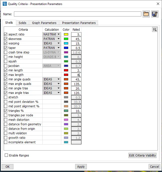
Figure. 4. Quality Criteria.
Meshing
Before meshing choose
Command: Perimeters + Length
then choose the entire component and give the target length of the mesh value as 5. Mesh is generated by
Command: Mesh Generation + Best Mesh
then choose the entire component for generation as shown in Figure. 5.
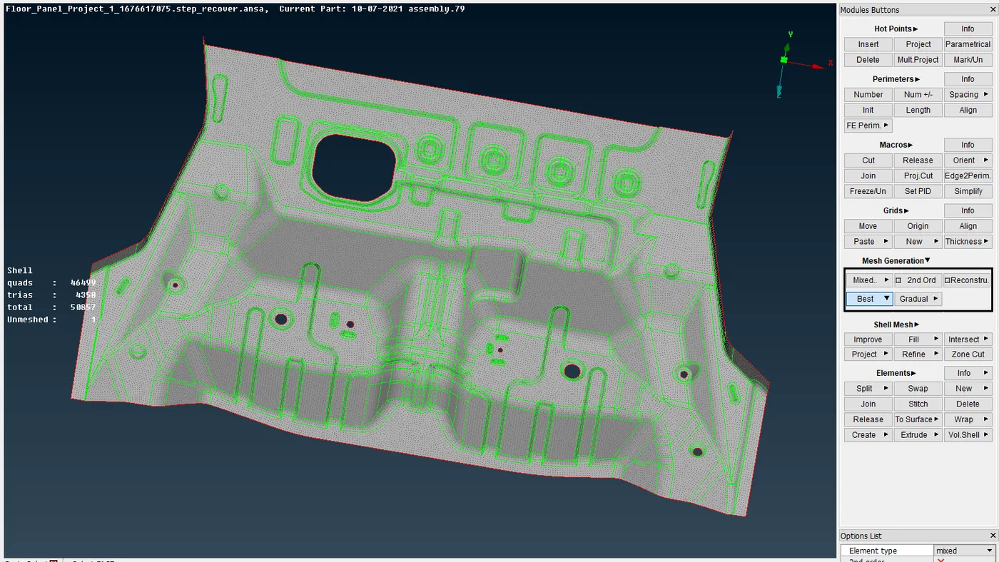
Figure. 5. Generated Mesh Elements.
To produce clean mesh flow with acceptable quality parameters manually with
Command: Elements + Split , Command: Elements + Swap, Command: Grids + Paste, Command: Elements + Join
For element editing and
Command: Shell mesh + Reconstruct and Command: Shell mesh + Smooth
For reconstructing and smooting the mesh and
Command: Shell mesh + Refine
For refining the mesh. the final mesh element is shown in Figure 6.
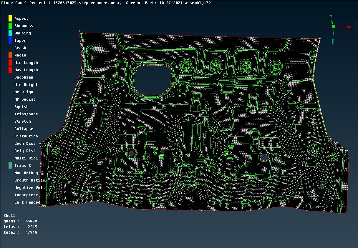
Figure. 6. Mesh Elements with Quality Criteria.
CONCLUSION :
The given Floor Panel Sheet Metal component successfully meshed and passed the geometrical errors with the given element Quality criteria.