Week 7- Meshing of Backdoor Challenge
Meshing of Backdoor Challenge
Objective:
To mesh the backdoor geometry of a car with provide quality parameters as follows
Target Element size - 5 Units
|
S.N |
Quality Criteria |
Value |
|
1 |
Aspect Ratio |
5 |
|
2 |
Skewness |
45 |
|
3 |
Warping |
15 |
|
4 |
Taper |
0.5 |
|
5 |
Min. Length |
3 Units |
|
6 |
Max. Length |
7 Units |
|
7 |
Min angle Quad |
45 |
|
8 |
Max angle Quad |
135 |
|
9 |
Min angle Tria |
30 |
|
10 |
Max angle Tria |
110 |
|
10 |
Tria % |
15 |
Procedures:
Geometry Import
The given the IGS file is Imported. After the geometry has been imported, the model is next processed for midsurface extraction after being checked for any missing surfaces or triple cons and the symmetry surfaces are deleted as shown in Figure 1.
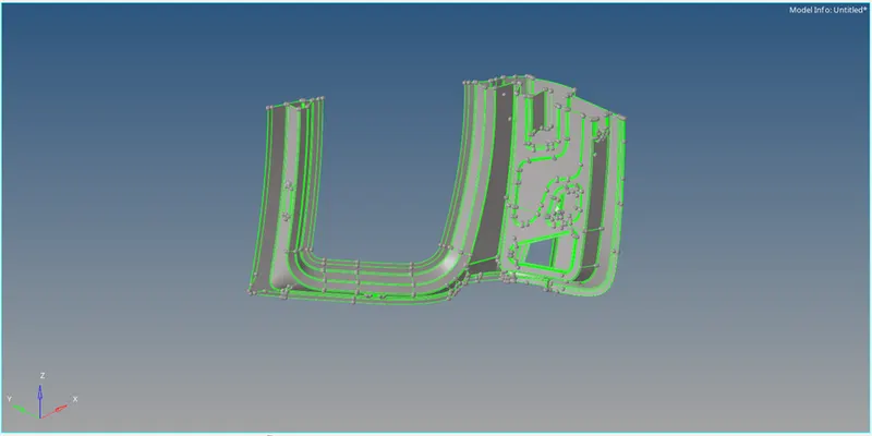
Figure 1: Backdoor model
Quality Criteria
The quality criteria has been assigned as per the given data by Preference + Criteria File Settings. In the Criteria Editor dialog box as shown in Figure 2.
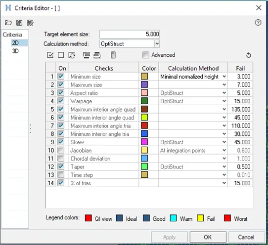
Figure 2: Criteria Editor dialog box
Extracted Midsurface
Midsurface can be extracted by Offset
Command: Geometry + Midsurface + Select Offset extraction option + select the surface + extract.
Geomentry Cleanup
Clean the geometry by the use of Quick edit option in the geometry. Use washer split, split surf-node, split surf-line, release point, project point, replace point, & toggle edge features for apt surface for mesh generation.
Component Mesh
Generate the mesh of element size as 5mm with mixed element type.
Command: 2D + Automesh + All Surface + Mixed element + Create
Mesh Quality
The meshed component is re meshed to avoid poor mesh elements with rebuild mesh option on localizied element selection.then with the help of Clean up tools the proper mesh quality is achieved, i.e. element optimize, place node, node optimize, split quad element, & drag tria element as shown in Figure 3,5&7.
Reflect Surface & Mesh elements
The backdoor Midsurface is obtained by reflect option in the tool and the surface is duplicated and then the duplicated surface is reflected in the Y-axis with a node from edge as the base. Full midsurface is shown in Figure 4,6&8.
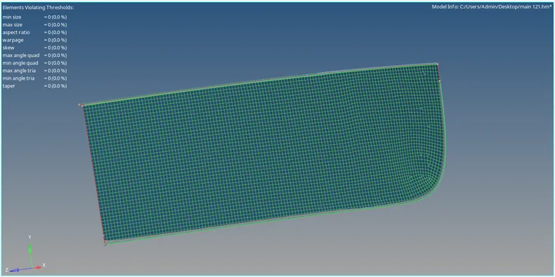
Figure 3: Segmented Midsurface with Mesh Quality
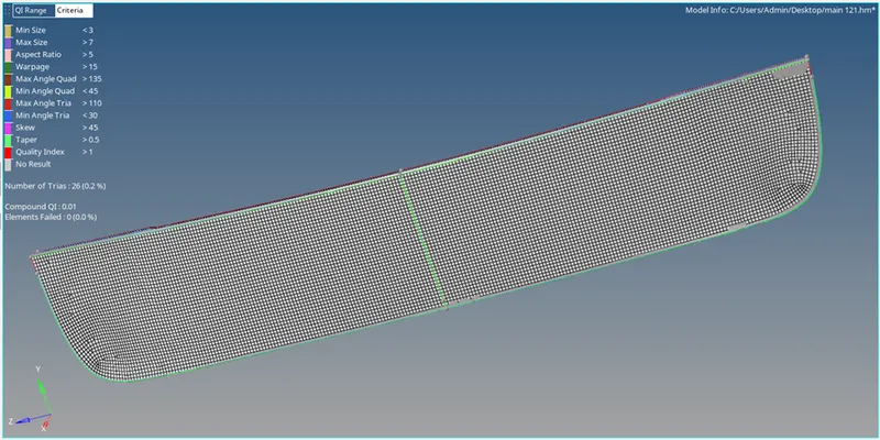
Figure 4: Reflected Midsurface & Mesh elements
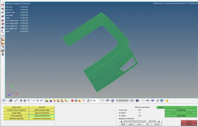
Figure 5: Segmented Midsurface with Mesh Quality
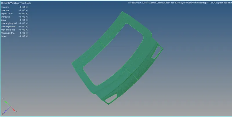
Figure 6: Reflected Midsurface & Mesh elements
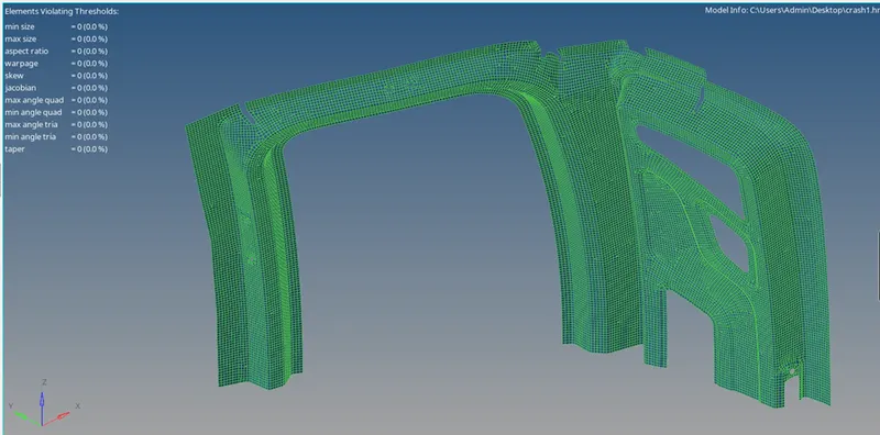
Figure 7: Segmented Midsurface with Mesh Quality
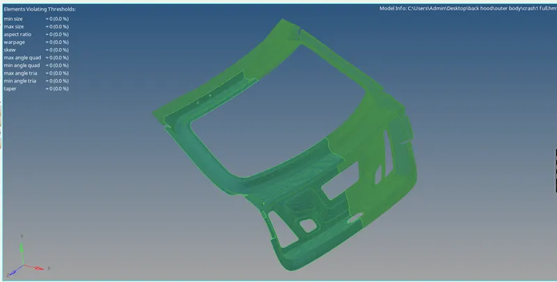
Figure 8: Reflected Midsurface & Mesh elements
Conclusion
Mid-surface is extracted from the provided Backdoorl, and mesh is created in accordance with the provided quality criteria.