Week 4 -Wire Bending Challenge
STATIC STRUCTURAL ANALYSIS ON WIRE BENDING
Objective
To perform an simulation of bending of a wire in ANSYS Workbench with three different material cases for wire
Case 1: Copper Alloy NL
Case 2: Aluminium Alloy NL
Case 3: Magnesium Alloy NL
To find out the equivalent stress and equivalent strain on the wire in all three cases and compare them.
Material data
Figure. 1 shows the structural steel's properties in Ansys Workbench engineering data. It was used as the wire bending model's material input expect the wire.
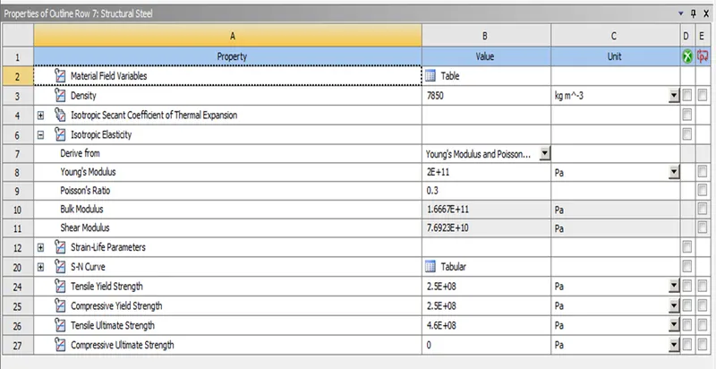
Figure. 1 Structural steel Engineering data.
Figure. 2 shows the Copper Alloy NL's properties in Ansys Workbench engineering data. It was used as the wire material input in Case 1.
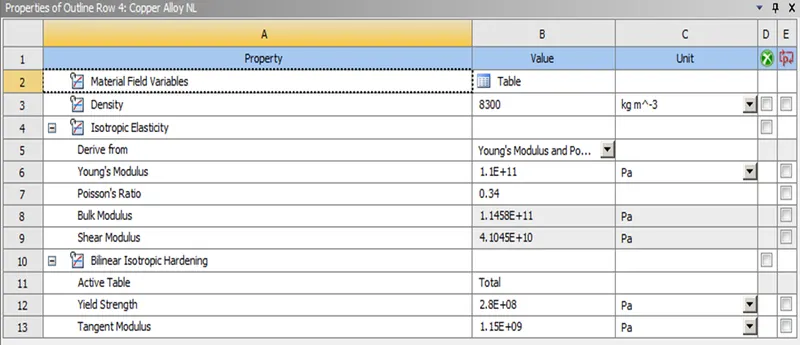
Figure. 2 Copper Alloy NL Engineering data.
Figure. 3 shows the Aluminium Alloy NL's properties in Ansys Workbench engineering data. It was used as the wire material input in Case 2.
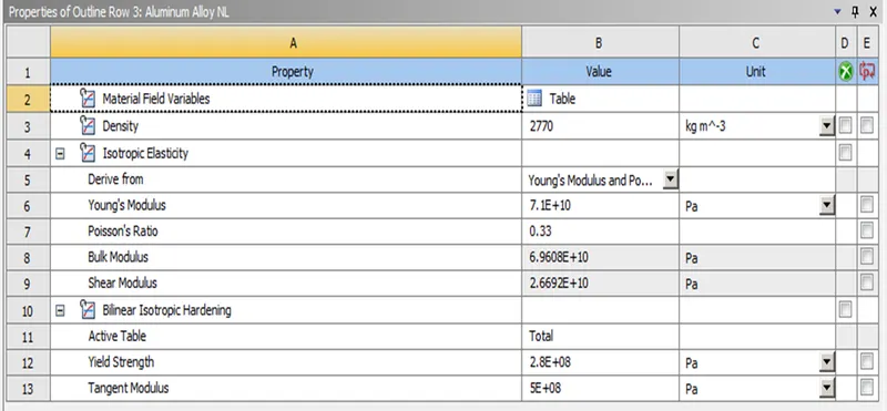
Figure. 3 Aluminium Alloy NL Engineering data.
Figure. 4 shows the Magnesium Alloy NL's properties in Ansys Workbench engineering data. It was used as the wire material input in Case 3.
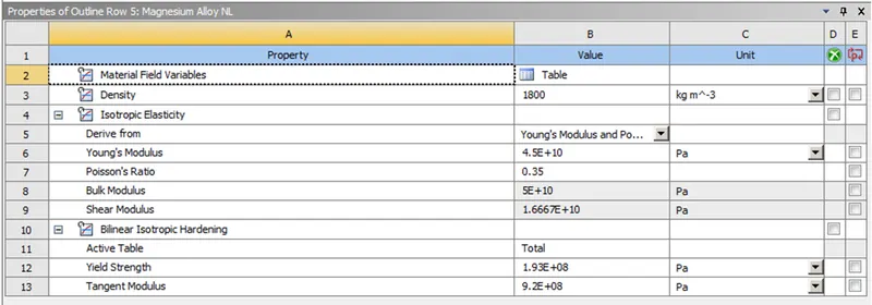
Figure. 4 Magnesium Alloy NL Engineering data.
Model Geomentry
Figure. 5 shows the imported given Wire Bending model in the mechanical modular.
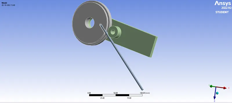
Figure. 5 Wire Bending model.
Connections
Initially the models are renamed as Wheel, Wire and Crank. Figure. 6 illustrates the contact and target faces of the Wire Bending model. In which the Wire is assigned as “Contact Bodies” and the Crank is assigned as “Target Bodies” and The conncetion is assigned as Frictional contact.
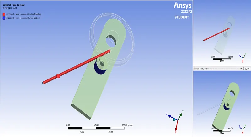
Figure. 6 Frictional-Wire to crank.
Figure. 7 illustrates the contact and target faces of the Wire Bending model. In which the Wheel is assigned as “Contact Bodies” and the Wire is assigned as “Target Bodies” and The conncetion is assigned as Frictional contact.
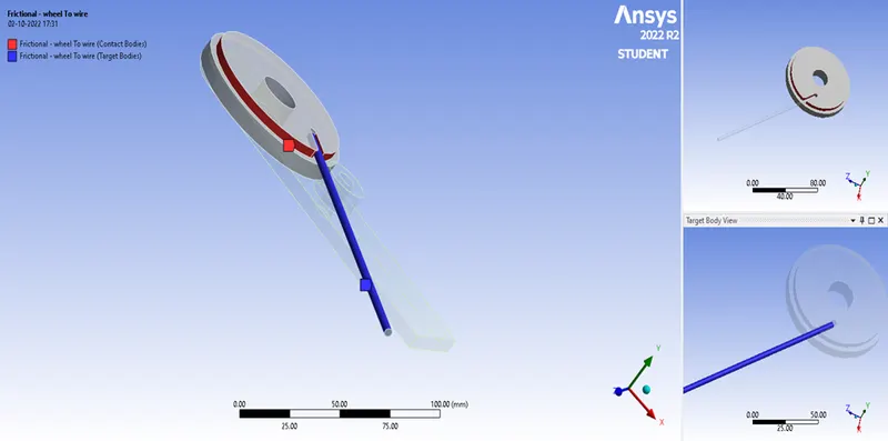
Figure. 7 Frictional-Wheel to Wire.
Meshing
Tetragonal meshing han been done in it with a default meshing and the wire and crank contact face was face sized with a mesh element size of 1.2mm. In order to refine the bending area face meshing with type as Sphere of influence of 7mm radius and mesh element size of 0.4mm was assigned, as shown in Figure. 8. The over all mesh was shown in Figure. 9.
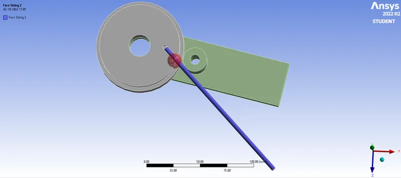
Figure. 8 Sphere of influence.
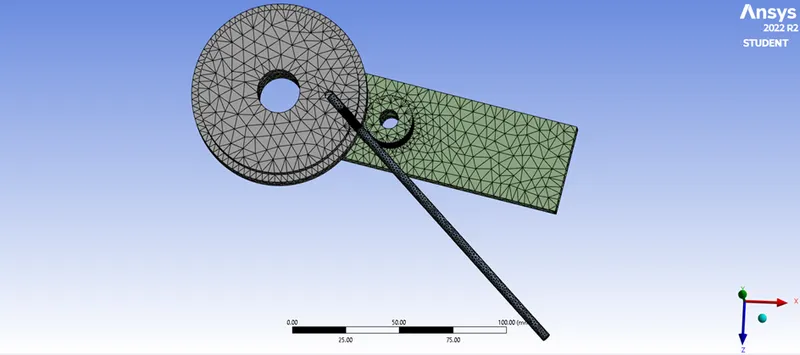
Figure. 9 Overall mesh of the model.
Fixed Joints
The Wheel is the stationary part in this model hence the inner face of the wheel was fixed and the face of wire inside the wheel is to be fixed to avoid sliping of the wire while bending. The two fixed supports are shown in Figure. 10 & Figure. 11.
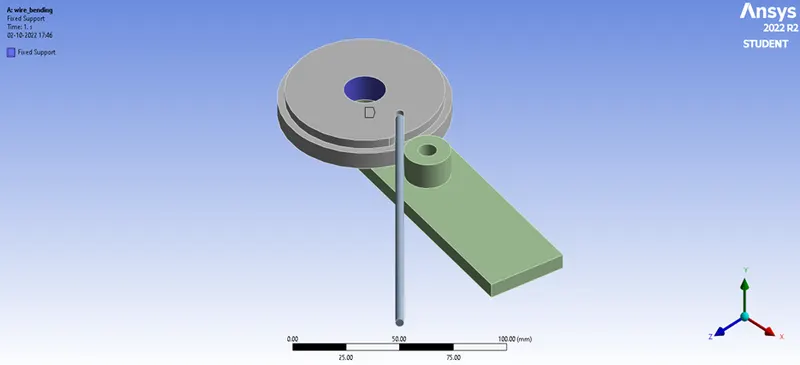
Figure. 10 Wheel Fixed Joint.
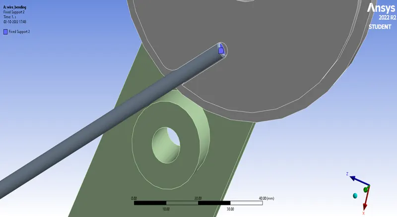
Figure. 11 Whire Fixed Joint.
Rotational Joint
The crank is to be rotated to 140o hence a rotational joint has been given to it since the 8 steps has been assigned in the analysis the rotation was increased by 20o in each steps. The rotational joint is shown in Figure. 12.
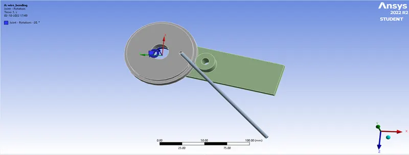
Figure. 12 Crank Rotational Joint.
Simulation Results
Case1
Equivalent Elastic Strain
Figure. 13 illustrates the Equivalent Elastic Strain of Copper Alloy NL material with the wire and the rest of the bodies will be structural steel material. Since the maximum and minimum Equivalent Elastic Strain was not in the wire, the individual maximum and minimum Equivalent Elastic Strain is shown in Figure. 14.
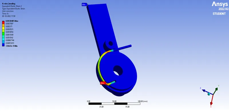
Figure. 13 Equivalent Elastic Strain of Wire Bending (Copper Alloy NL) with all bodies
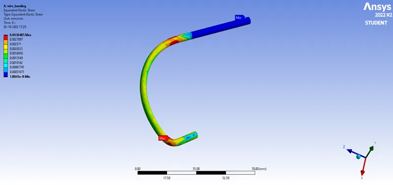
Figure. 14 Equivalent Elastic Strain of Wire Bending (Copper Alloy NL)
Equivalent Stress
Figure. 15 illustrates the Equivalent Stress of Copper Alloy NL material with the wire and the rest of the bodies will be structural steel material. Since the maximum and minimum Equivalent Stress was not in the Wire, the individual maximum and minimum Equivalent Stress is shown in Figure. 16.
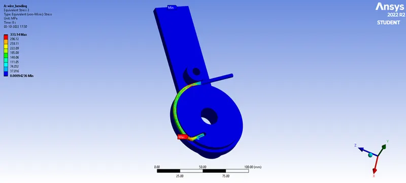
Figure. 15 Equivalent Stress of Wire Bending (Copper Alloy NL) with all bodies
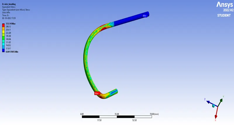
Figure. 16 Equivalent Stress of Wire Bending (Copper Alloy NL)
Total Deformation
Figure. 17 illustrates the Total Defprmation of Copper Alloy NL material with the wire and the rest of the bodies will be structural steel material. Since the maximum and minimum Total Deformation was not in the Wire, the individual maximum and minimum Total Deformation is shown in Figure. 16.
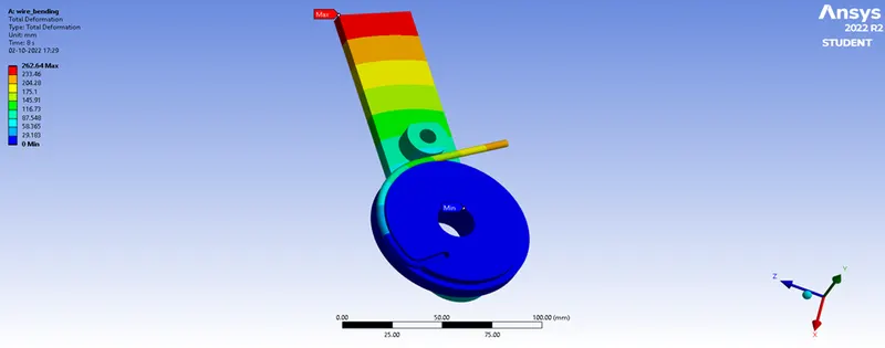
Figure. 17 Total Deformation of Wire Bending (Copper Alloy NL) with all bodies
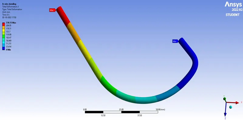
Figure. 18 Total Deformation of Wire Bending (Copper Alloy NL)
Case 2
Equivalent Elastic Strain
Figure. 19 illustrates the Equivalent Elastic Strain of Aluminium Alloy NL material with the wire and the rest of the bodies will be structural steel material. Since the maximum and minimum Equivalent Elastic Strain was not in the wire, the individual maximum and minimum Equivalent Elastic Strain is shown in Figure. 20.
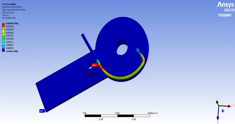
Figure. 19 Equivalent Elastic Strain of Wire Bending (Aluminium Alloy NL) with all bodies
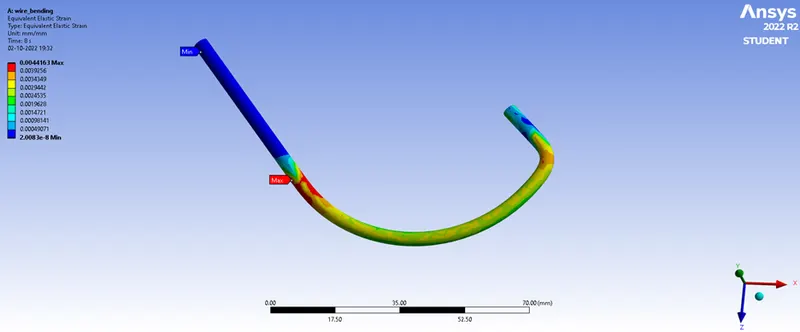
Figure. 20 Equivalent Elastic Strain of Wire Bending (Aluminium Alloy NL)
Equivalent Stress
Figure. 21 illustrates the Equivalent Stress of Aluminium Alloy NL material with the wire and the rest of the bodies will be structural steel material. Since the maximum and minimum Equivalent Stress was not in the Wire, the individual maximum and minimum Equivalent Stress is shown in Figure. 22.
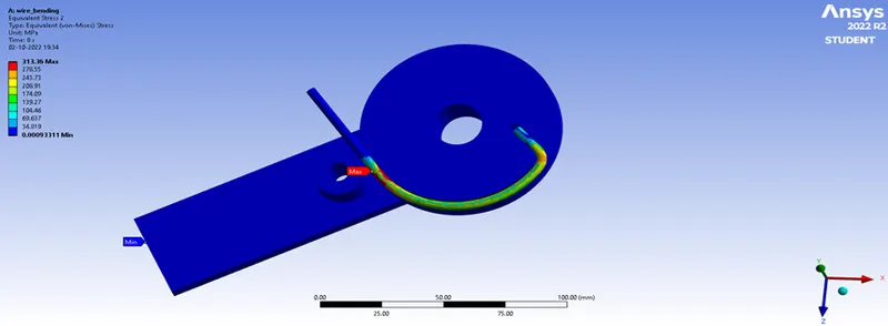
Figure. 21 Equivalent Stress of Wire Bending (Aluminium Alloy NL) with all bodies
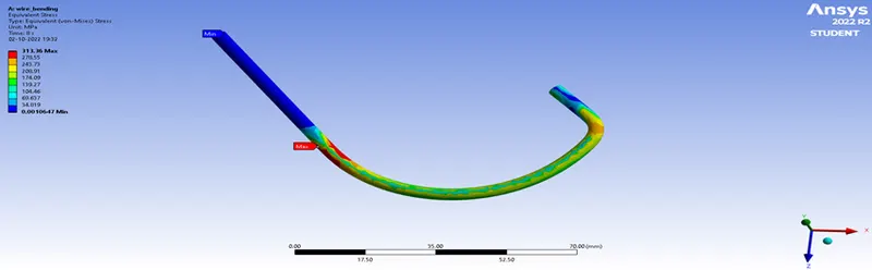
Figure. 22 Equivalent Stress of Wire Bending (Aluminium Alloy NL)
Total Deformation
Figure. 23 illustrates the Total Defprmation of Aluminium Alloy NL material with the wire and the rest of the bodies will be structural steel material. Since the maximum and minimum Total Deformation was not in the Wire, the individual maximum and minimum Total Deformation is shown in Figure. 24.
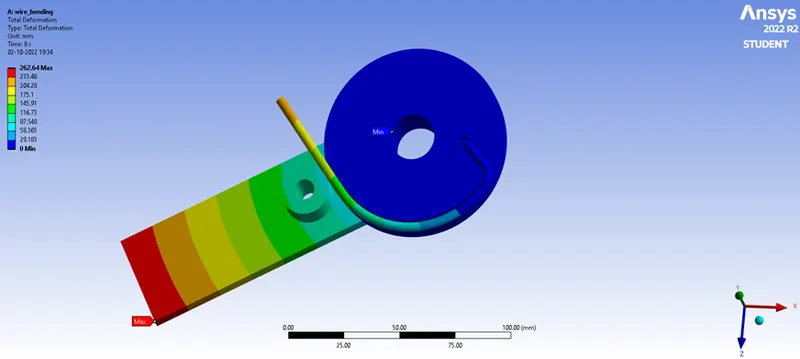
Figure. 23 Total Deformation of Wire Bending (Aluminium Alloy NL) with all bodies
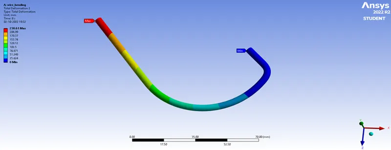
Figure. 24 Total Deformation of Wire Bending (Aluminium Alloy NL)
Case 3
Equivalent Elastic Strain
Figure. 25 illustrates the Equivalent Elastic Strain of Magnesium Alloy NL material with the wire and the rest of the bodies will be structural steel material. Since the maximum and minimum Equivalent Elastic Strain was not in the wire, the individual maximum and minimum Equivalent Elastic Strain is shown in Figure. 26.
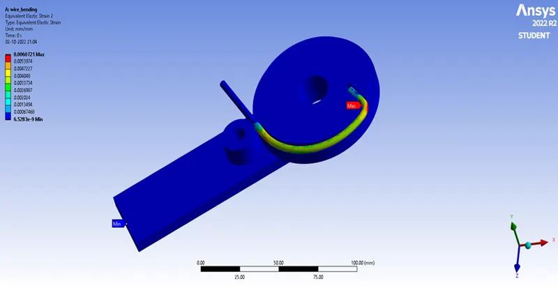
Figure. 25 Equivalent Elastic Strain of Wire Bending (Magnesium Alloy NL) with all bodies
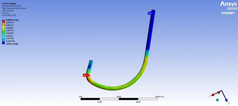
Figure. 26 Equivalent Elastic Strain of Wire Bending (Magnesium Alloy NL)
Equivalent Stress
Figure. 27 illustrates the Equivalent Stress of Magnesium Alloy NL material with the wire and the rest of the bodies will be structural steel material. Since the maximum and minimum Equivalent Stress was not in the Wire, the individual maximum and minimum Equivalent Stress is shown in Figure. 28.
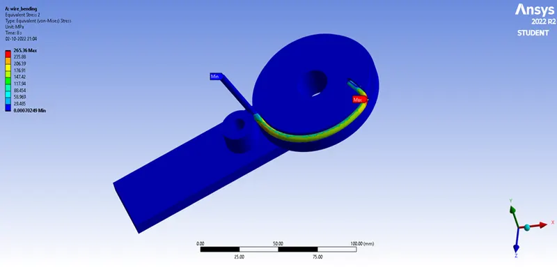
Figure. 27 Equivalent Stress of Wire Bending (Magnesium Alloy NL) with all bodies
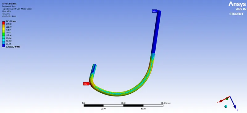
Figure. 28 Equivalent Stress of Wire Bending (Magnesium Alloy NL)
Total Deformation
Figure. 29 illustrates the Total Defprmation of Magnesium Alloy NL material with the wire and the rest of the bodies will be structural steel material. Since the maximum and minimum Total Deformation was not in the Wire, the individual maximum and minimum Total Deformation is shown in Figure. 30.
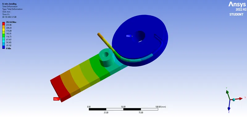
Figure. 29 Total Deformation of Wire Bending (Magnesium Alloy NL) with all bodies
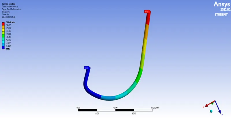
Figure. 30 Total Deformation of Wire Bending (Magnesium Alloy NL)
Comparison Of Case 1, Case 2 & Case 3
|
Wire Materials |
Parameters |
Maximum |
Minimum |
|
Copper Alloy NL |
Total Deformation |
230.55 mm |
0 mm |
|
Equivalent Stress |
333.14 Mpa |
0.00170 Mpa |
|
|
Equivalent Elastic Strain |
0.00304 mm |
1.8841e-8 mm |
|
|
Aluminium Alloy NL |
Total Deformation |
230.61 mm |
0 mm |
|
Equivalent Stress |
313.36 Mpa |
0.00106 Mpa |
|
|
Equivalent Elastic Strain |
0.00441 mm |
2.0083e-8 mm |
|
|
Magnesium Alloy NL |
Total Deformation |
230.48 mm |
0 mm |
|
Equivalent Stress |
265.36 MPa |
0.0007 MPa |
|
|
Equivalent Elastic Strain |
0.00607 mm |
2.0455e-8 mm |
Conclusion
- From the above comparison the total deformation was same (approximately) in all cases but Equivalent Stress and Equivalent Elastic Strain differs.
- Case 3 attains the least Maximum Equivalent Stress and Case 1 attains the highest and similarly for Minimum Equivalent Stress also. This was direct opposite in Equivalent Elastic Strain.
- Thus, a structural analyses of the provided wire that was bent was done. For wires made of several non-linear alloys of the metals copper, aluminium, and magnesium, the required outputs of stress and strain generated on the wire were obtained and compared.