Week 4-1D Element Creation Challenge
1D Element Creation Challenge
Objective:
To create 1D elements on the given component with given cross-section and DOF using Hypermesh
GIVEN:
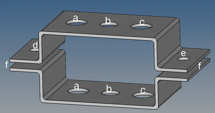
a. Rod element:- with only translational DOF and RBE2 link
Case 1:
Cross-Section: BOX- Dimension a= 12 mm
dimension b=10 mm
Thickness t= 0.75 mm
b. Beam element:- with all DOF and RBE3 link
Case 2:
Cross-Section: I Section- Dimension a= 8 mm
Dimension b= 10 mm
Dimension c= 8.5 mm
Thickness t1= 0.75 mm
Thickness t2= .6 mm
Thickness t3= .6 mm
c. Bar element:- with only x and y DOFs With RBE3 link
Case 3:
Cross-section: CROSS section- Dimension DIM1= 5 mm
Thickness DIM2= 1.2 mm
Dimension DIM3= 10 mm
Thickness DIM4= 1.2mm
d. & e. apply the mass of magnitude 10 with RBE2 link
f. Join the two components with Spring elements
Procedures:
Geometry Import
After importing the geometry into the workspace, delete the wireframe from the geometry.
Command: File+ Import + Geometry + IGS file + Import
Creating Component Midsurface
Create a mid surface for the component by choosing one component and rename it as bracket 1, so that the two midsurface will not get merge to a single midsurface.
Command: 1D + Midsurface + Auto Midsurface + select the surface + Create
Repeat the same step for the other component and create a mid surface then rename it as bracket 2.
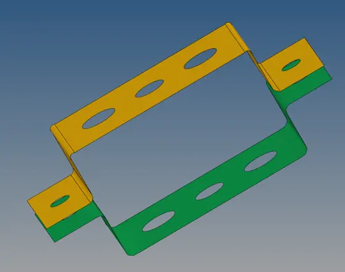
Figure 1: Midsurface of the components
Washer split should be done to get ordered mesh on the holes of the components.
Command: Geometry + Quick edits + Washer split
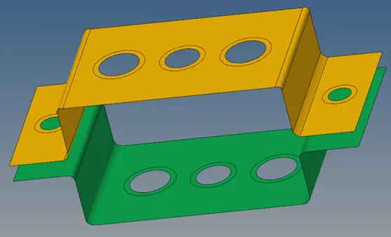
Figure 2: Midsurface with Washer split of the components
Create Material and Properties
Create a Material and name it as Steel and assign a card image of MAT1 to it. Create two Properties for bracket 1 and bracket 2 then assign the Steel material to both of them with PSHELL as image card.
Mesh the component
Generate the mesh with element size as 5mm with mixed element type.
Command: 1D + Automesh + All Surface + Mixed element + Create
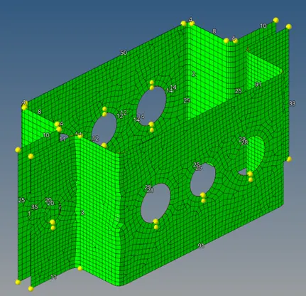
Figure 3: Meshed component
Create the RBE2 and RBE3 links at points a,b,c & d
RBE2 links is created using the Rigids in the 1D which is performed by selecting all the nodes on the hole along the surface path.
Command: 1D + Rigids + Calculate nodes + select the nodes from the surface + Create
RBE2 links is created using the rbe3 option in the 1D which is performed by selecting all the nodes on the hole along the surface path.
Command: 1D + rbe3 + Calculate nodes + select the nodes from the surface + Create
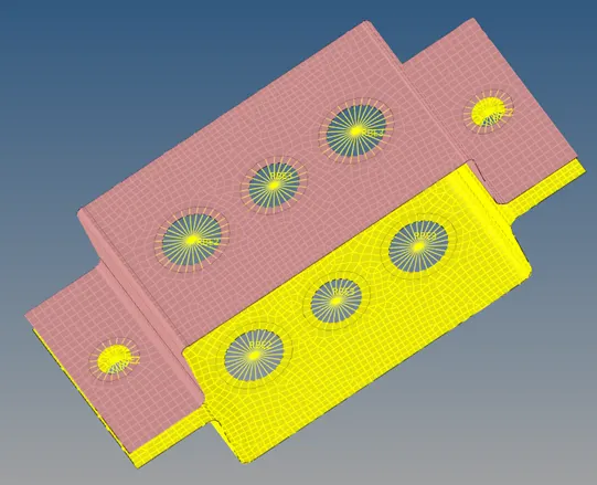
Figure 4: RBE2 and RBE3 linked component
Create the 1D Elements
To create cross sections for Rod, Bar & Beam
Create
- cross sections for rod in the form of thin wall box which has been given for case 1.
- cross section for beam in the form of I-section which has been given for the case 2.
- cross sections for bar in the form of Cross-section which has been given for the case 3.
- Command: 1D + Hyperbeam + Standard section + Hyperbeam + thin wall box + Create
Same command for other two, instead of box, I-section & Cross-section will be selected respectively.
Then create property for all three cases and give card image as PROD for case 1, PBAR for case 2 &3.
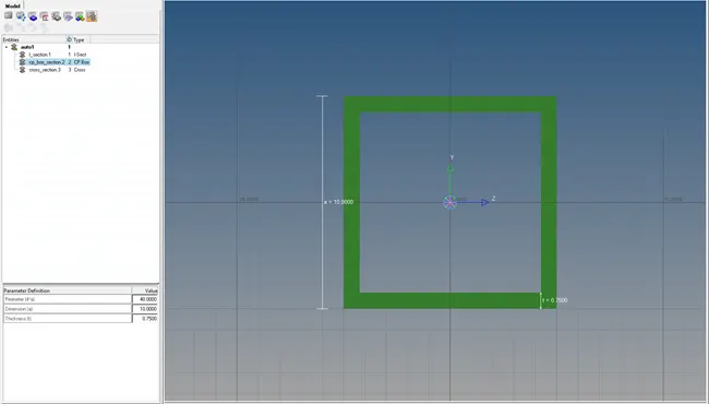
Figure 5: Box
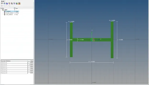
Figure 6: I section
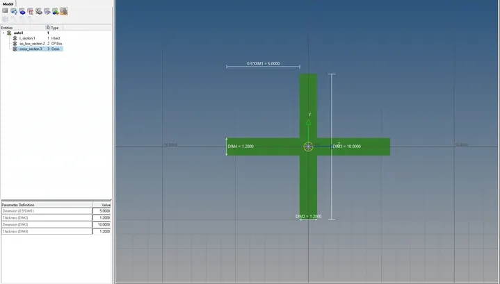
Figure 7: CROSS section
Create the 1D element on the RBE2 and RBE3 links and apply mass to RBE2 links
Constructing the 1D rod, bar, and beam components at the appropriate node locations, Update the 1D element with respect to their property. Get the mass at node d and insert the spring in between two brackets.
Command: 1D + bars + select the nodes from the surface + element type: CROD + Create
Same command for other two, instead of CROD, CBAR will be selected respectively.
Then update the property and select 1D Detailed Element Representation to get the cross section.
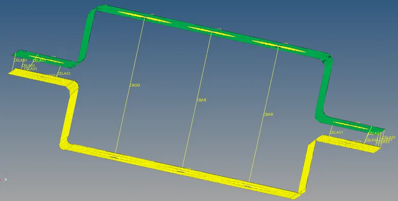
Figure 8: Rod, Bar and Beam representation before property update
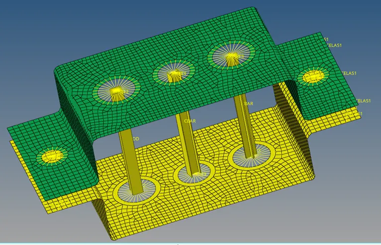
Figure 9: Rod, Bar and Beam representation after property update
Conclusion
- The model has been imported, and mid-surface have been extracted from the components then material property are assigned.
- A appropriate 1D element (RBE2, RBE3, ROD, BAR, BEAM, MASS, SPRING, etc.) was deployed to the appropriate locations.
- Created the cross sections for Rod, Beam, Bar, and assigned the Propertiey CardsPROD, PBEAM, and PBAR to them.
- Solid representations of 1D elements were produced.