Project 2 - 2D meshing on the instrumental Panel
Project 2 - 2D meshing on the instrumental Panel
Objective:
To check the geometry and obtain the mid surface then mesh the given instrumental panel with the given quality criteria and assign thickness for the model.
Given quality criteria:
|
S.No |
Quality Criteria |
Value |
|
1 |
Target/Average length |
4 |
|
2 |
Minimum Length |
2 |
|
3 |
Maximum Length |
6 |
|
4 |
Aspect |
3 |
|
5 |
Warpage |
15 |
|
6 |
Skewness |
45 |
|
7 |
Jacobian |
0.7 |
|
8 |
Minimum Quad Angle |
45 |
|
9 |
Maximum Quad Angle |
135 |
|
10 |
Minimum Tria Angle |
30 |
|
11 |
Maximum Tria Angle |
120 |
|
10 |
Tria Percentage |
15 |
Procedure:
Imported model
Figure. 1 shows the imported instrumental panel model in ANSA
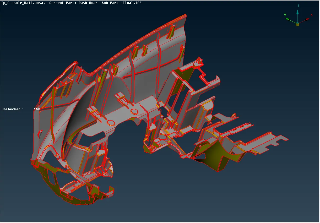
Figure. 1. Imported instrumental Panel model
Geometry Clean-up
The next essential stage is checking the model's geometry. This will assist us in eliminating all surface errors, undesirable Cons, as well as any disruptions made to the model. this is done by
Command: Tools+Checks + Geometry.
For the Checks Manager dialog box as shown in Figure. 2. Total Errors can be cleared automatically by
Command: Right-click + Fix.
In the Checks Manager dialog box. Errors can be cleared manually by
Command: Faces+Delete / New, Command: Faces+ Topo, Command: Faces+ Orient.
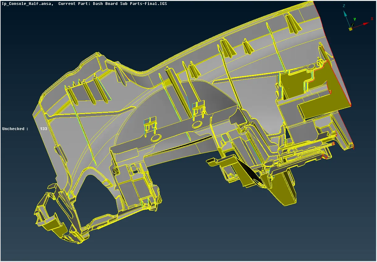
Figure 2: Model after Command: Faces+ Topo
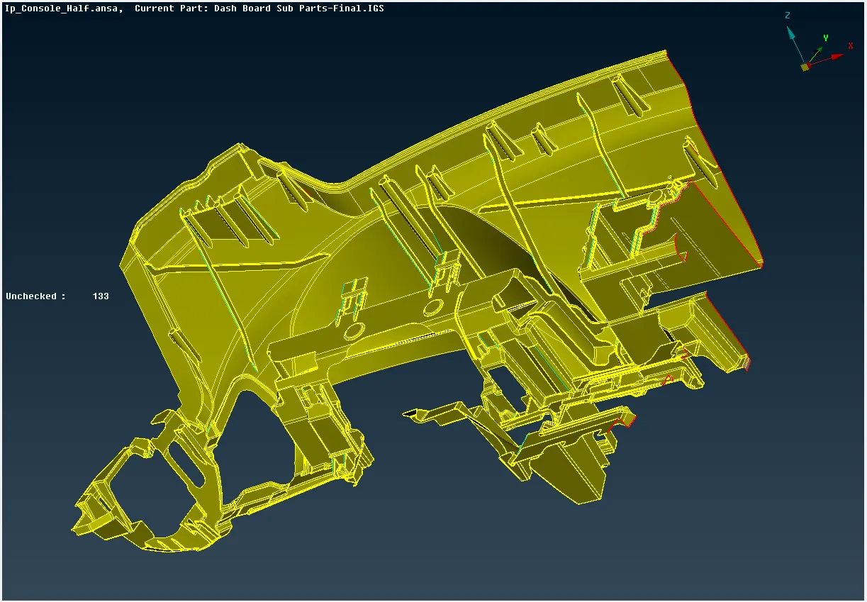
Figure 3: Model after Command: Faces+ Orient
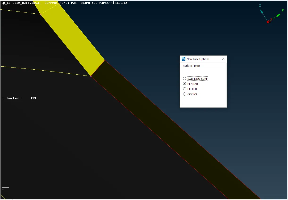
Figure 4: Model while new faces, Command: Faces+ New
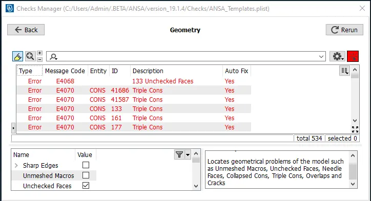
Figure. 5. Checks manager dialog box
Figure. 6. shows the Cleaned Geometry of the model using the Checks Manager dialog box.
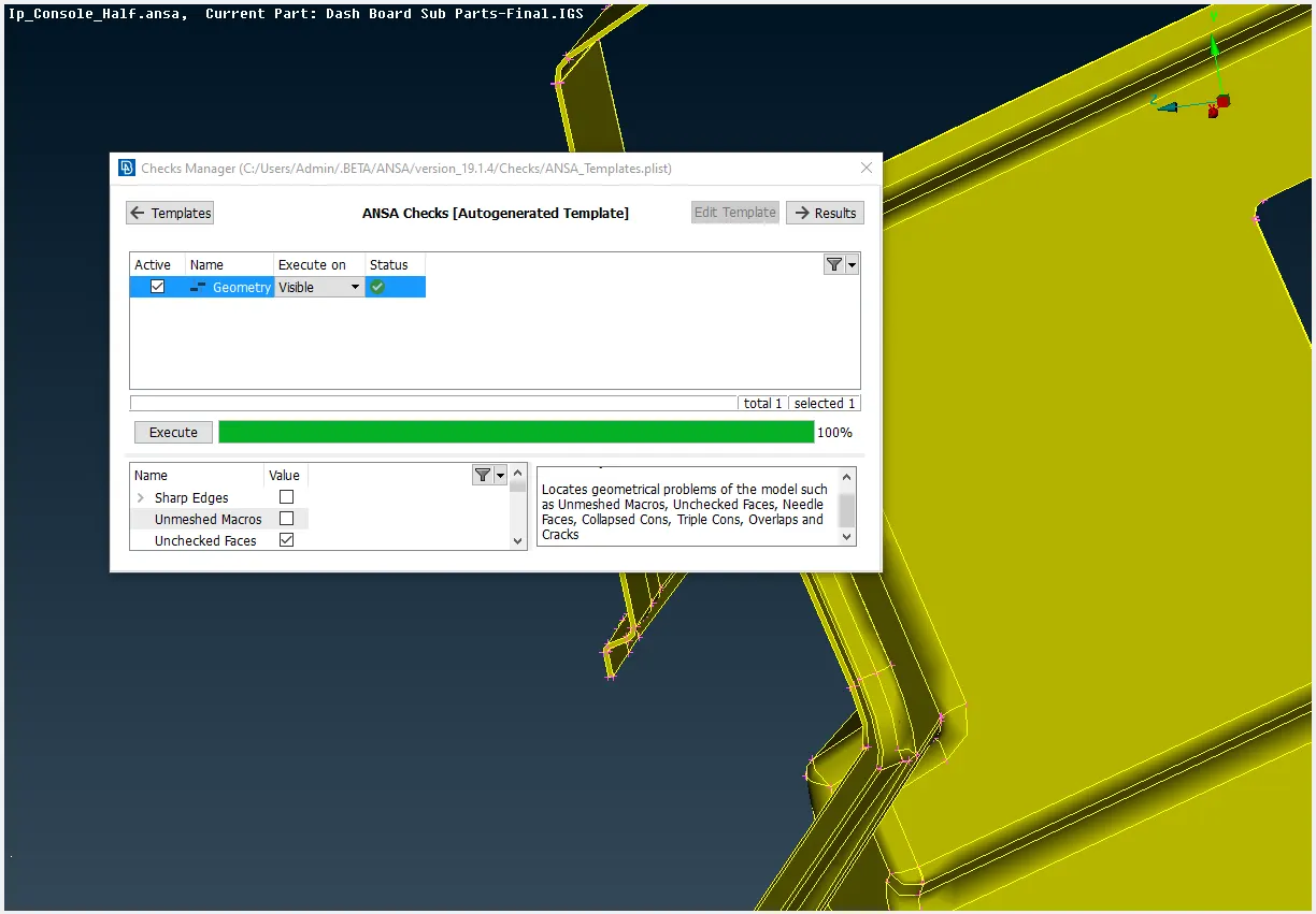
Figure. 6. Checks manager dialog box with zero errors.
Midsurface
To extract the midsurface by the following commands.
For two surfaces with equal thickness.
Command: Faces+Offset
Figure 5. shows the top body upper body
For varying thickness
Command: Faces + Middle + (single or multi).
For irregular quadrilateral (Such as threads and trapezoid)
Command: Curve+middle (To get mid curve of the threads).
Command: Cons+Project (To project the midcurve to midsurface).
Command: Faces+New (To create new surface).
Figure 7. shows the instrumental Panel Mid- surface
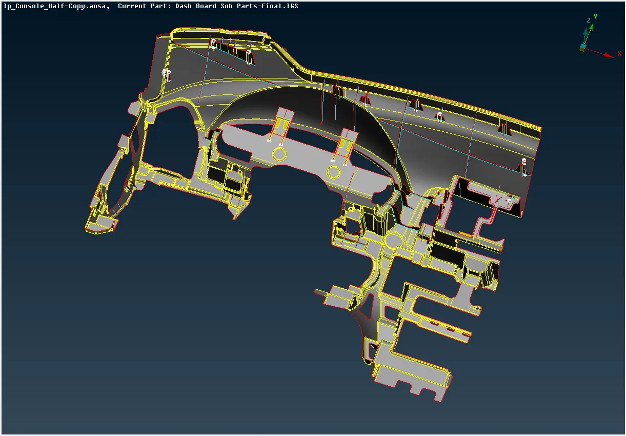
Figure 7. Instrumental Panel Mid- surface
Assigning Thickness
The midsurface thickness to be assigned. Since we have some surfaces with different thicknesses, we must gradually alter the thickness under each surface by the
Command: Property+New+Pshell+Assign thickness+Assign name.
Figure 8. shows the properties dialogue box
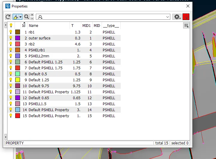
Figure 8. Properties dialogue box
Quality Criteria
Assign quality criteria for the mesh by clicking quality criteria tab then assign values in ths shells by checking the given parameters as per given data. Figure. 9. shows the Quality criteria dialoge box
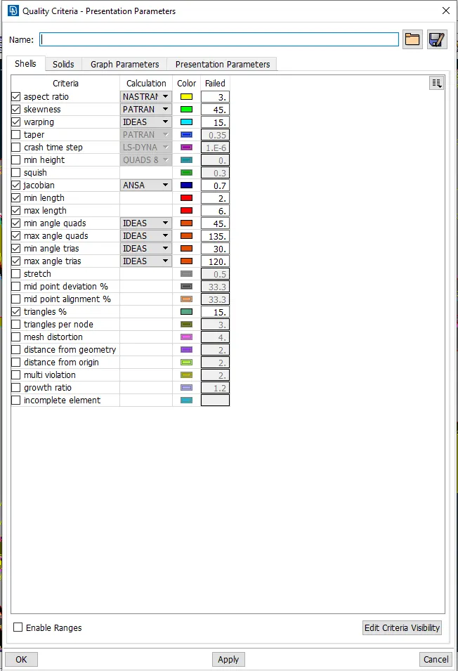
Figure. 9. The Quality criteria dialog box
Meshing
Before mesh generation assign peremeter lenght by
Command: Mesh +Perimeter + Length
Figure 10. shows the length parameters dialogbox
For Meshing select best mesh in the mesh generation using the
Command: Mesh generation+Best
The mesh will be generated and it should be reconstructed with
Command: Shell mesh+Reconstruct
To get quality mesh and to reduce tria elements by the following commands.
For element spliting
Command: Element + Split.
For element sjoining
Command: Element + Join.
For element refining
Command: Shell Mesh+Refine
Figure 11. shows the meshed model with nill off
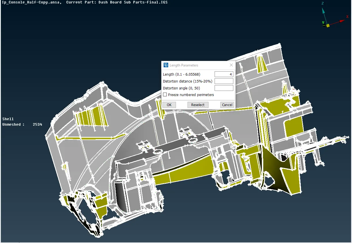
Figure 10. Length parameters dialog box
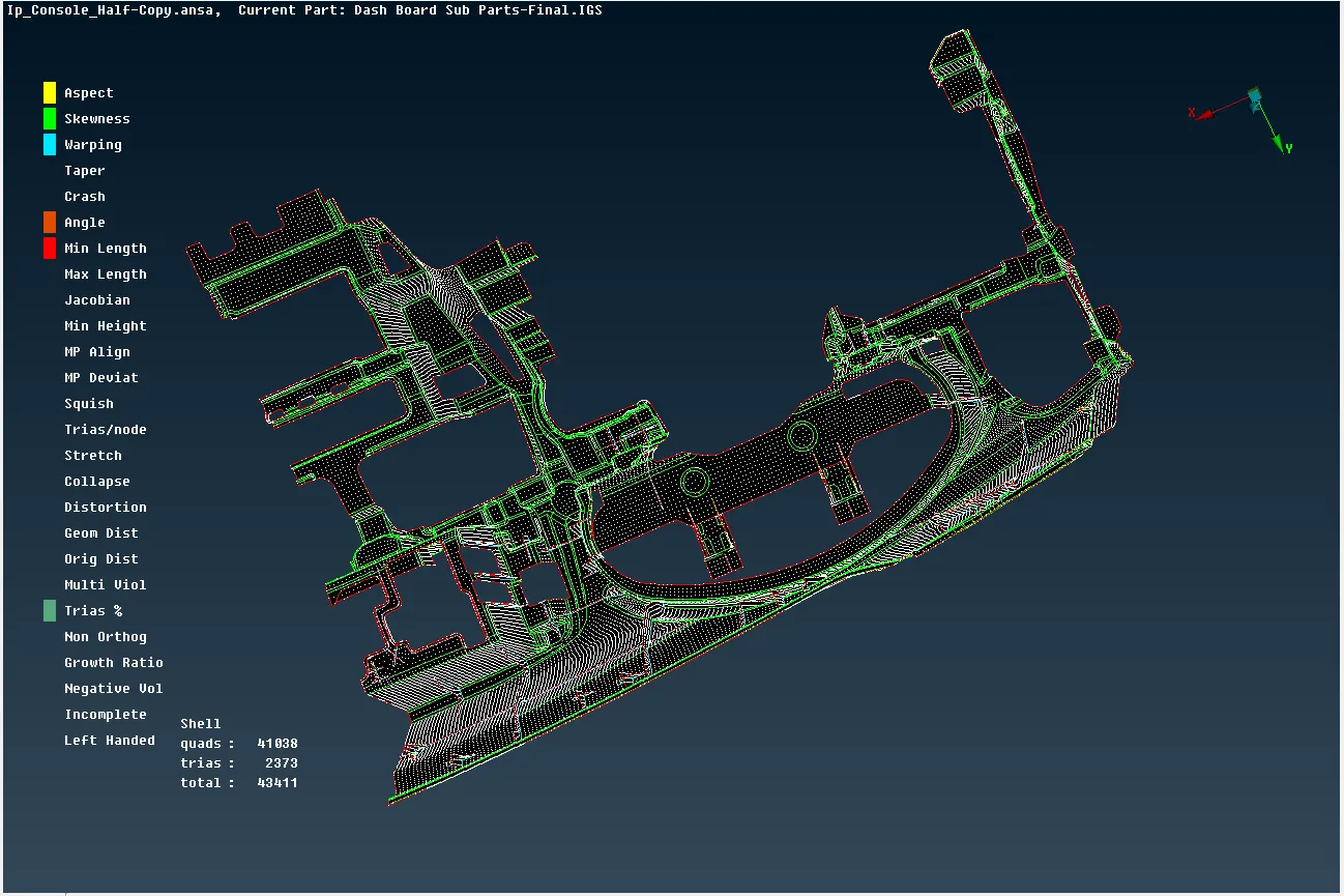
Figure 11. Meshed Model
After completion of meshing, use Quality Criteria dialoge box in the Presentation Parameters check the Draw Shell as Solid as shown in Figure. 12.
Using this option allows us to view all elements as solid or in three dimensions.
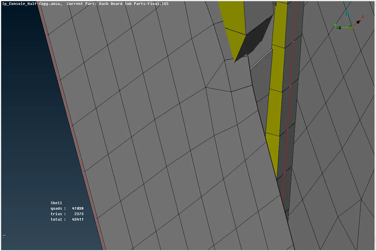
Figure. 12. Checking the Draw Shell as Solid
2D mesh will be displayed as solid mesh according to given thickness of each midsurface as in Figure. 13.
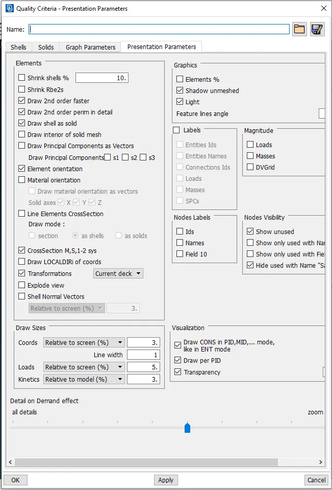
Figure. 13. Solid Meshed Elements
Conclusion
Various surface thicknesses are allocated and a midsurface is utilized to mesh the provided instrumental Panel model with the quality criteria.