Week 12-Creation of 1D Connectors Challenge
Creation of 1D Connectors Challenge
Objective:
To mesh the given geometry and assign given quality parameters
The given Quality Criteria
Target Element size - 5 Units
|
S.N |
Quality Criteria |
Value |
|
1 |
Aspect Ratio |
5 |
|
2 |
Skewness |
45 |
|
3 |
Warping |
15 |
|
4 |
Taper |
0.5 |
|
5 |
Min. Length |
2 Units |
|
6 |
Max. Length |
8 Units |
|
7 |
Min angle Quad |
45 |
|
8 |
Max angle Quad |
135 |
|
9 |
Min angle Tria |
30 |
|
10 |
Max angle Tria |
110 |
|
10 |
Tria % |
15 |
Then to create a connector and Attach the various parts of the given model
- Right_Rail_2 & Front_truss_1:- Seam-Quad(angled+capped+L)
- Left_Rail_2 & Front_truss_1:- Quad elements
- Front_truss_2, Front_truss_1 & Right_Rail_1:- Spot weld with 2 Layers and 5 mm Diameter
- Front_truss_2, Front_truss_1 & Left_Rail_1:- Hexa (Adhesive)
- Rear_truss_2 & Right_Rail_2:- Bolt Connector
- Rear_truss_2 & Left_Rail_2:- Bolt Connector
- Right_Rail_1 & Right_Rail_2:- Spot-weld with Rigid Elements
- Left_Rail_1 & Left_Rail_2:- Spot-weld with Spring Elements
- Rest all the components left Join them with suitable connectors
Procedures:
Geometry Import & meshing
The given the .iges file is Imported. The imported model is a surface component hence the model is next processed for 2d meshing as shown in Figure 1.
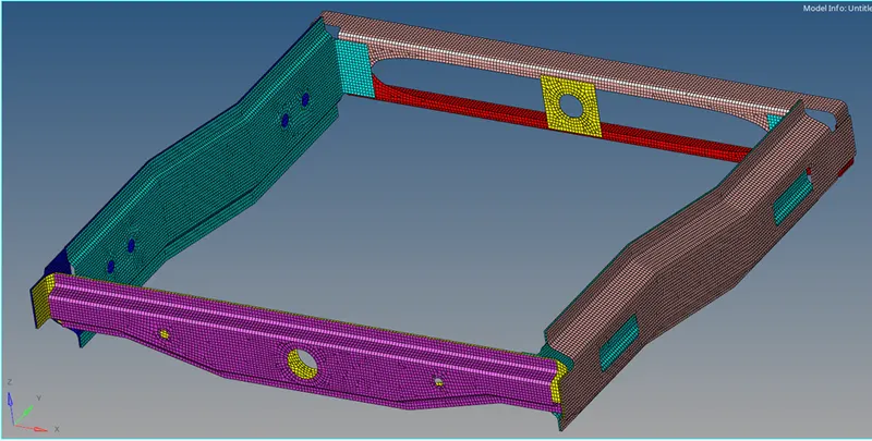
Figure 1: Meshed model
Quality Criteria
The quality criteria has been assigned as per the given data by Preference + Criteria File Settings. In the Criteria Editor dialog box as shown in Figure 2.
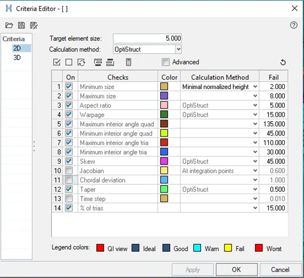
Figure 2: Criteria Editor dialog box
- To Create Seam-Quad(angled+capped+L) connector for Right_Rail_2 & Front_truss_1
- The Seam-Quad(angled+capped+L) connector is created by
Command: 2D+ Connectors+ seam+ location: nodelist (by path)+ components+ weld type: seam-quad (angled+capped+L)+ create
- While performing the command adapt the following parameters :
- tolerance = 10mm, ( Specify the search distance )
- keep the imprint check on
- The spacing = 5mm and the weld angle = 45 is which is based on alignment of two components.
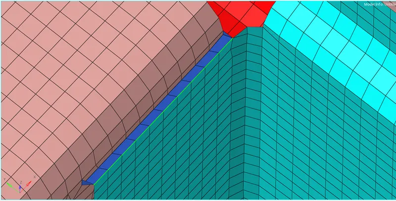
Figure 3: Seam-Quad(angled+capped+L) connector
- To Create Seam- Quad elements connector for Left_Rail_2 & Front_truss_1
- The seam weld: Connectors is created by
Command: 2D+ Connectors+ seam+ location: nodelist (by path)+ components+ weld type: quads+ create
- While performing the command adapt the following parameters :
- tolerance = 10mm, ( Specify the search distance )
- keep the imprint check on
- The spacing = 5mm (distance between the two adjacent weld elements)
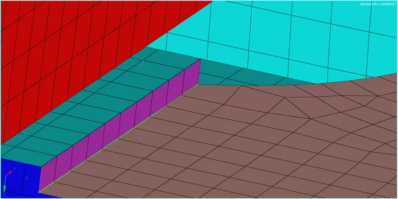
Figure 4: Seam- Quad elements connector
- To Create Spot weld with 2 Layers and 5 mm Diameter for Front_truss_2, Front_truss_1 & Right_Rail_1
- The spot weld is created by
Command: 2D+ connectors+ spot+ location: nodes (by path)+ components+ type:weld+ create
- While performing the command adapt the following parameters :
- Diameter = 5mm and number of layers as 2.
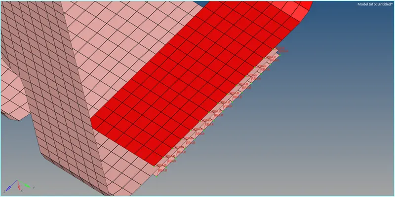
Figure 5: Spot weld with 2 Layers and 5 mm Diameter
- To Create Hexa (Adhesive) for Front_truss_2, Front_truss_1 & Left_Rail_1
- Hexa (Adhesive) is created by
Command: 2D+ connectors+ seam+ location: nodes lists(by path)+ components+ type:hexa (Adhesive)+ create
- While performing the command adapt the following parameters :
- tolerance = 10mm, ( Specify the search distance )
- keep the imprint check on
- The spacing = 5mm (distance between the two adjacent weld elements)
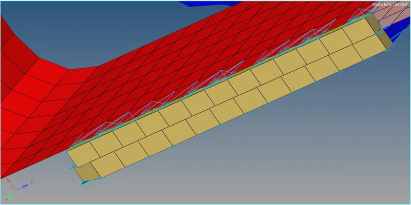
Figure 6: Hexa (Adhesive) connector
5.To Create Bolt Connector for Rear_truss_2 & Right_Rail_2
- bolt connector is created by
Command: 2D+ connectors+ bolt+ location: nodes (by path)+ components+ type:bolt (general)+ create
- While performing the command adapt the following parameters :
- number of layers as 2.
- tolerance = 10mm, ( Specify the search distance )
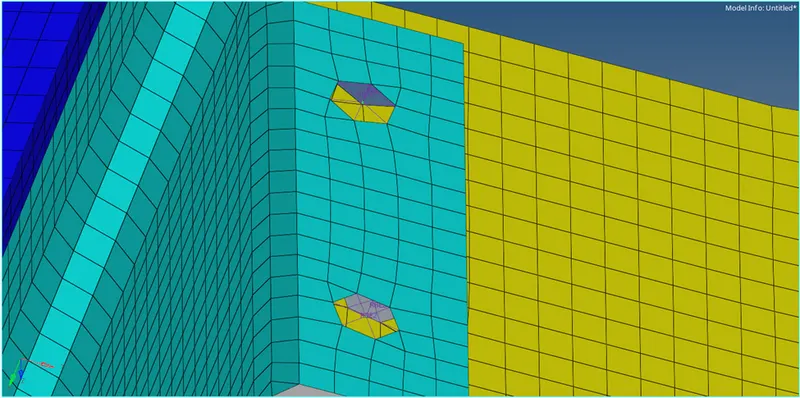
Figure 7: bolt connector_1
6.To Create Bolt Connector for Rear_truss_2 & Left_Rail_2
Followed the same procedure from bolt connector_1
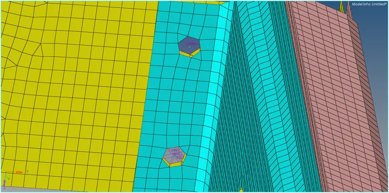
Figure 8: bolt connector_2
- To Create Spot-weld with Rigid Elements for Right_Rail_1 & Right_Rail_2
- Similar to how spot welds were previously constructed, this spot weld is made using rigids rather than weld in the weld type as shown in figure 9.
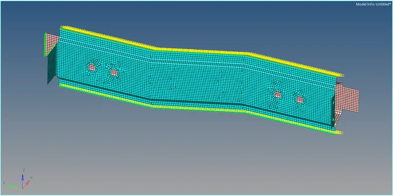
Figure 9: Spot-weld with Rigid Elements
- To Create Spot-weld with Spring Elements for Left_Rail_1 & Left_Rail_2
- Similar to how spot welds were previously constructed, this spot weld is made using spring rather than weld in the weld type as shown in figure 10.
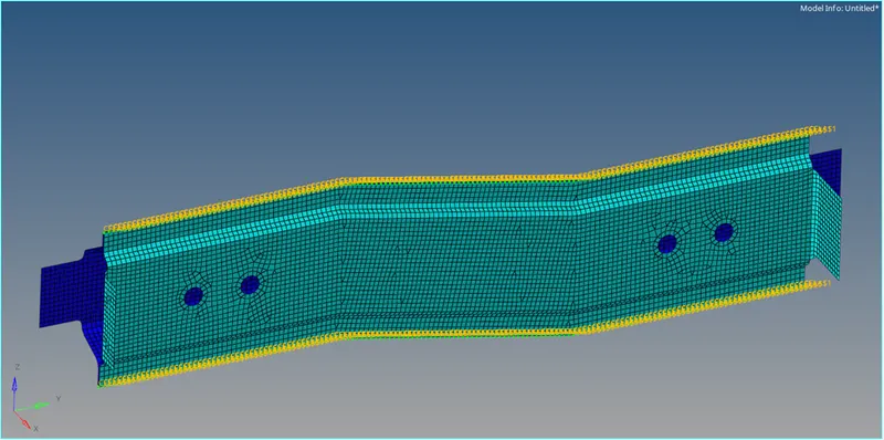
Figure 10: Spot-weld with Spring Elements
- For other components
The other components are connected by Seam- Quad elements and Spot-weld with Rigid Elements as shown in figure 11& 12
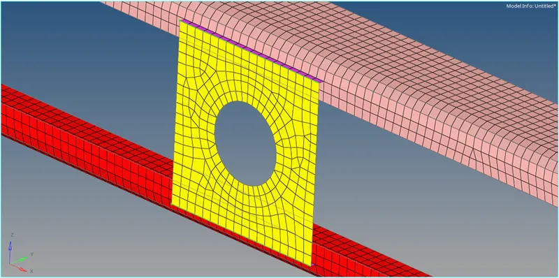
Figure 11: Seam- Quad elements connector for hole component
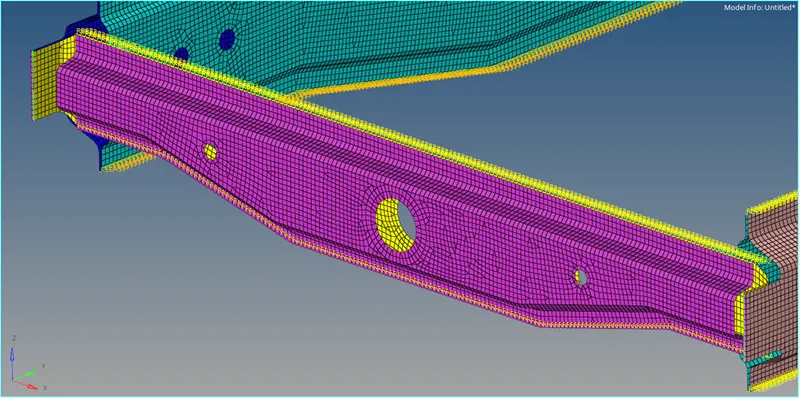
Figure 12: Spot-weld with Rigid Elements connector for rail elements
The final fully connected elements is shoen in figure 12.
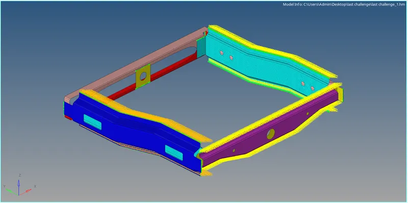
Figure 13: final fully connected model.
Conclusion
As a result, all the parts have been integrated and the necessary connections have been identified and successfully implemented.