Week 4- Rolling operation
STATIC STRUCTURAL ANALYSIS ON ROLLING OPERATION
Objective
- To perform a static structural analysis and to Simulate the rolling operation on a workpiece made of copper for 14 steps and to ensure that the edge of the workpiece is displaced by 90mm.
- To find out
- Equivalent stress for the whole setup
- Equivalent Plastic strain for the workpiece
- Directional Deformation in the Z axis for the workpiece
- To Prove that the workpiece had displaced by 90mm.
Material data
Figure. 1 shows the structural steel's properties in Ansys Workbench engineering data. It was used as the rolling operation model's material input expect the workpiece.
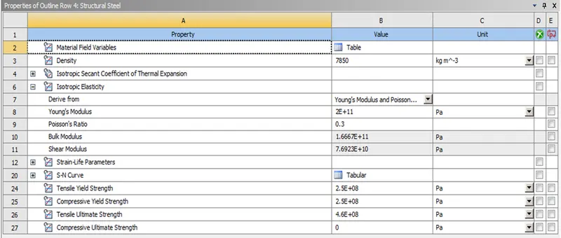
Figure. 1 Structural steel Engineering data.
Figure. 2 shows the Copper Alloy NL's properties in Ansys Workbench engineering data. It was used as the workpiece material input.
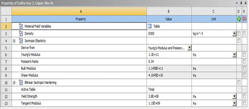
Figure. 2 Copper Alloy NL Engineering data.
SpaceClaim Model
Figure. 3 shows the given rolling operation model
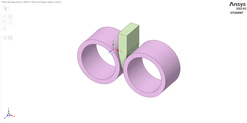
Figure. 3 Given rolling operation model
Figure. 4 shows the Edited model with increased length of the workpiece by 60mm and decreased size on both sides by 8mm.
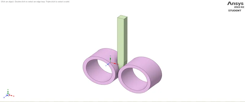
Figure. 4 Edited rolling operation model
Model Geomentry
Figure. 5 shows the imported given rolling operation model in the mechanical modular.
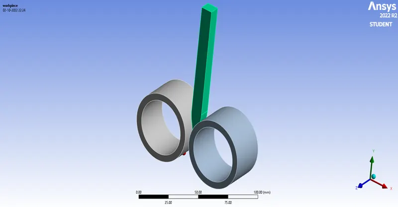
Figure. 5 Rolling operation model in mechanical modular
Connections
Initially the models are renamed as Wheel 1, Wheel 2 and Workpiece. Figure. 6 illustrates the contact and target faces of the Rolling operation model. In which the Workpiece faces is assigned as “Contact Bodies” and the Wheel 1 is assigned as “Target Bodies” and The conncetion is assigned as Frictional contact.
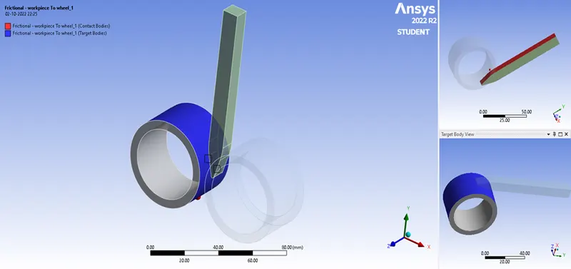
Figure. 6 Frictional-Workpiece toWheel_1.
Figure. 7 illustrates the contact and target faces of the Rolling operation model. In which the Workpiece faces is assigned as “Contact Bodies” and the Wheel 2 is assigned as “Target Bodies” and The conncetion is assigned as Frictional contact.
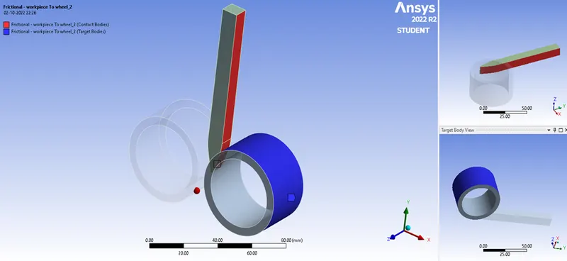
Figure. 7 Frictional-Workpiece toWheel_2.
Cylindrical Joints
Figure. 8 illustrates the Cylindrical Joint of the wheel 1 and Figure. 9 illustrates the Cylindrical Joint of the wheel 2.
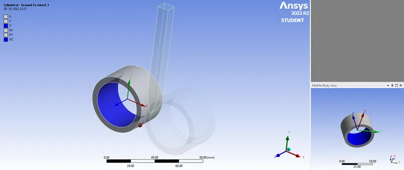
Figure. 8 Cylindrical Joint of the wheel 1
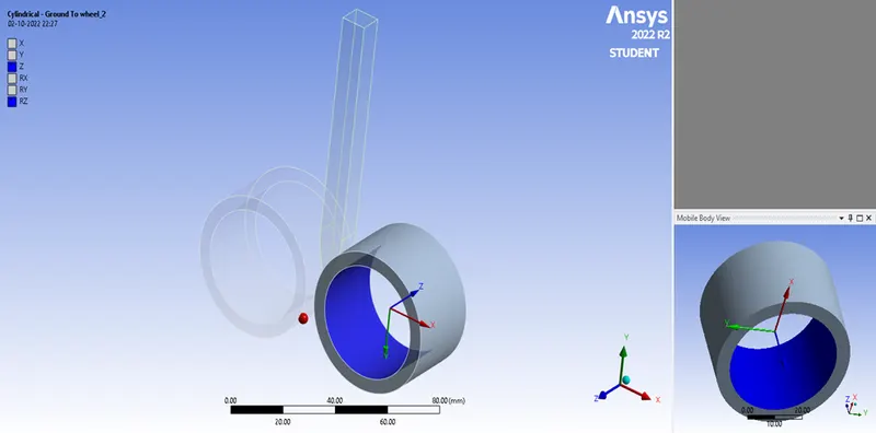
Figure. 9 Cylindrical Joint of the wheel 2
Meshing
The whole model is initially default meshed then the workpiece body is meshed with a body sizing if 3 mm as shown in Figure. 10.
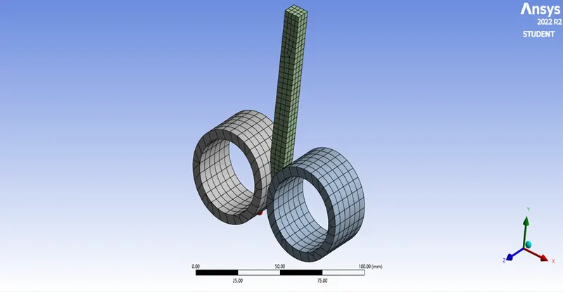
Figure. 10 Meshed Rolling operation model
Joint Rotation and Plate Displacement
The workpiece is ment to displace in the negative Y axis with 90mm displacement hence the two perpendicular faces of the workpiece is assigned with displacement joint as shown in Figure. 11 and the wheels rotations are ment to be 180o hence both the wheels are assigned with in the 14 steps as per the analysis setting. Joint Rotation of both the wheels are shown in Figure. 12.
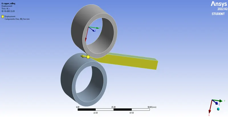
Figure. 11 Displacement Joint of the workpiece
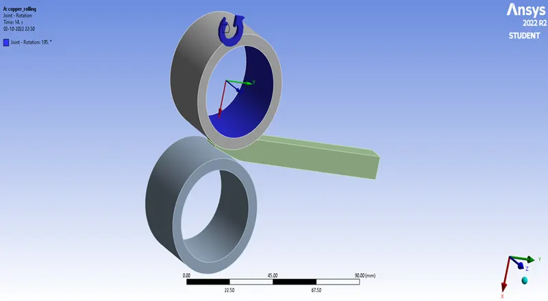
Figure. 12(a) Joint Rotation of the Wheel_1
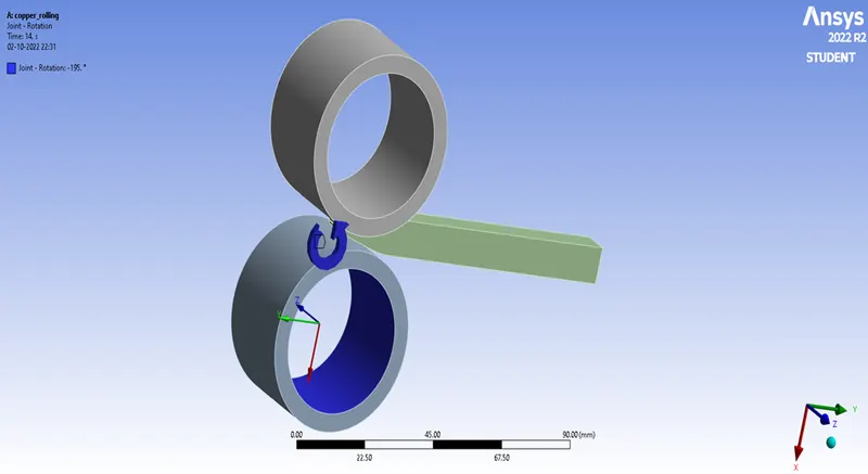
Figure. 12(b) Joint Rotation of the Wheel_2
Simulation results
Findout 1
Figure. 13 shows the Equivalent stress for the whole setup
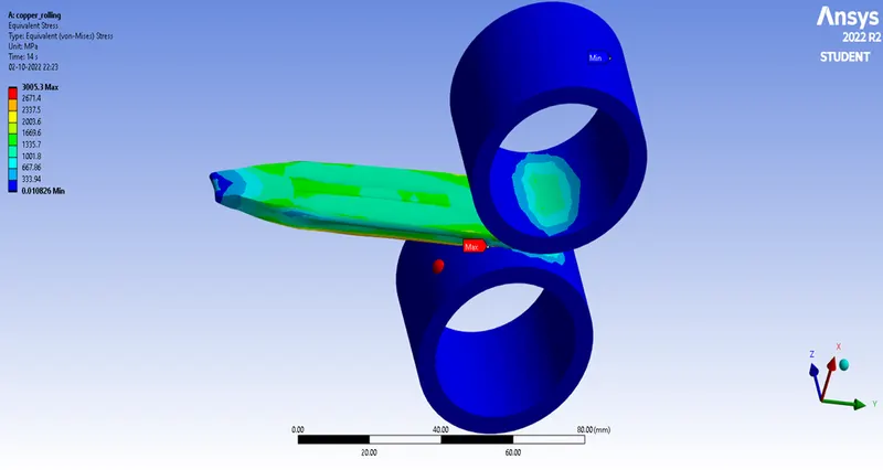
Figure. 13 Equivalent stress for the whole setup
Findout 2
Figure. 14 shows the Equivalent Plastic strain for the workpiece
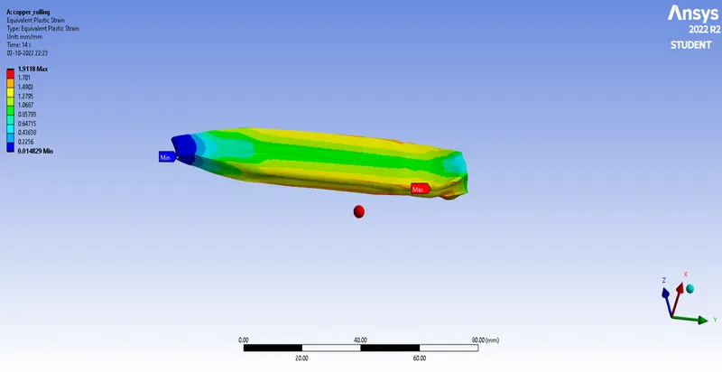
Figure. 14 Equivalent Plastic strain for the workpiece
Findout 3
Figure. 15 shows the Directional Deformation in the Z axis for the workpiece
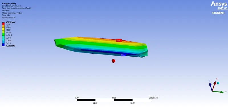
Figure. 15 Directional Deformation in the Z axis for the workpiece
Findout 4
Figure. 16 shows the assigned values for the displacement of workpiece in Z axis with in the 14 number of steps on Analysis setting. Hence displacement by 90mm is proved.
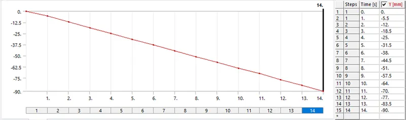
Figure. 16 Assigned values for the displacement of workpiece in Z axis
|
Parameters |
Values |
|
Maximum Equivalent stress (whole setup) |
3005.3 Mpa |
|
Maximum Equivalent Plastic strain |
1.9118 mm |
|
Maximum Directional Deformation |
6.5636 mm |
Conclusion
It can be conclude from the above result that Copper is experiencing an equivalent stress of 3005.3 Mpa. The workpiece's displacement of 90 mm is shown by adding a random value to the displacement, which is shown up to 90 mm in the Analysis setting value assignment. The workpiece's displacement of 90 mm also is shown by directional deformation, as shown in the above figure.