Week 8 - Universal Joint
Transient structural Analysis of Universal Joint
Objective
To perform a Transient Structural Simulation of Double Universal Joint mechanism with three different materials for only joint with spring part of the model and the three material cases,they are
Case 1: Structural Steel for joint with spring part of the model
Case 2: Stainless Steel for joint with spring part of the model
Case 3: Titanium alloy for joint with spring part of the model
To Find & Deliver
- Total deformation, equivalent stress all the three cases and compare them
Material data
Figure. 1 shows the Structural steel's properties in Ansys Workbench engineering data. It was used as the Universal Joint model's material input as per Case 1.
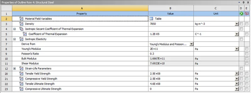
Figure. 1 Structural steel Engineering data.
Figure. 2 shows the Stainless steel's properties in Ansys Workbench engineering data. It was used as the Universal Joint model's material input as per Case 2.
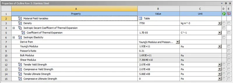
Figure. 2 Stainless steel Engineering data.
Figure. 3 shows the Titanium alloy's properties in Ansys Workbench engineering data. It was used as the Universal Joint model's material input as per Case 3.
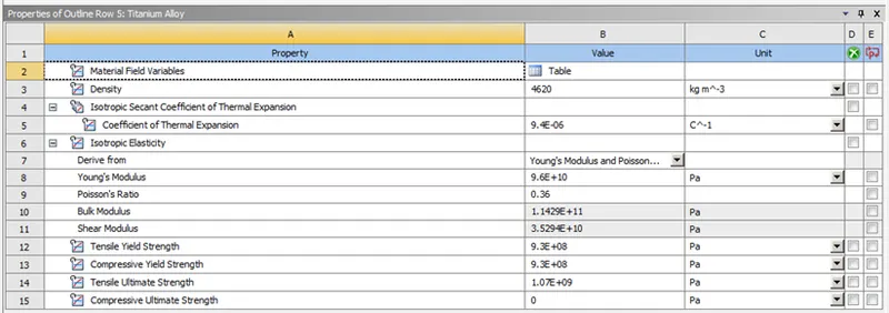
Figure. 3 Titanium alloy Engineering data.
Model Geomentry
Figure. 4 shows the imported given Universal Joint model in the mechanical modular.
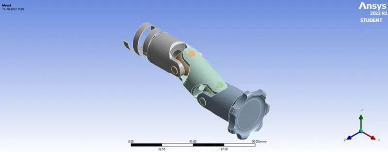
Figure. 4 Universal Joint model
Meshing
Figure. 5 illustrates The model is Default meshed with active Adaptive sizing and medium smoothing quality
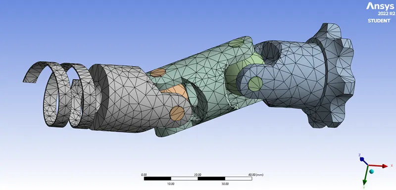
Figure. 5 Overall meshed model
Fixed and Revolute Joints
Figure. 6 illustrates Revolute Joint at the outer cylinderical face of Joint with gear in which rotational input will act, Figure. 7 illustrates Revolute Joint at the outer cylinderical face of Joint with spring in which the rotation will act respective to Joint with gear rotation and Figure. 8 illustrates Fixed Joint at the end face of the Spring.
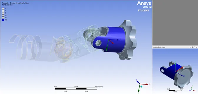
Figure. 6 Revolute - Ground To joint with Gear
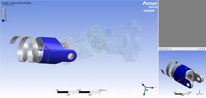
Figure. 7 Revolute - Ground To joint with Spring
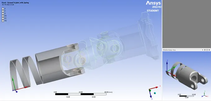
Figure. 8 Fixed - Ground To joint with Spring
Pin joints
Figure. 9 illustrates the Revolute joint at the left hole inner face of the Joint with Gear part which is assigned as the Mobile body with respective to assigned Reference body Pin joint 1 and Figure. 10 illustrates the Revolute joint at the Right hole inner face of the Joint with Gear part which is assigned as the Mobile body with respective to assigned Reference body Pin joint 1.
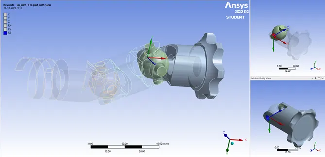
Figure. 9 Revolute - Pin joint 1 To joint with Gear ( Left hole )
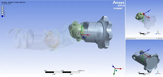
Figure. 10 Revolute - Pin joint 1 To joint with Gear ( Right hole )
Figure. 11 illustrates the Revolute joint at the bottom hole inner face of the Joint at Middle part which is assigned as the Mobile body with respective to assigned Reference body Pin joint 1, Figure. 12 illustrates the Revolute joint at the Top hole inner face of the Joint with Gear part which is assigned as the Mobile body with respective to assigned Reference body Pin joint 1
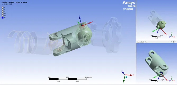
Figure. 11 Revolute - Pin joint 1 To joint at Middle (Bottom hole)
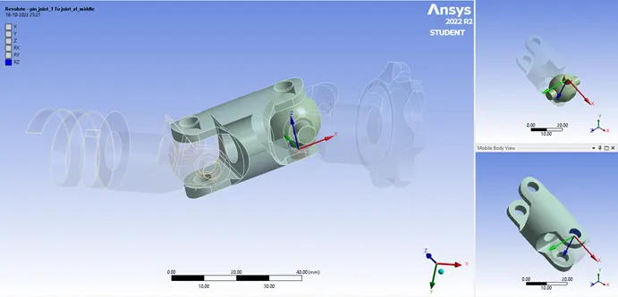
Figure. 12 Revolute - Pin joint 1 To joint at Middle (Top hole)
Figure. 13 illustrates the Revolute joint at the Top hole inner face of the Joint at Middle part which is assigned as the Mobile body with respective to assigned Reference body Pin joint 2, Figure. 14 illustrates the Revolute joint at the Bottom hole inner face of the Joint at Middle part which is assigned as the Mobile body with respective to assigned Reference body Pin joint 2.
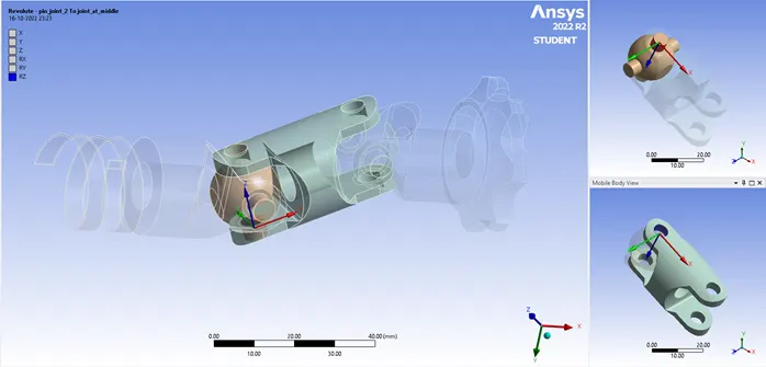
Figure. 13 Revolute - Pin joint 2 To joint at Middle (Top hole)
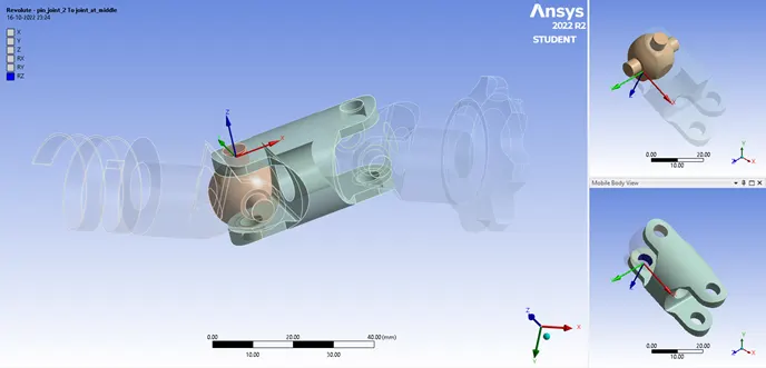
Figure. 14 Revolute - Pin joint 2 To joint at Middle (Bottom hole)
Figure. 15 illustrates the Revolute joint at the right hole inner face of the Joint with Spring part which is assigned as the Mobile body with respective to assigned Reference body Pin joint 2 and Figure. 16 illustrates the Revolute joint at the left hole inner face of the Joint with Spring part which is assigned as the Mobile body with respective to assigned Reference body Pin joint 2.
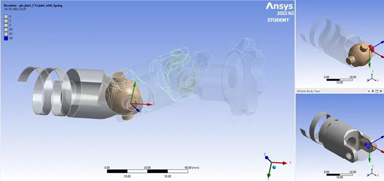
Figure. 15 Revolute - Pin joint 2 To joint with Spring ( Right hole )
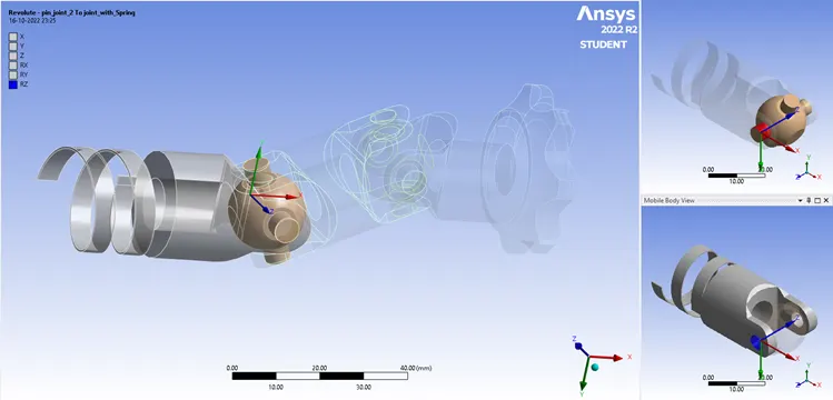
Figure. 16 Revolute - Pin joint 2 To joint with Spring ( Left hole )
Joint Rotation
Figure. 17 illustrates The Joint Rotation on the outer surface of the Joint with Gear which will rotate up to 1500 in 5 steps as per Analysis setting.
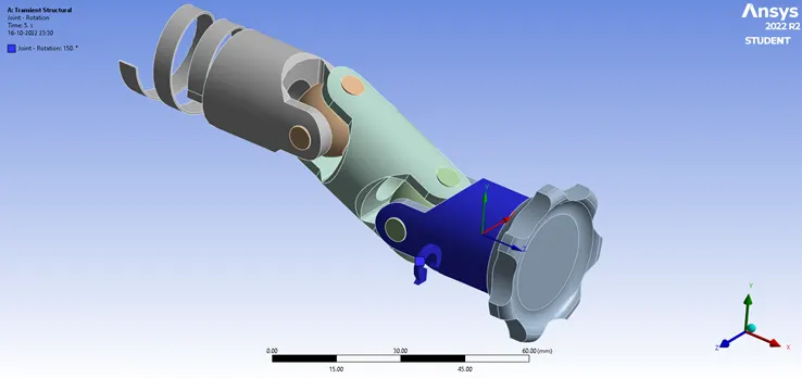
Figure. 17 Joint - Rotation of the Joint with Gear
Case 1
Total Deformation
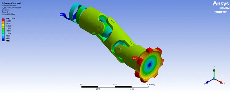
Figure. 19 Total Deformation of the model, Case 1.
Equivalent Stress
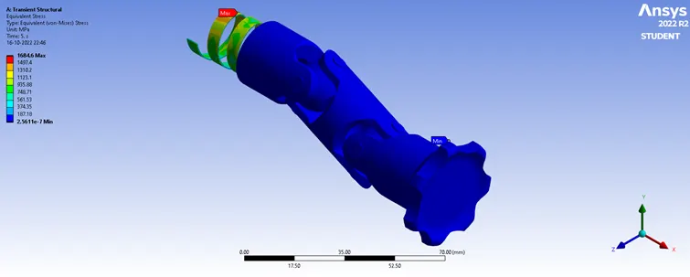
Figure. 20 Equivalent Stress of the model, Case 1.
Total Deformation of Spring
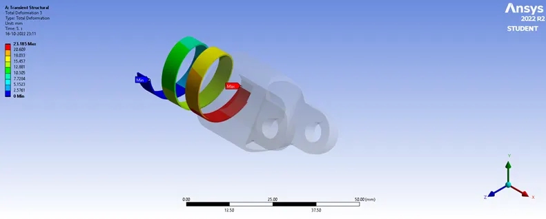
Figure. 21 Total Deformation of the Spring, Case 1.
Case 2
Total Deformation
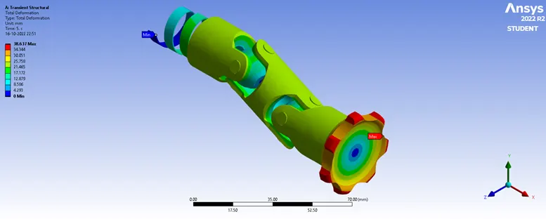
Figure. 22 Total Deformation of the model, Case 2.
Equivalent Stress
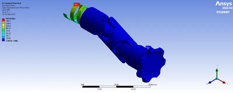
Figure. 23 Equivalent Stress of the model, Case 2.
Total Deformation of Spring
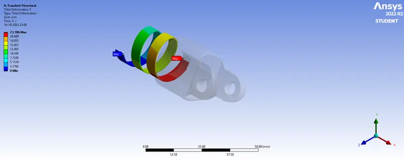
Figure. 24 Total Deformation of the Spring, Case 2.
Case 3
Total Deformation
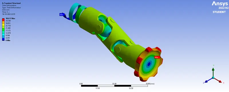
Figure. 25 Total Deformation of the model, Case 3.
Equivalent Stress
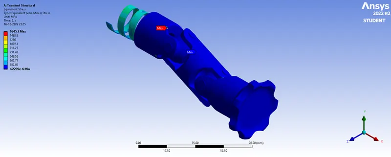
Figure. 26 Equivalent Stress of the model, Case 3.
Total Deformation of Spring
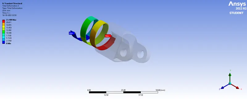
Figure. 27 Total Deformation of the Spring, Case 3.
Comparison of Case 1, Case 2 & Case 3
|
Parameters |
Case 1 |
Case 2 |
Case 3 |
|
Total Deformation |
38.637 mm |
38.637 mm |
38.637 mm |
|
Equivalent Stress |
1684.6 MPa |
1625.8 MPa |
1645.7 MPa |
|
Total Deformation of Spring |
23.185 mm |
23.186 mm |
23.188 mm |
Conclusion
- The total deformation is same for all the three cases this is due to that the maximum total deformation occurred in the gear region in all the three cases.
- The Equivalent Stress is higher in Case 1 (Structural Steel) than other two cases (Stainless Steel Titanium alloy). As the structural steel has the highest value of Youngs modulus of all three materials hence the stress is maximum in Structural Steel
- The total deformation of the Spring also same of three cases only a small minor value Changes has been reflected which is negligible.