Assignment 5-RADIOSS Interfaces & Study of Effect of Notches Challenge
RADIOSS Interfaces & Study of Effect of Notches Challenge
RADIOSS Interfaces & Study of Effect of Notches Challenge
Objective:
To perform simulation as per the Models and their cases given below.
Model 1: To create mesh for bumper assembly with 6mm mesh size.
Model 2: To simulate the given model as per given six different cases in radioss.
CASE 1:Run the crash tube model as it is
CASE 2: Change the Inacti=6 and run.
CASE 3: Create the type 11 contact and run.
CASE 4: Remove both notches and remove boundary condition on rigid body node then run.
CASE 5: Create a new notch in the middle ,select the whole section and run.
CASE 6: Create a new notch with nodes only from opposing 2 faces and run.
Model 1
Procedures:
The given bumper assembly model is imported to hyperworks as displayed in Figure 1.
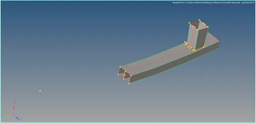
Figure 1: Imported bumper assembly model
The unwanted nodes are removed using temp nodes and the middle surface is connected with the top and bottom surface using extend command in the surface edit option. The refined model is shown in Figure 2.
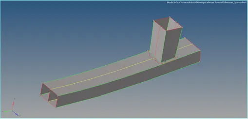
Figure 2: Refined bumper assembly model
Meshing is performend with Auto mesh option from the 2D panel. Give the Element size as 6 then click mesh. The meshed surface is shown in Figure 3.
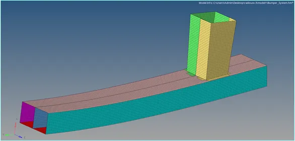
Figure 3: Meshed bumper assembly model
The dis connected surfaces are connected using Connector option from the 1D panel. Give the spot option and weld as type by assigning the nodes with components then click Create. The horizontal Connector is shown in figure 4 and the vertical Connector is shown in figure 5
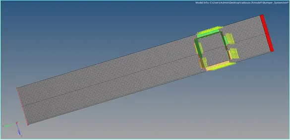
Figure 4: Bumper assembly horizontal Connector
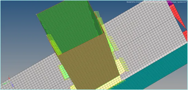
Figure 5: Bumper assembly vertical Connector
Model 1
Case 1: Run the crash tube model as it is.
The given Crash_Tube_0000.rad file is imported to hyperworks and shaded elems view is displayed in Figure 6.
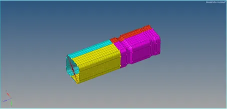
Figure 6
Click on the output Blocks and then construct the TH PART, stay with components in place of nodes in entity id as shown in figure 7. As displayed in the figure 8 Keep the self contact card image as it is.
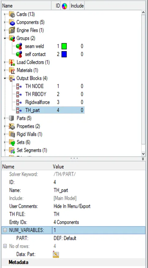
Figure 7:
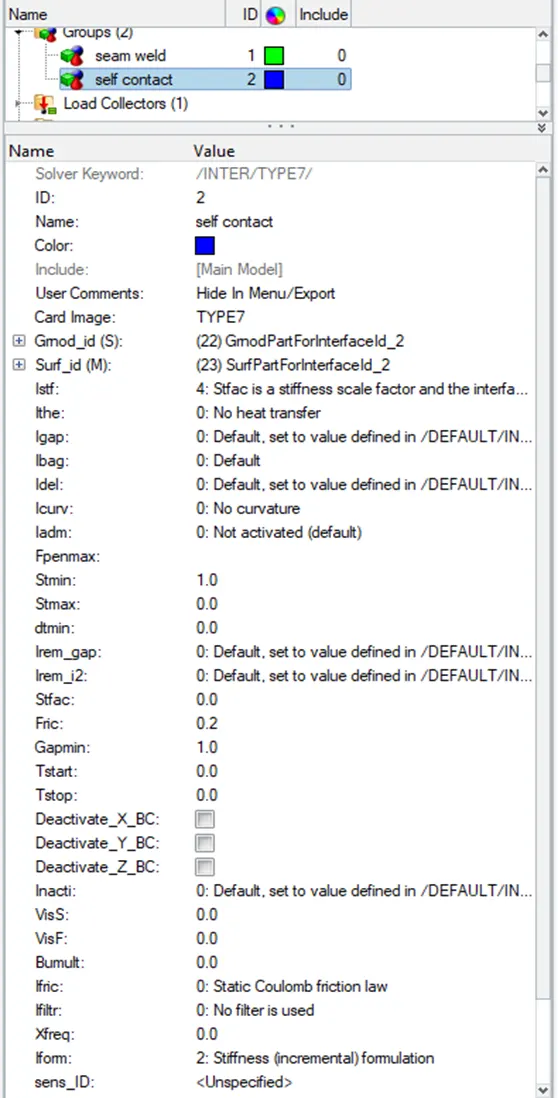
Figure 8:
Go to the Analysis tab and choose the Radioss option to simulate the model. To save the file, choose a location. Check include collectors box and In the options tab keep type “-nt 4” then Click Radioss.

Figure 9:
it will show RADIOSS JOB IS COMPLETED in Console solver view tab as displayed in Figure 10.
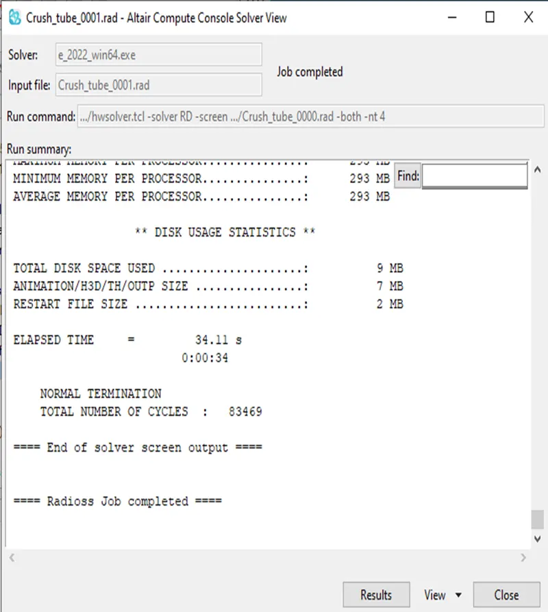
Figure 10:
Click on RESULT in that tab, it will direct to hyperview where the animation of the simulation is viewed. Animation file are in name of h3d will be in the load area in this panel then switch to contour mode in the panel and assign the result type as Von Mises(s) with scalar value and click apply.
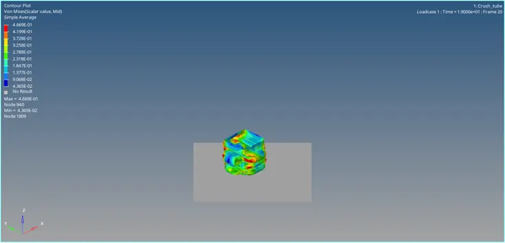
Figure 11:
In same way assign the result type as contact force and click apply.
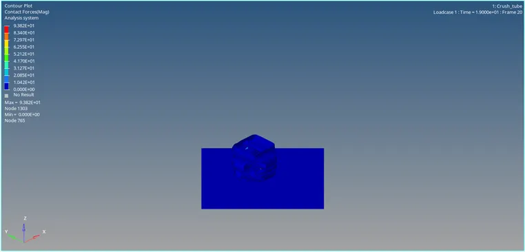
Figure 12:
Open output of simulation in 0001.out file which is generated after the simulation. The final energy error is -3.8 percentage, which lies in between the safe tolerance percentage as shown in Figure 13. i.e,safe tolerance percentage = -15% TO +5%
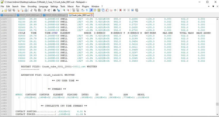
Figure 13:
Case 2: Change the Inacti=6 and run.
In the same way change the Inacti=6 and run as shown in Figure 14.
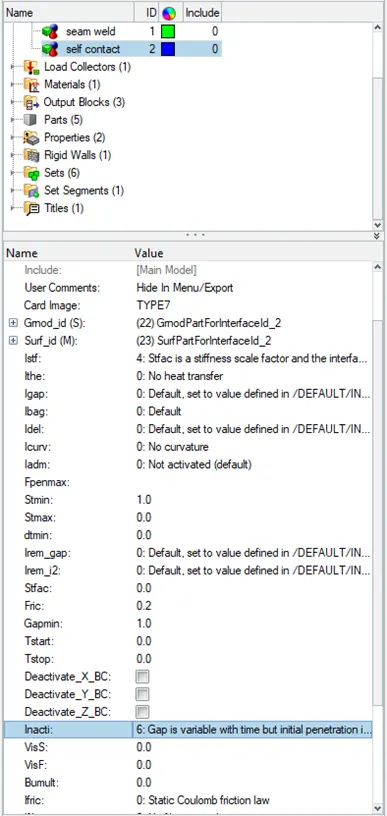
Figure 14:
Console solver view tab as displayed in Figure 15.
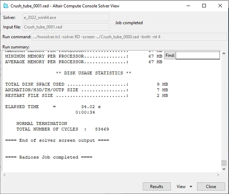
Figure 15:
Click on RESULT in that tab, it will direct to hyperview where the animation of the simulation is viewed. Animation file are in name of h3d will be in the load area in this panel then switch to contour mode in the panel and assign the result type as Von Mises(s) with scalar value and click apply.
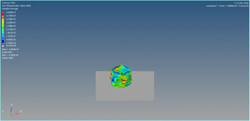
Figure 16:
In same way assign the result type as contact force and click apply.
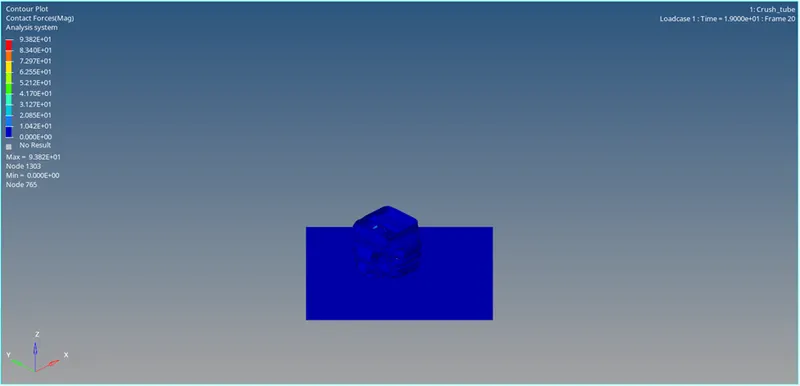
Figure 17:
Open output of simulation in 0001.out file which is generated after the simulation. The final energy error is -3.8 percentage, which lies in between the safe tolerance percentage as shown in Figure 18. i.e,safe tolerance percentage = -15% TO +5%
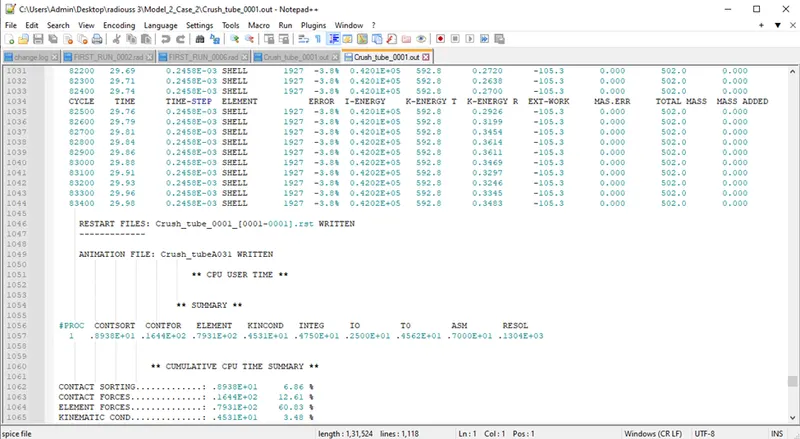
Figure 18:
Case 3: Create the type 11 contact and run.
In the same way change the card image to type 11 in the self contact group and run as shown in Figure 19.
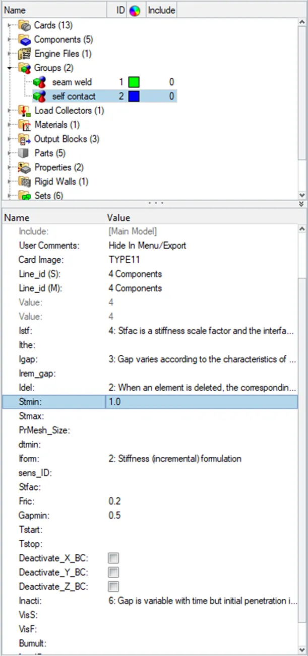
Figure 19:
Console solver view tab as displayed in Figure 20.
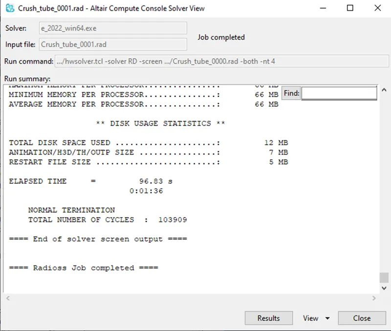
Figure 20:
Click on RESULT in that tab, it will direct to hyperview where the animation of the simulation is viewed. Animation file are in name of h3d will be in the load area in this panel then switch to contour mode in the panel and assign the result type as Von Mises(s) with scalar value and click apply.
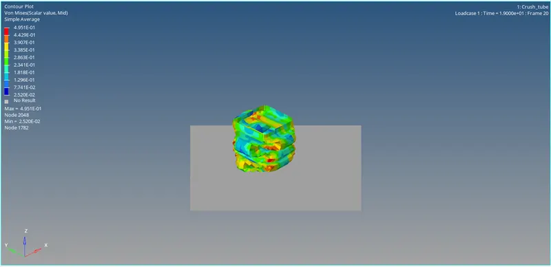
Figure 21:
In same way assign the result type as contact force and click apply.
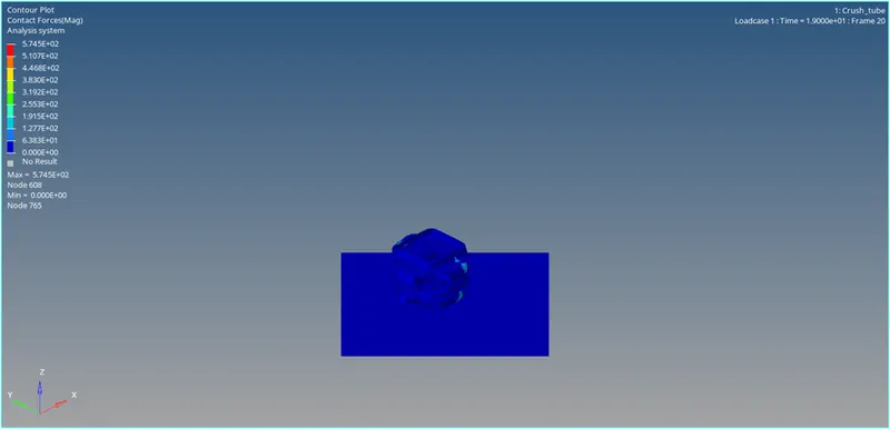
Figure 22:
Open output of simulation in 0001.out file which is generated after the simulation. The final energy error is -7.5 percentage, which lies in between the safe tolerance percentage as shown in Figure 23. i.e,safe tolerance percentage = -15% TO +5%
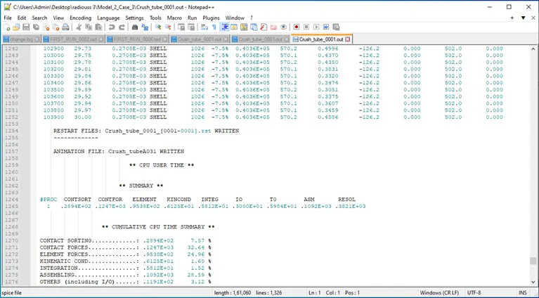
Figure 23:
Case 4: Remove both notches and remove boundary condition on rigid body node then run.
Remove the notches using the align node command in the node edit as shown in Figure 24 and delete the boundary condition from the solver tab which can be taken from the view tool bar as hoen in Figure 25. Then follow the similar steps.
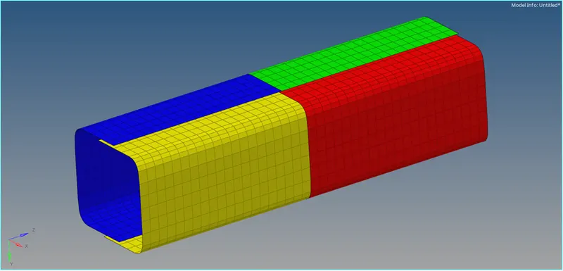
Figure 24:
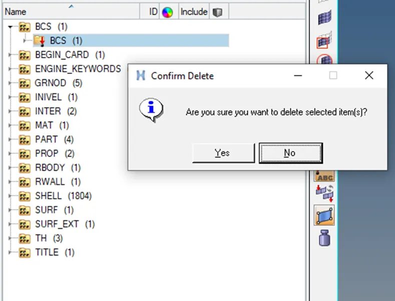
Figure 25:
Console solver view tab as displayed in Figure 26.
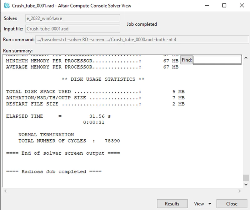
Figure 26:
Click on RESULT in that tab, it will direct to hyperview where the animation of the simulation is viewed. Animation file are in name of h3d will be in the load area in this panel then switch to contour mode in the panel and assign the result type as Von Mises(s) with scalar value and click apply.
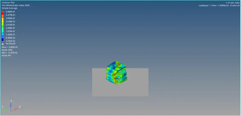
Figure 27:
In same way assign the result type as contact force and click apply.
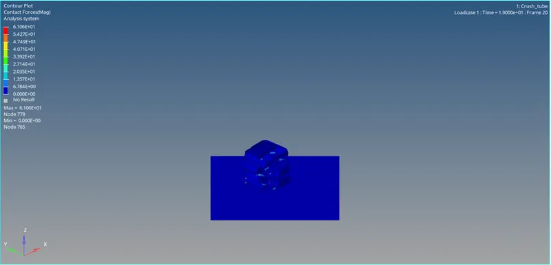
Figure 28:
Open output of simulation in 0001.out file which is generated after the simulation. The final energy error is -8.0 percentage, which lies in between the safe tolerance percentage as shown in Figure 29. i.e,safe tolerance percentage = -15% TO +5%
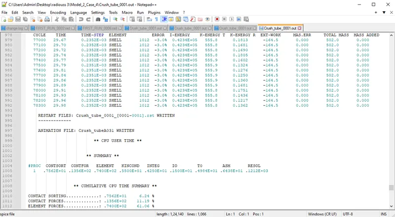
Figure 29:
Case 5: Create a new notch in the middle ,select the whole section and run.
In the same way remove the notches using align node command and then create a new notch using translate command with reference with the given notches as shown in Figure 30.
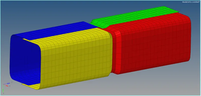
Figure 30:
Keep the same card image as Type 11 as shown in figure 31.
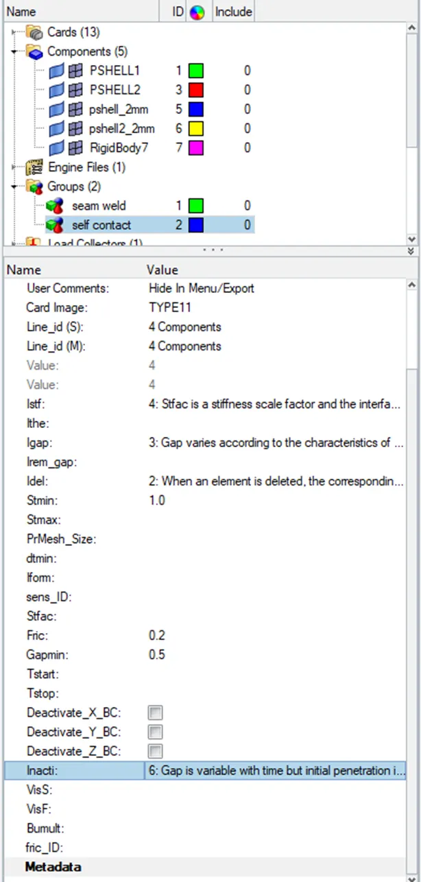
Figure 31:
Console solver view tab as displayed in Figure 32.
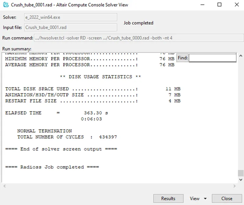
Figure 32:
Click on RESULT in that tab, it will direct to hyperview where the animation of the simulation is viewed. Animation file are in name of h3d will be in the load area in this panel then switch to contour mode in the panel and assign the result type as Von Mises(s) with scalar value and click apply.
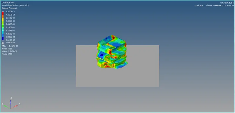
Figure 33:
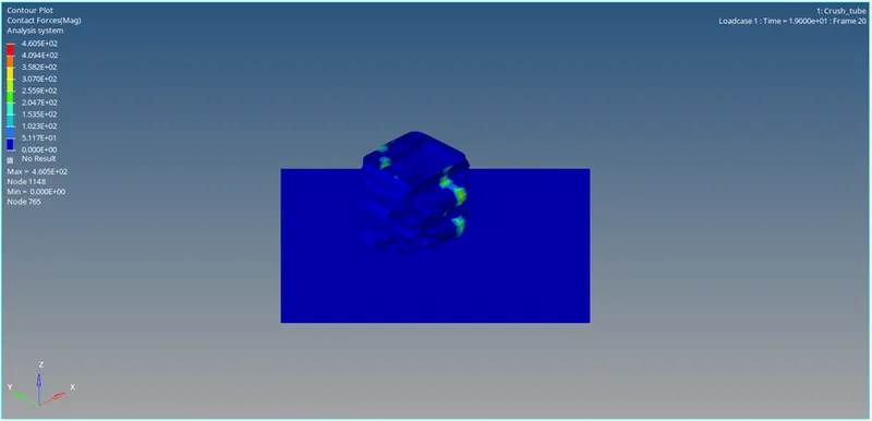
Figure 34:
Open output of simulation in 0001.out file which is generated after the simulation. The final energy error is -3.9 percentage, which lies in between the safe tolerance percentage as shown in Figure 35. i.e,safe tolerance percentage = -15% TO +5%
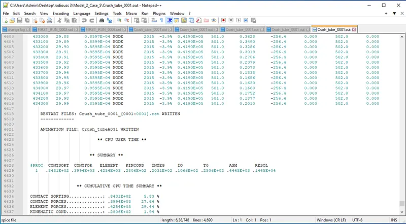 Figure 35:
Case 6: Create a new notch with nodes only from opposing 2 faces and run.
Similar to Case 5 create notches but only on the opposite 2 faces as shown in Figure 36
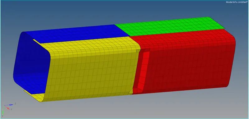
Figure 36:
Keep the same card image as Type 11 as shown in figure 37.
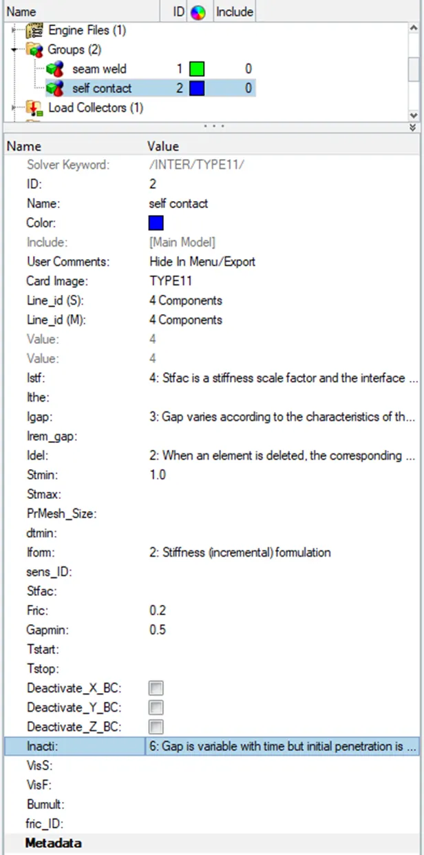
Figure 37:
Console solver view tab as displayed in Figure 38.
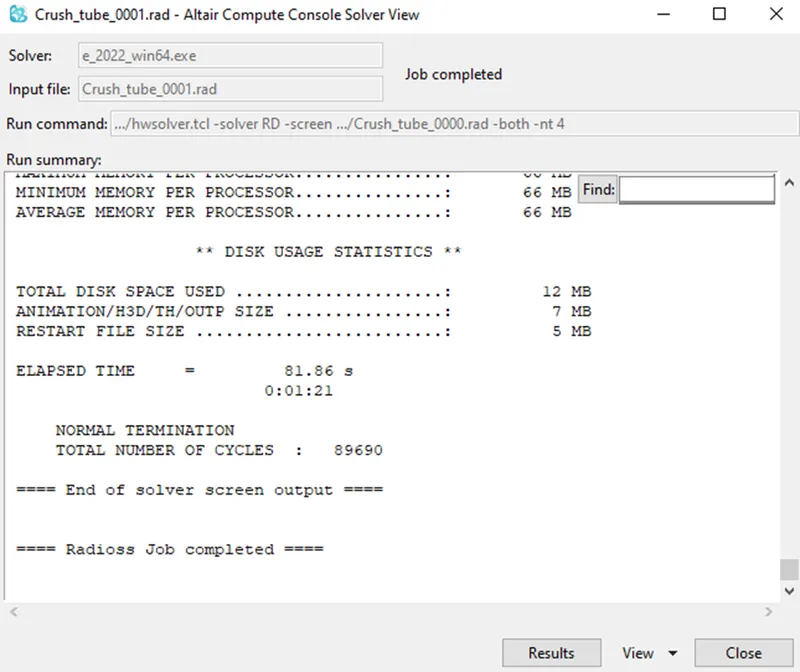
Figure 38:
Click on RESULT in that tab, it will direct to hyperview where the animation of the simulation is viewed. Animation file are in name of h3d will be in the load area in this panel then switch to contour mode in the panel and assign the result type as Von Mises(s) with scalar value and click apply.
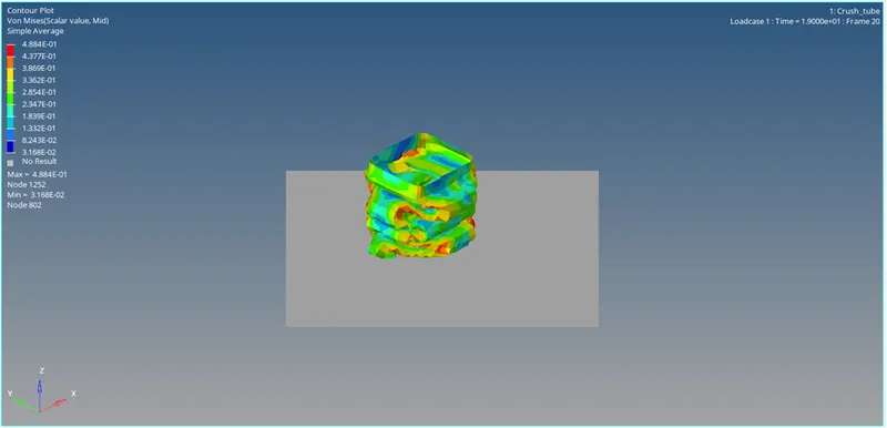
Figure 39:
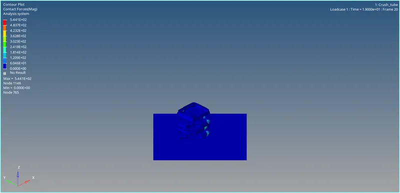
Figure 40:
Open output of simulation in 0001.out file which is generated after the simulation. The final energy error is -7.1 percentage, which lies in between the safe tolerance percentage as shown in Figure 41. i.e,safe tolerance percentage = -15% TO +5%
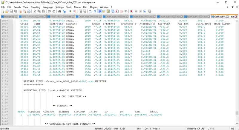
Figure 41:
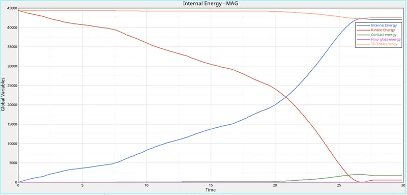
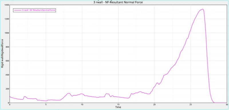
Case1
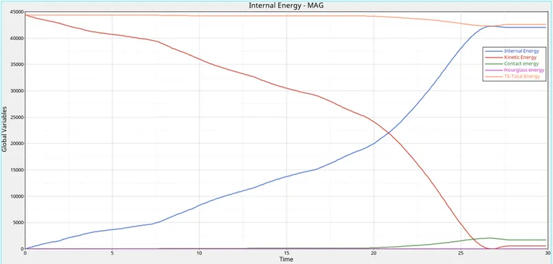
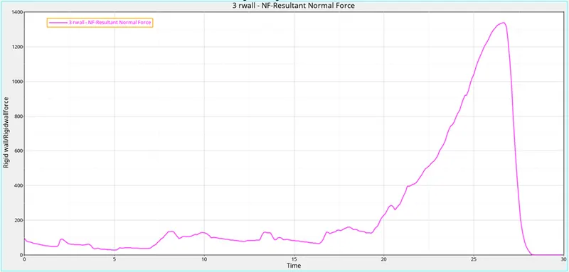
Case2
Case3
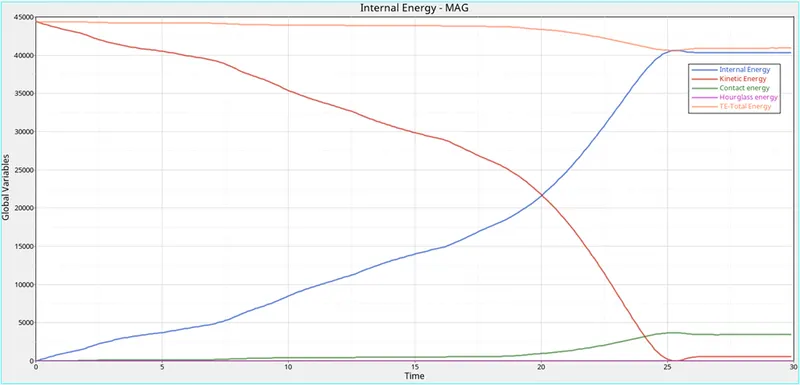
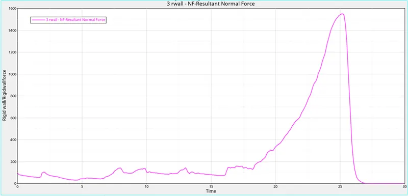
Case4
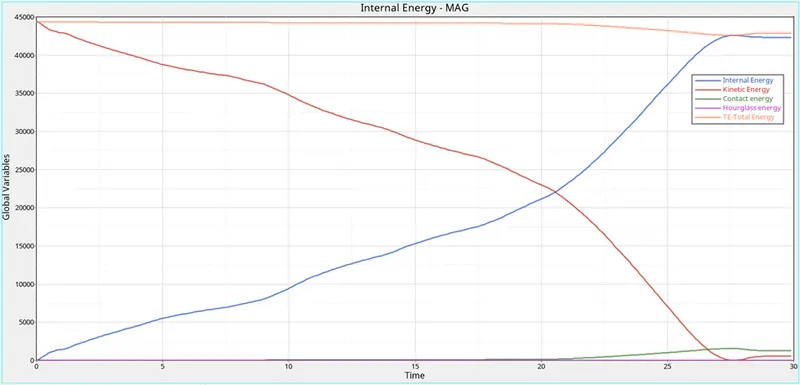
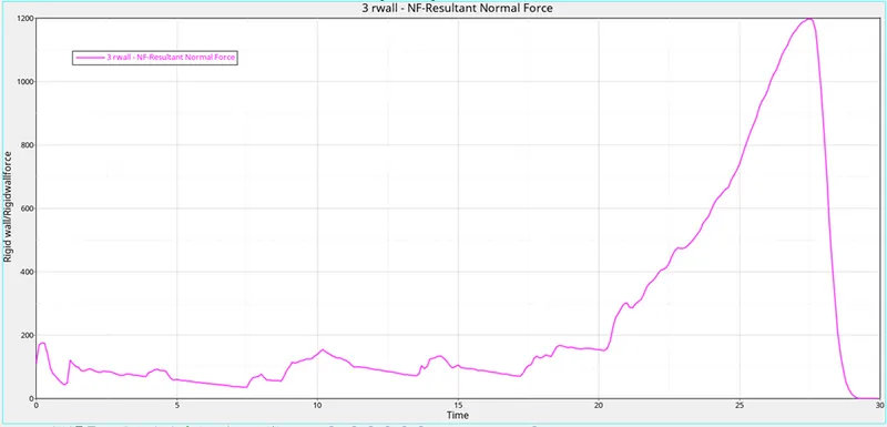
Case5
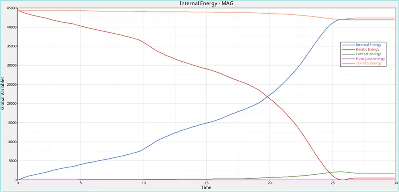
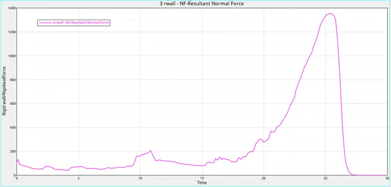
Case6
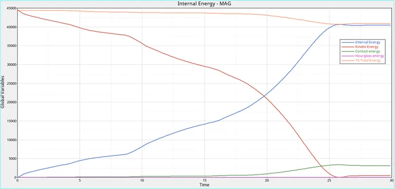
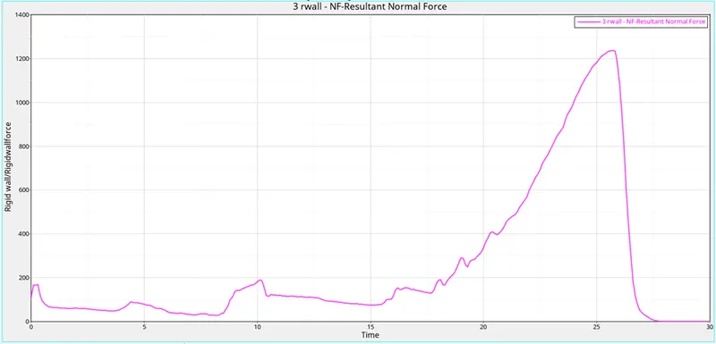
Conclusion
- Energy error for all cases is between -15% TO +5% which is acceptable.
- It has been noted that case 4, in which the notch is removed, results in the least amount of stress being applied to the crush tube. The notch-equipped crush tube experiences stress concentration.
- Deformation begins in certain places first. For components with notches, the deformations are predictable. Like in the case 1 scenario with Inacti = 0 shows no initial penetration.