Week 3 Verification of Weld Joints
STRUCTURAL ANALYSIS FOR VERIFICATION OF WELD JOINTS
Objective
To examine and analyse the weld joints utilising three weld materials cases, then contrast the outcomes
Case 1
To use Stainless Steel as the overall Model Material
Case 2
To use Aluminium Alloy (high strength, wrought) as the Weldment Material and Stainless Steel as plates and ribs material.
Case 3
To use Cast Bronze as the Weldment Material, Stainless Steel as plates material and Cast Copper as ribs material.
To conduct the simulation for a 15000 N load that will be applied to the little plate's rectangular hole in all three cases.
To determine the Directional Deformation and Equivalent Elastic Strain that each case's experienced.
To identify which weld joint in each case experiences the most equivalent stress and to compare the outcomes for all three cases.
Material data
Figure. 1 shows the structural steel's properties in Ansys Workbench engineering data. It was used as the weld joints model's material input.
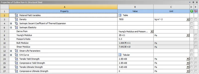
Figure. 1 Structural steel Engineering data
Figure. 2 shows the Aluminium Alloy (high strength, wrought) properties in Ansys Workbench engineering data. It was used as the Weld Material in the weld joints model's material input.
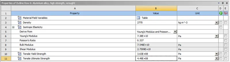
Figure. 2 Aluminium Alloy (high strength, wrought) Engineering data
Figure. 3 shows the Cast Bronze properties in Ansys Workbench engineering data. It was used as the Weld Material in the weld joints model's material input.
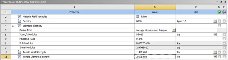
Figure. 3 Cast Bronze Engineering data
Figure. 4 shows the Cast Copper properties in Ansys Workbench engineering data. It was used as the ribs material in the weld joints model's material input.
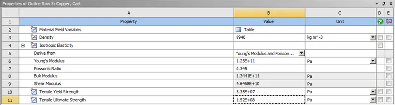
Figure. 4 Cast Copper Engineering data
Model Geomentry
Figure. 5 shows the imported given weld joint model in the mechanical modular.
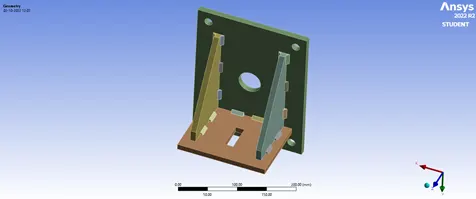
Figure. 5 Weld Joint Model
Contact and Target faces
Initially, the models are renamed Big plate, Small plate, Rig 1 and Rig 2. Figure. 6 shows the connections between the Big plate and Small plate. In that the Big plate is assigned as “Contact bodies” and the Small plate is assigned as “Target bodies”. The conncetion is assigned as Frictional contact.
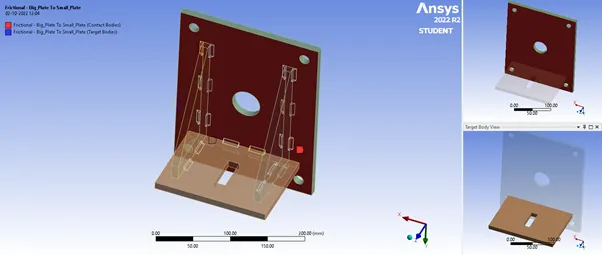
Figure. 6 Frictional - Big plate To Small plate connection.
Figure. 7 shows the connections between the Big plate and Rig 1. In that the Big plate is assigned as “Contact bodies” and the Rig 1 is assigned as “Target bodies” The conncetion is assigned as Frictional contact.
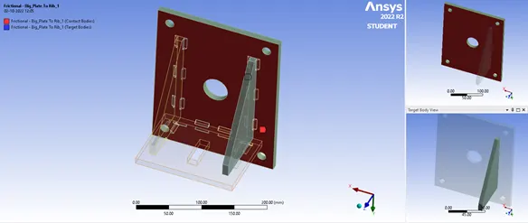
Figure. 7 Frictional - Big plate To Rig 1 connection.
Figure. 8 shows the connections between the Big plate and Rig 2. In that the Big plate is assigned as “Contact bodies” and the Rig 2 is assigned as “Target bodies” The conncetion is assigned as Frictional contact.
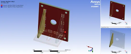
Figure. 8 Frictional - Big plate To Rig 2 connection.
Figure. 9 shows the connections between the Small plate and Rig 1. In that the Small plate is assigned as “Contact bodies” and the Rig 1 is assigned as “Target bodies” The conncetion is assigned as Frictional contact.
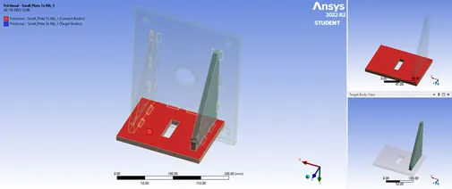
Figure. 9 Frictional - Small plate To Rig 1 connection.
Figure. 10 shows the connections between the Small plate and Rig 2. In that the Small plate is assigned as “Contact bodies” and the Rig 2 is assigned as “Target bodies” The conncetion is assigned as Frictional contact.
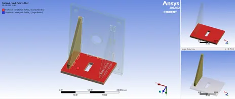
Figure. 10 Frictional - Small plate To Rig 2 connection.
Meshing
The meshing of the model was default meshed then the body size of 7mm mesh was assigned for the big plate and small plate as shown in Figure. 11. The over all mesh was shown in Figure. 12.
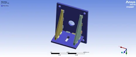
Figure. 11 Body sizing assigning of big and small plates
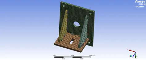
Figure. 12 Overall meshed model
Joints and loads
Since the model is designed for wall fixed product the five hole faces of the Big plate will be fixed supported. The fixed joints are shown in Figure. 13.
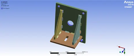
Figure. 13 Fixed Joint
The load acts on the Small plate’s hole hence the four faces are assigned a load of 15000 N is assigned as shown in Figure. 14.
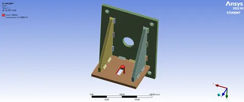
Figure. 14 Load Joint
Simulation results
Case 1
Directional Deformation
Figure. 14 shows the Directional Deformation of the weld joint model assigned with Structural steel material for all bodies of the model. The directional deformation is along Y axis.
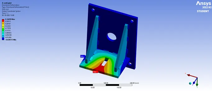
Figure. 14 Directional Deformation of the weld joint model (Structural steel)
Equivalent Elastic Strain
Figure. 15 shows the Equivalent Elastic Strain of the weld joint model assigned with Structural steel material for all bodies of the model. Figure. 16 shows the Equivalent Elastic Strain of the rigs on weld joint model assigned with Structural steel material. Figure. 17 shows the Equivalent Elastic Strain of the weldment on weld joint model assigned with Structural steel material.
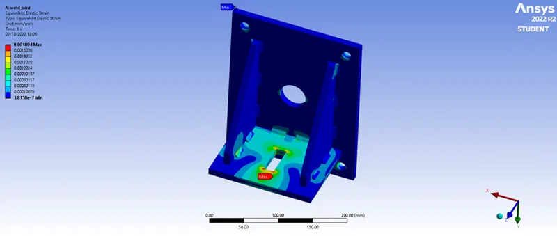
Figure. 15 Equivalent Elastic Strain of the weld joint model (Structural steel)
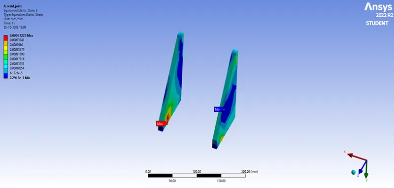
Figure. 16 Equivalent Elastic Strain of Rigs (Structural steel)
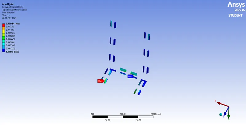
Figure. 17 Equivalent Elastic Strain of weldment (Structural steel)
Case 2
Directional Deformation
Figure. 18 shows the Directional Deformation of the weld joint model assigned with Aluminium Alloy (high strength, wrought) as Weldment Material and Structural steel material for all other bodies of the model. The directional deformation is along Y axis.
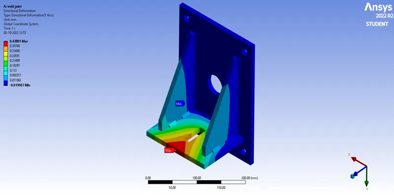
Figure. 18 Directional Deformation of weld joint model (Aluminium Alloy & Structural steel)
Equivalent Elastic Strain
Figure. 19 shows the Equivalent Elastic Strain of the weld joint model assigned with Aluminium Alloy (high strength, wrought) as Weldment Material and Structural steel material for all other bodies of the model. Figure. 20 shows the Equivalent Elastic Strain of the rigs on weld joint model assigned with Structural steel material. Figure. 21 shows the Equivalent Elastic Strain of the weldment on weld joint model assigned with Aluminium Alloy (high strength, wrought) material.
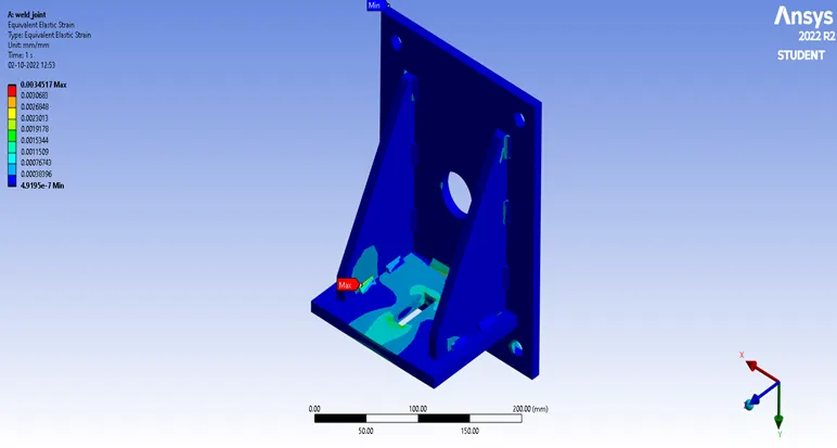
Figure. 19 Equivalent Elastic Strain of weld joint model (Aluminium Alloy & Structural steel)
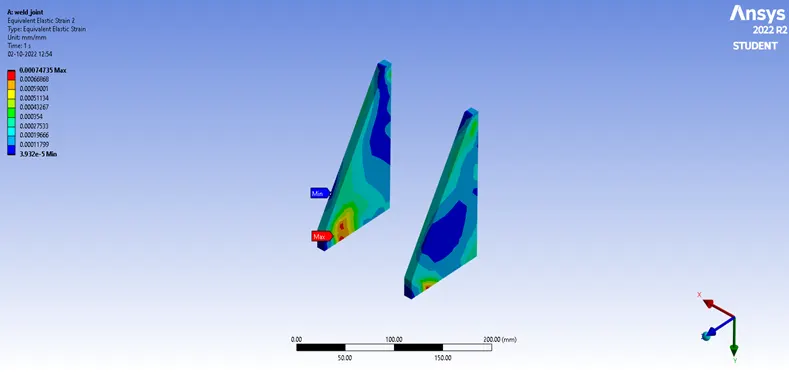
Figure. 20 Equivalent Elastic Strain of Rigs (Aluminium Alloy & Structural steel)
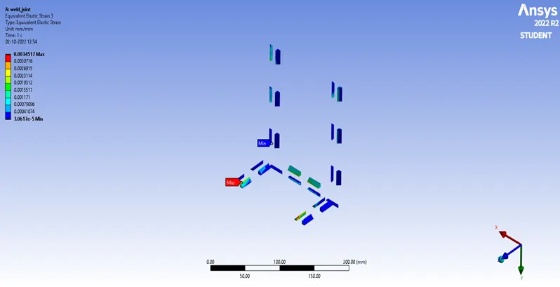
Figure. 21 Equivalent Elastic Strain of weldment (Aluminium Alloy & Structural steel)
Case 3
Directional Deformation
Figure. 22 shows the Directional Deformation of the weld joint model assigned with Cast Bronze as the Weldment Material , Stainless Steel as plates material and Cast Copper as ribs of the model. The directional deformation is along Y axis.
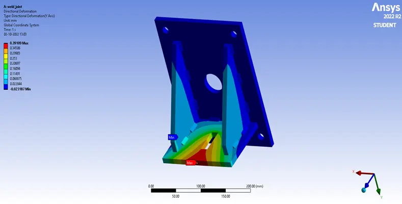
Figure. 22 Directional Deformation of weld joint model (Bronze, Copper & Structural steel)
Equivalent Elastic Strain
Figure. 23 shows the Equivalent Elastic Strain of the weld joint model assigned with Cast Bronze as the Weldment Material , Stainless Steel as plates material and Cast Copper as ribs material of the model. Figure. 24 shows the Equivalent Elastic Strain of the rigs on weld joint model assigned with Cast Copper material. Figure. 25 shows the Equivalent Elastic Strain of the weldment on weld joint model assigned with Cast Bronze material.
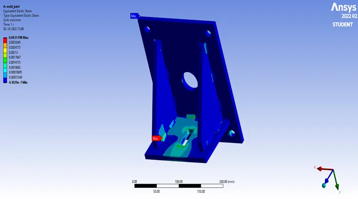
Figure. 23 Equivalent Elastic Strain of weld joint model (Bronze, Copper & Structural steel)
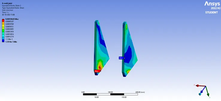
Figure. 24 Equivalent Elastic Strain of Rigs (Bronze, Copper & Structural steel)
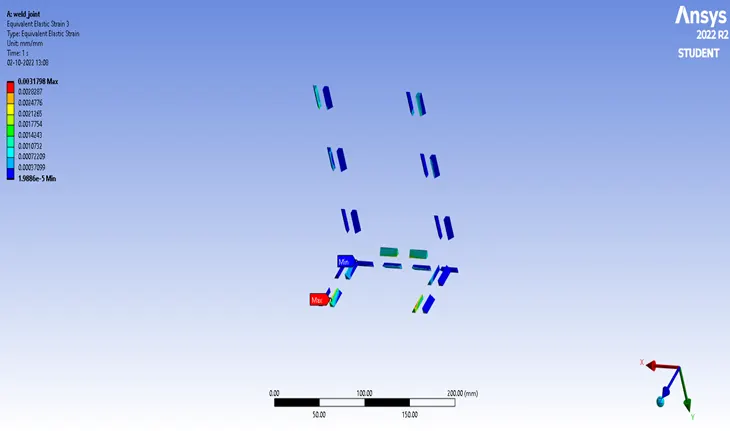
Figure. 25 Equivalent Elastic Strain of weldment (Bronze, Copper & Structural steel)
Comparison of all three cases
|
Materials |
Directional Deformation (mm) |
Equivalent Elastic Strain (mm) |
||
|
Maximum |
Minimum |
Maximum |
Minimum |
|
|
Structural steel |
0.34459 |
- 0.02851 |
0.001804 |
3.8158e-7 |
|
Aluminium Alloy & Structural steel |
0.43881 |
- 0.01990 |
0.003451 |
4.9195e-7 |
|
Cast Bronze, Cast Copper & Structural steel |
0.39109 |
- 0.023187 |
0.003179 |
4.3029e-7 |
Conclusion
- The comparison of the three cases reveals that Case 2 has the maximum deformation and Case 1 has the least deformation. When comparing the equivalent elastic strain in the three cases, Case 2 has the highest value and Case 1 has the lowest value.
- With this comparison on concern to the maximum deformation the Aluminium Alloy (high strength, wrought) as the Weldment Material and Stainless Steel as plates and ribs material is considered as the last option from analysis point of view.
- On concern to the maximum deformation and maximum Equivalent Elastic Strain of Stainless Steel as the over all Model Material is considered as the first option from analysis point of view.
- On concern to comparison of these three cases, Cast Bronze as the Weldment Material , Stainless Steel as plates material and Cast Copper as ribs material is considered as the optimal option from both analysis point of view and manufacturing point of view.