Week 5 Sphere pressing on a plate
STRUCTURAL ANALYSIS FOR SPHERE PRESSING ON A PLATE
OBJECTIVE
- To perform a Static-Structural analysis to simulate a sphere pressing on a plate using ANSYS workbench.
- To use Structural steel for both sphere and plate but the material of the plate must be Structural steel Non Linear.
- To press the sphere onto plate 4mm downwards and retract it.
- To find out the plastic deformation occurring the material.
Material data
Figure. 1 shows the structural steel's properties in Ansys Workbench engineering data. It was used as the sphere body of the sphere pressing model's material input.
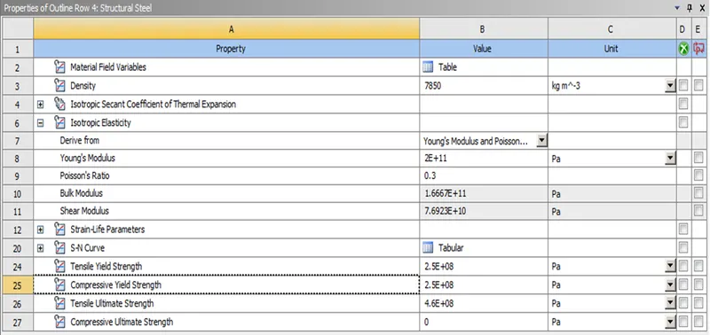
Figure. 1 Structural Steel Engineering Data
Figure. 2 shows the structural steel Non Linear's properties in Ansys Workbench engineering data. It was used as the wire bending model's material input expect the wire.
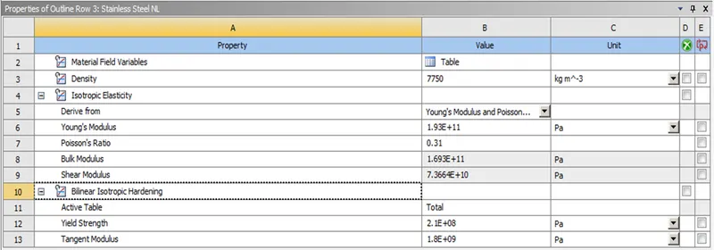
Figure. 2 Structural Steel Non Linear Engineering Data
Model Geomentry
Figure. 3 shows the imported given Sphere Pressing model in the mechanical modular.
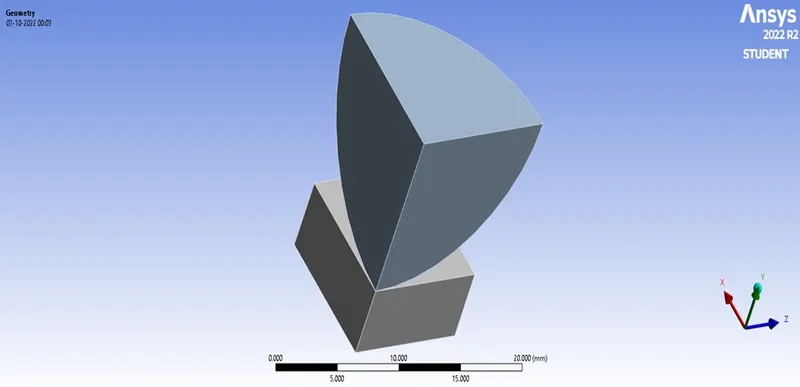
Figure. 3 Sphere Pressing model
Connections
Initially the models are renamed as Sphere and Plate. Figure. 4 illustrates the contact and target faces of the Sphere Pressing model. In which the Sphere is assigned as “Contact Bodies” and the Plate is assigned as “Target Bodies” and The conncetion is assigned as Frictional contact.
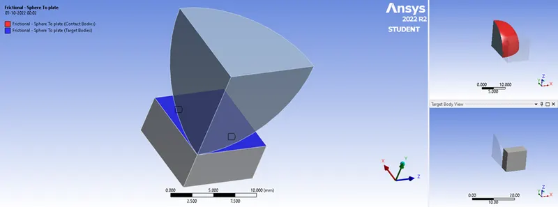
Figure. 4 Frictional-Sphere to Plate.
Meshing
Mesh element size of 0.75 mm was applied and then meshed as shown in Figure. 5.
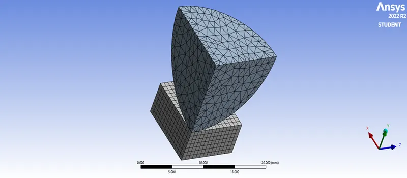
Figure. 5. Meshed Sphere Pressing model
Fixed joint & Displacement joint
The plate is stationary in this simulation hence the bottom face of the plate is fixed by a fixed joint as shown in Figure. 6 and the sphere is on pressing the plate in Y axis in downward direction hence the top face of the sphere is given about a displacement of 4mm in negative Y axis as shown in Figure. 7. In analysis settings the number of steps is assigned as 4, hence the first two steps is for loading and next two steps is for retracting.
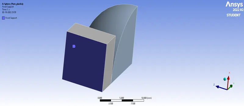
Figure. 6 Fixed Joint of Sphere Pressing model
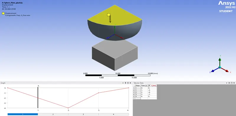
Figure. 7 Displacement Joint of Sphere Pressing model
Simulation results
Directional Deformation
Figure. 8 shows the Directional deformation of the plate with sphere in negative Y axis direction and Figure. 9 shows the Directional deformation of the plate in negative Y axis direction
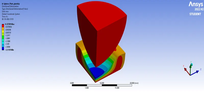
Figure. 8 Directional deformation of the plate with sphere
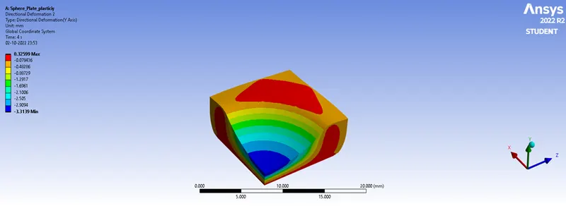
Figure. 9 Directional deformation of the plate
Equivalent Elastic Strain
Figure. 10 shows the Equivalent Elastic Strain of the plate with sphere and Figure. 11 shows the Equivalent Elastic Strain of the plate
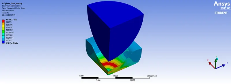
Figure. 10 Equivalent Elastic Strain of the plate with sphere
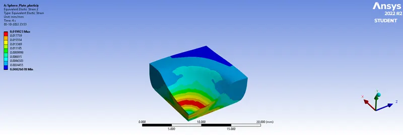
Figure. 11 Equivalent Elastic Strain of the plate
Figure. 12 shows the Equivalent Elastic Strain of the Sphere for all 4 number of steps (4 Seconds).
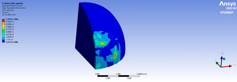
Figure. 12 Equivalent Elastic Strain of the Sphere
Equivalent Stress
Figure. 13 shows the Equivalent Stress of the plate with sphere and Figure. 14 shows the Equivalent Elastic Stress of the plate
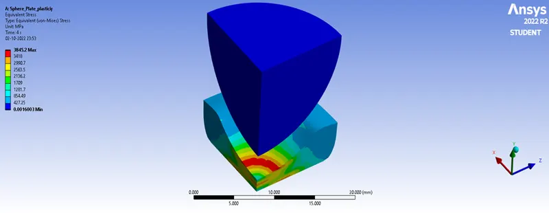
Figure. 13 Equivalent Stress of the plate with sphere
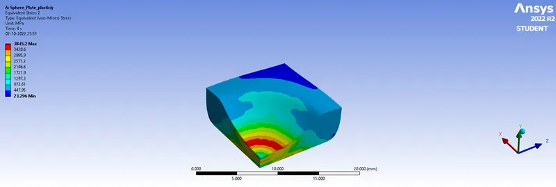
Figure. 14 Equivalent Stress of the plate
Simulation Outcome
|
Plate Materials |
Parameters |
Maximum |
Minimum |
|
Structural steel NL |
Total Deformation |
0.3259 mm |
-3.3139 mm |
|
Equivalent Stress |
3845.2 MPa |
23.296 MPa |
|
|
Equivalent Elastic Strain |
0.01992 mm |
0.00026 mm |
Conclusion
From the above structural analysis of the sphere pressing on a plate, it is clear that sphere and plate exhibit equivalent elastic strain of 0.01992 mm and 0.00026 mm respectively.