Week 3- Geometry cleanup and Mid-surfacing
Geometry cleanup and Mid-surfacing
AIM :
To extract the midsurface, serve connections, and conduct a modal analysis on the blocks with connections.
OBJECTIVE :
Obtaining the tube model's mid-surface extraction and offering a sharing choice for the connection at the tube joint places.
Conducting a modal analysis of the top and bottom blocks in order to examine the findings and confirm connections.
Case1: Midsurface
Step 1: Import the model
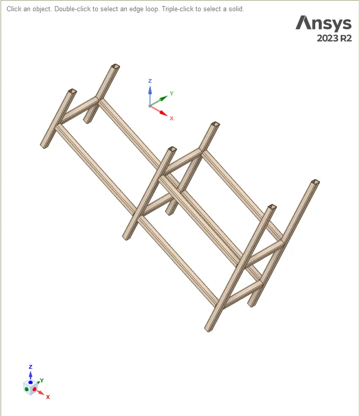
Figure. 1 Imported model
Step 2: Since the tube's thickness is 2.8 mm, we must measure the midsurface of the tube at a distance of 1.4 mm from its outer surface.
Command: Title bar – Prepare – Midsurface – check box the “use selected faces option” – select the faces of the tube – done – Midsurfaces extracted
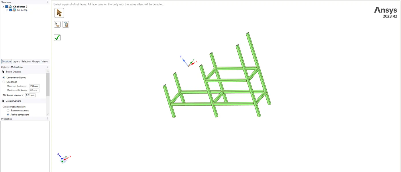
Figure. 2 Selected faces
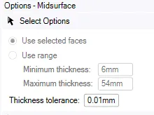
Figure. 3 Midsurface settings
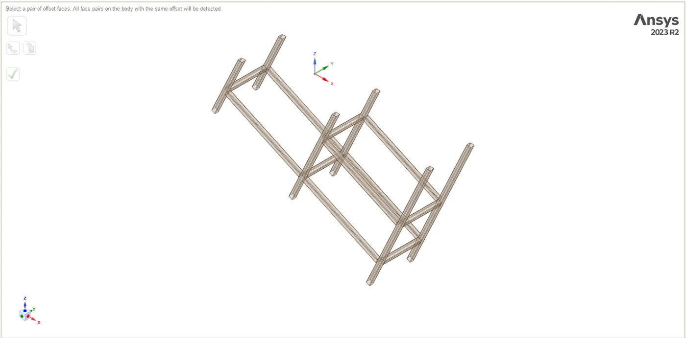
Figure. 4 Midsurface
Step 3:The command below can be used to extend the tubes over one another.
Command: Title bar – Prepare – Extend – selected the edges – added the option of trimmed surfaces – done.
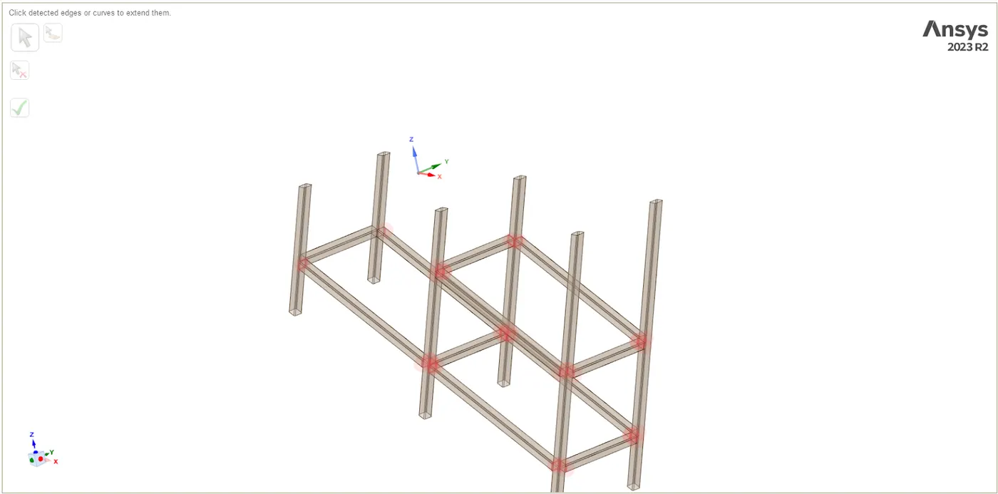
Figure. 5 Free edges
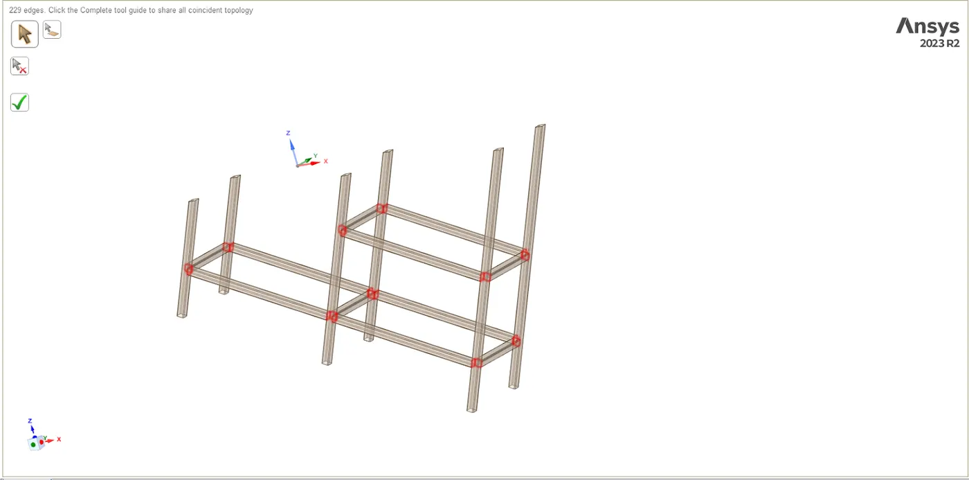
Figure. 6 Extended edges
Step 4:The following command can be used to share the tubes amongst one another.
Command: Title bar – Workbench – Share – shared edges found – done.
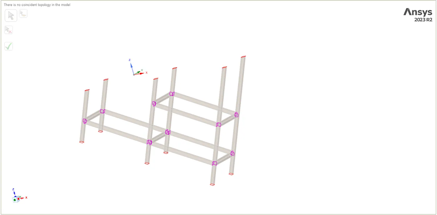
Figure. 7 Connected edges
Case2: Modal analysis
Step 1: Using the command below, a modal analysis project window is created.
Command: Tool box – Analysis system – Click and drag Modal to Project Schematic
Step 2: Material selection
Command: Engineering data – Selected the structural steel material.
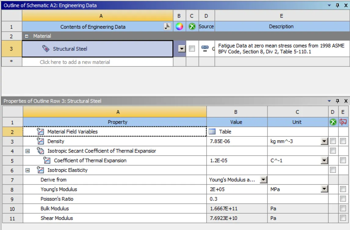
Figure. 1 Selected material
Step 3:To generate the geometry, follow the subsequent commands.
Command: Geometry – New space claim geometry – Title bar – Pick Sketch – Rectangle – Draw 40mmX40mm — Pick Pull – Extrude the sketch 10mm in Y axis.
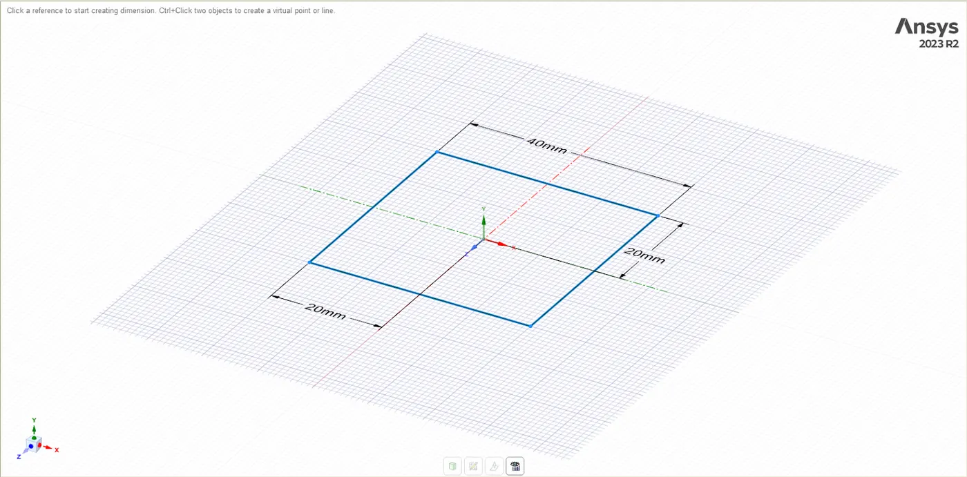
Figure. 2 Sketch of bottom box
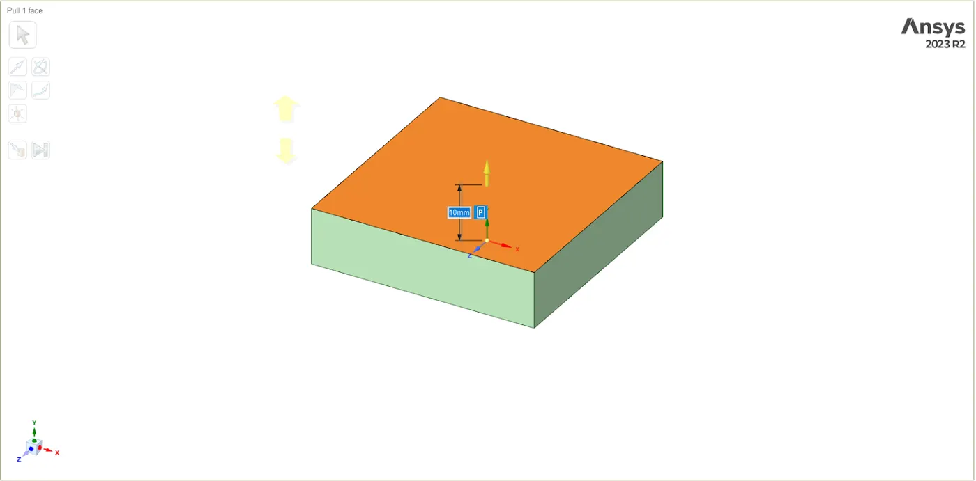
Figure. 3 Extrude of bottom box
Command: Title bar – Pick Sketch – Rectangle – Select the top face of the Extruded cube – Draw 20mmX20mm – Pick Pull – Extrude the sketch 5mm in Y axis.
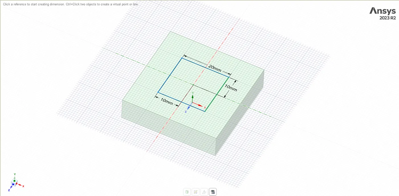
Figure. 4 Sketch of top box
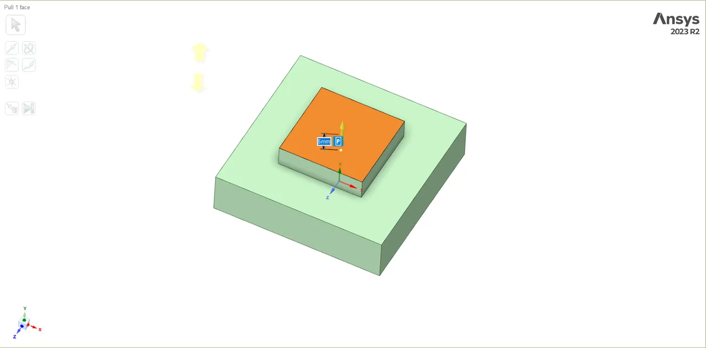
Figure. 5 Extrude of top box
Command: Tile bar – Design – Split body – Select body – Select the plane which will split it into two bodies.
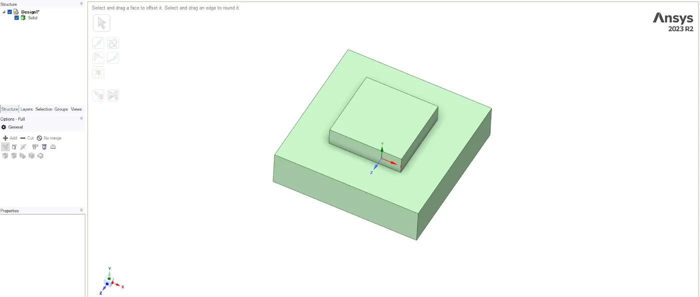
Figure. 6 Single model
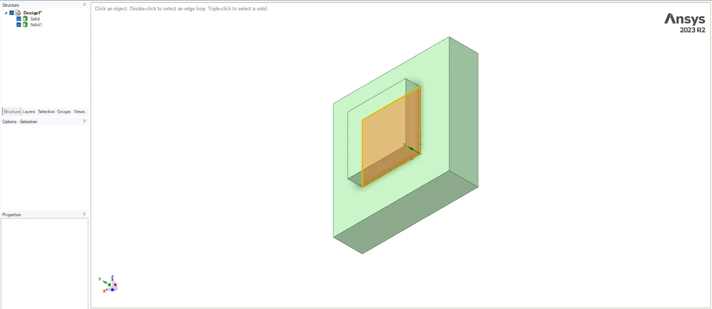
Figure. 7 Split model
Command: Title bar – Workbench – Share – Select body – Done.
Shared Model is created
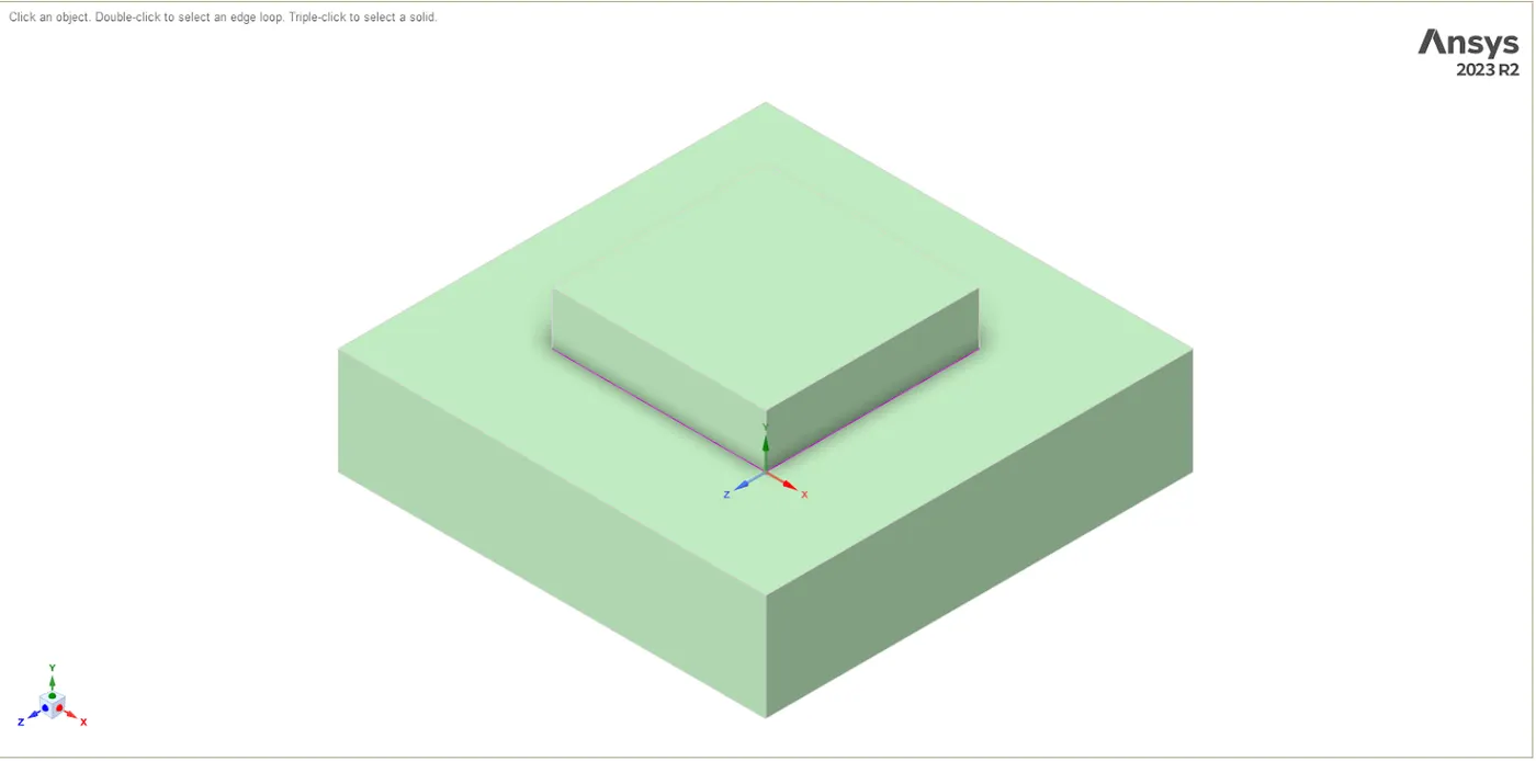
Figure. 8 Connected model
Step 4: To generate the Mesh, follow the subsequent commands.
In ansys mechanical
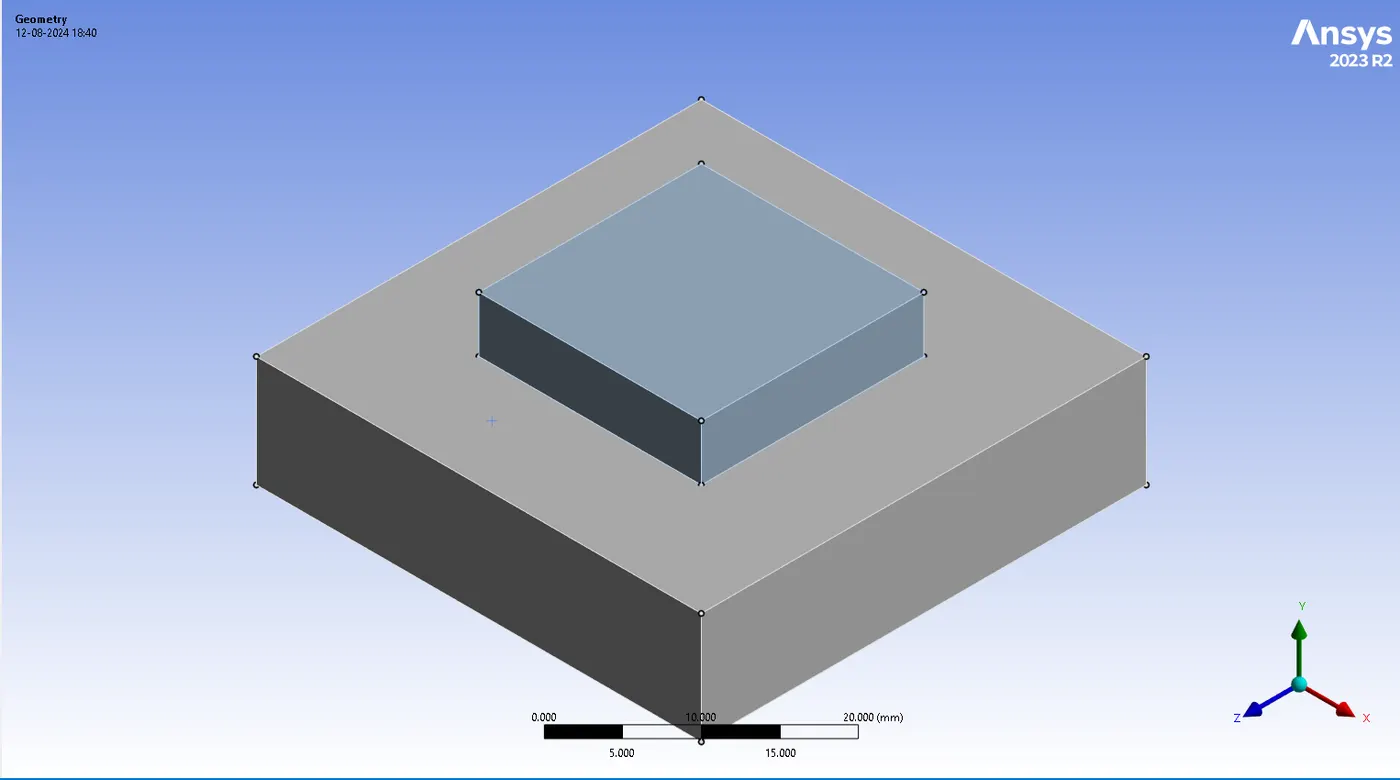
Figure. 9 Model in Mechanical modular
Command: Mesh – Method – Select geometry – Hex dominant method – done.
Command: Mesh – Sizing – Select geometry – element size – 2.5 mm – done.
Command: Mesh – Generate mesh.
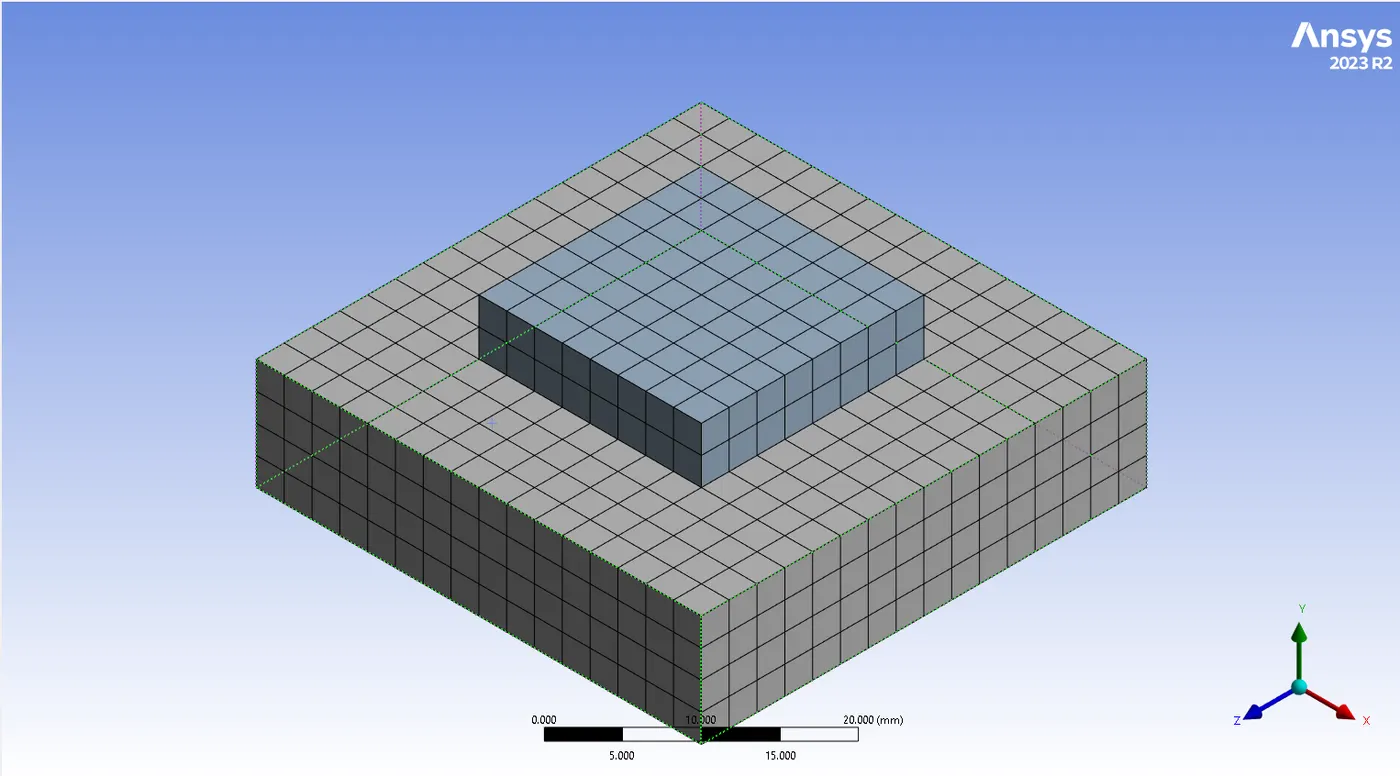
Figure. 10 Meshed model
Step 5: To generate the Boundary condition, follow the subsequent command.
Command: Modal – Fixed support – select bottom face of Block B – Apply.
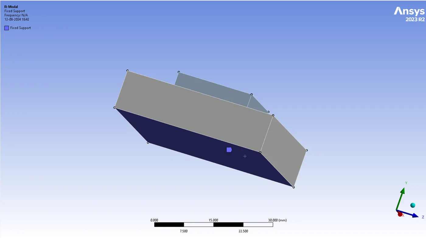
Figure. 11 Fixed model
Step 6: To generate the Analysis Settings, follow the subsequent command.
Command: Modal – Analysis settings – Max modes to find is 12 – Done.
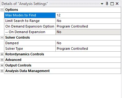
Figure. 12 Total number of modes
Step 7: To Solve, follow the subsequent command.
Command: Modal – Solution – Solve – Done.
Step 8: To generate the preprocessing, follow the subsequent command.
Command: Selected all data in column wise in frequency table – Right click – Create mode shape results from of total deformation – Solution – Right click – Evaluate all results
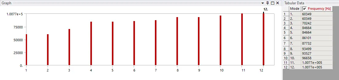
Figure. 13 Frequence for the respective modes
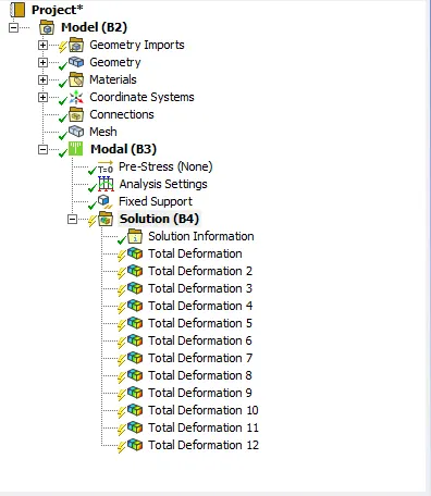
Figure. 14 Total deformation for respective Frequence
Mode shape results

Figure. 15 Mode 1
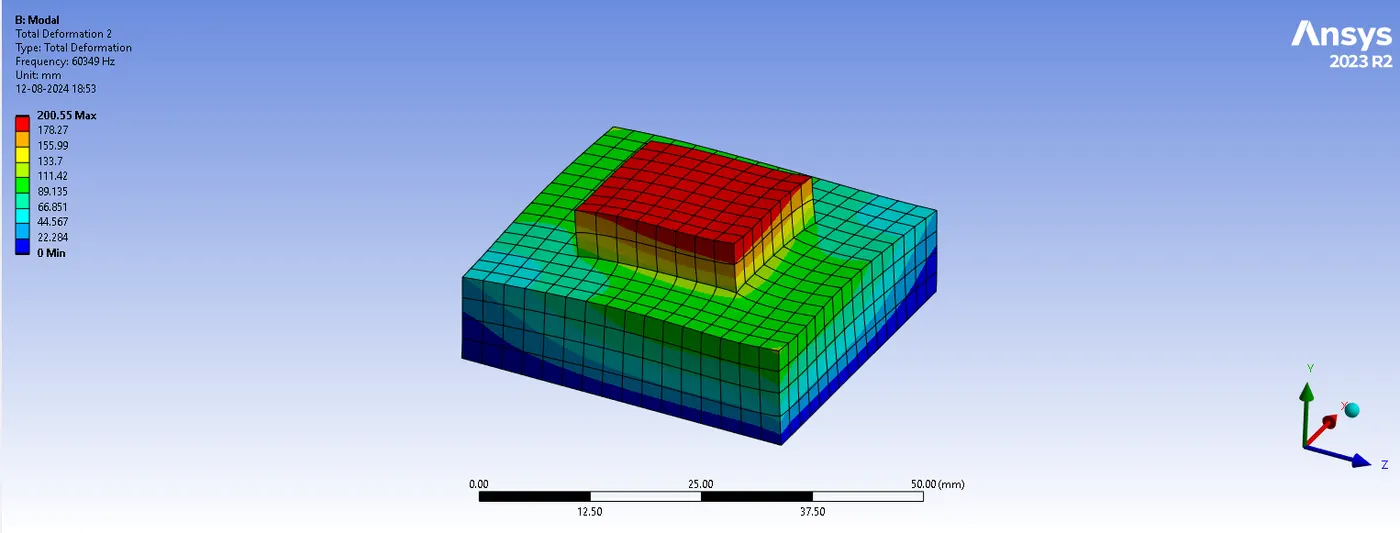
Figure. 15 Mode 2
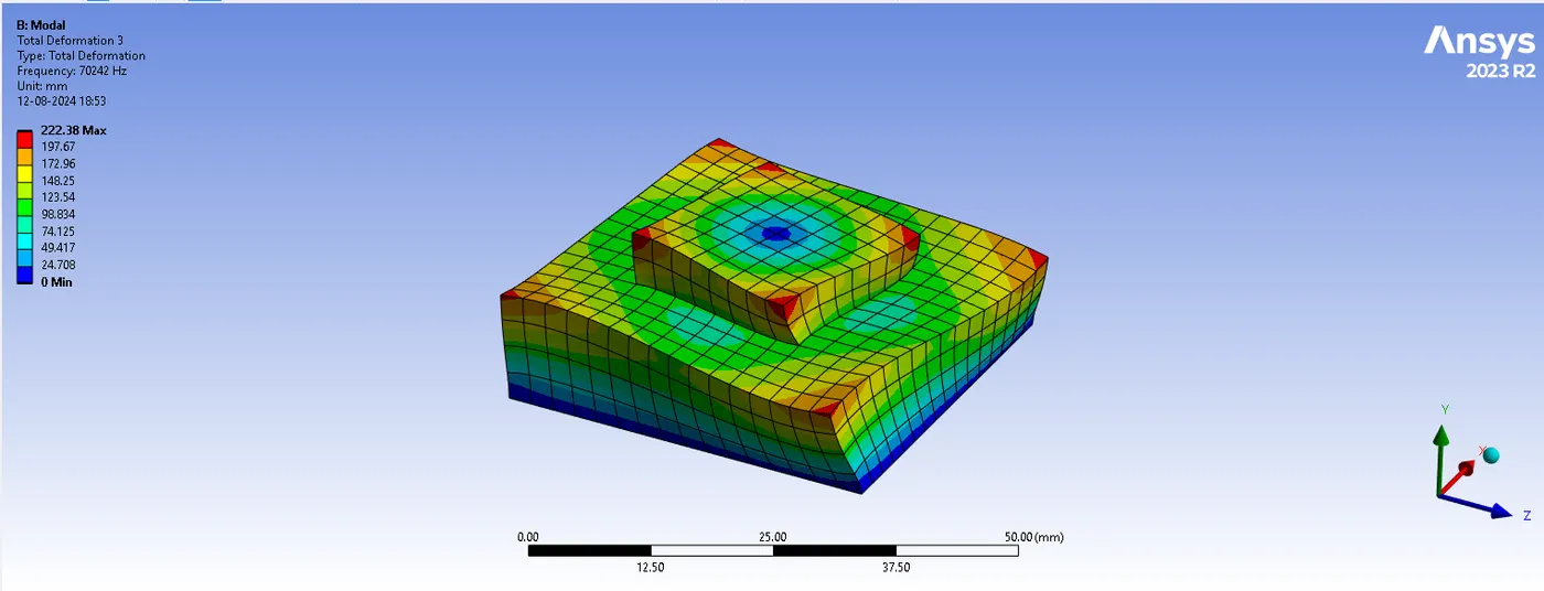
Figure. 16 Mode 3
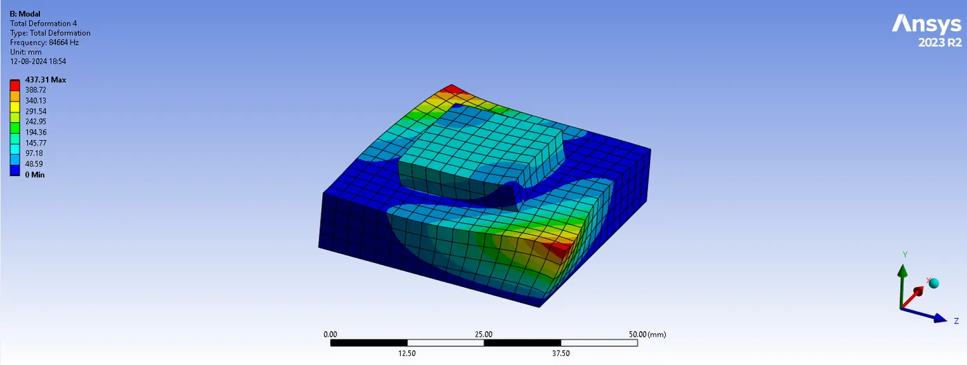
Figure. 17 Mode 4
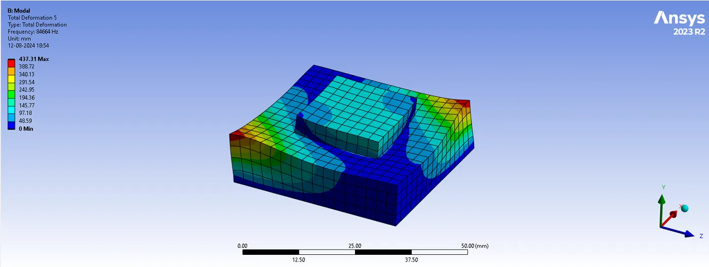
Figure. 18 Mode 5
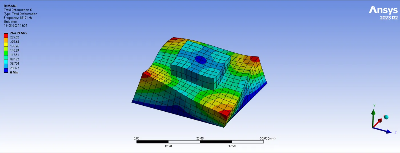
Figure. 19 Mode 6
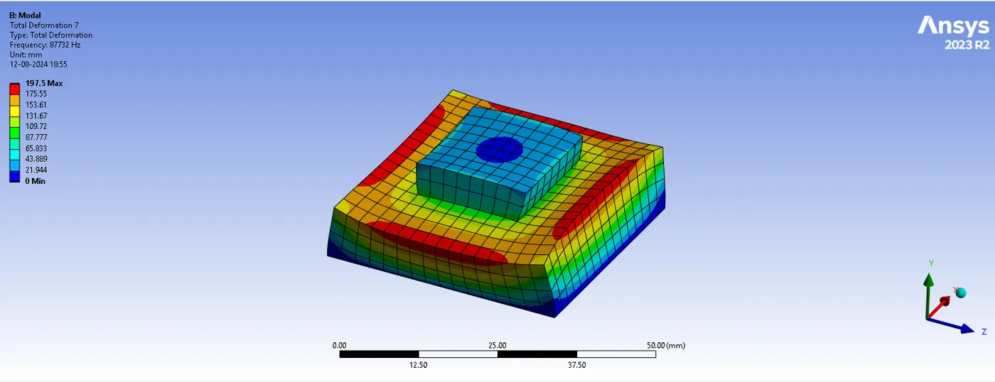
Figure. 20 Mode 7
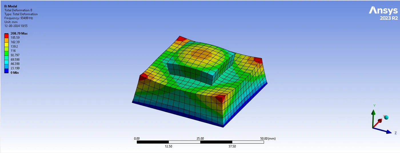
Figure. 21 Mode 8
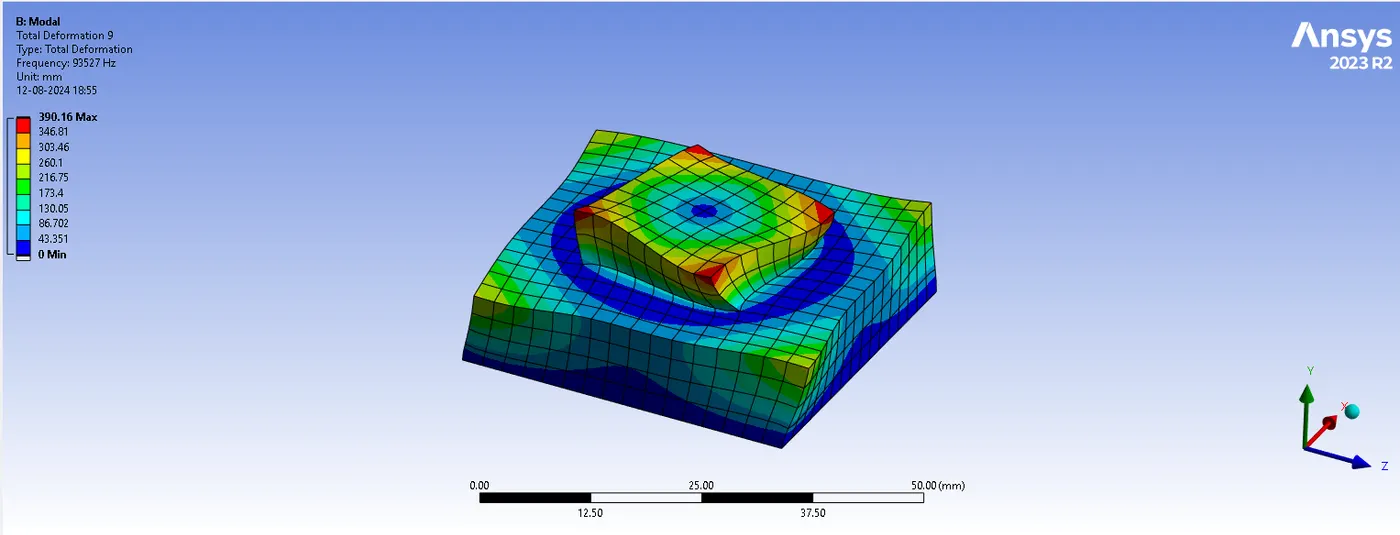
Figure. 22 Mode 9
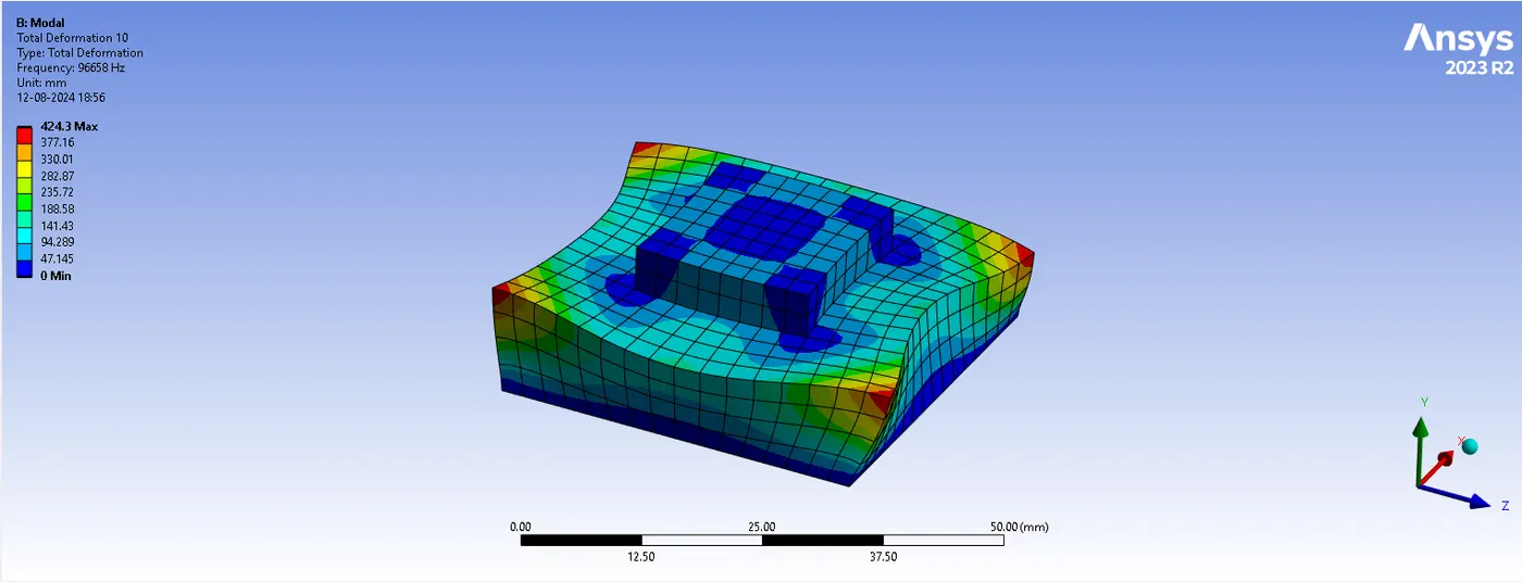
Figure. 23 Mode 10
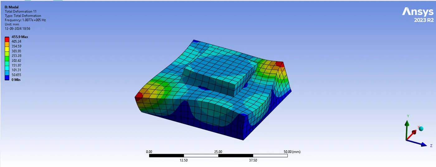
Figure. 24 Mode 11
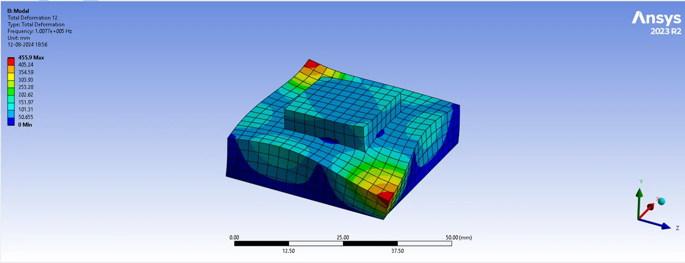
Figure. 25 Mode 12
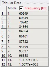
Figure. 26 Model results
Inference
The model analysis is done for 12 modes and similar frequencies values have been observed from the obtained model results. This is due to the similarity in the model, i.e, : the 1,2 - 4,5 - 11,12 modes are acting diagonally to this planar symmetry model (X,Y plane), which is the reason for the similar frequency values.