Week 2 Railwheel and Track
STATIC STRUCTURAL ANALYSIS ON THE RAILWHEEL AND TRACK SETUP
Objective
Case 1:
To simulate the Railwheel and track for their Total Deformation, Equivalent stress, and Life under both the given loads (100 KN & 500 KN ).
Case 2 :
To Implement a User-defined result and to calculate the Total Deformation from this result and to check if it is the same as that obtained by the in-built result by ANSYS for a load of 100 KN.
Material data
Figure. 1 shows the structural steel's properties in Ansys Workbench engineering data. It was used as the bevel gear model's material input.
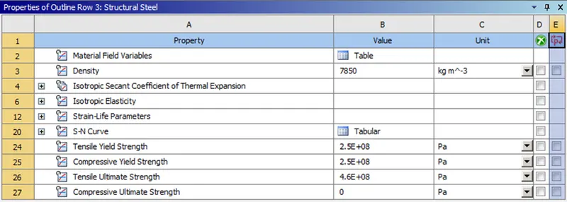
Figure. 1 Structural steel Engineering data
Model Geometry
Figure. 2 shows the imported given Railwheel and track model in the mechanical modular.
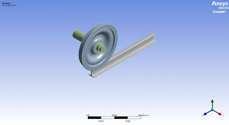
Figure. 2 Railwheel and track model
Contact and Target faces
Figure. 3 illustrates the contact and target faces of the Railwheel and track. In which the wheel is assigned as “Contact Bodies” and the rail is assigned as “Target Bodies” and this is met to be “Frictional”
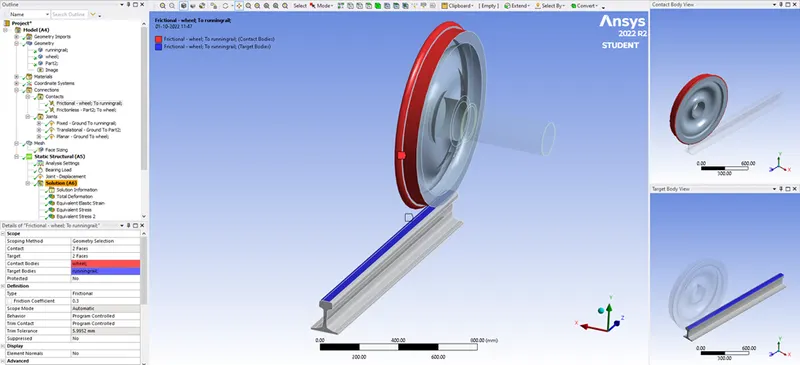
Figure. 3 Frictional- Wheel to running rail
Figure. 4 illustrates the contact and target faces of the Railwheel and axle (“Part 2”) . In which the wheel is assigned as “Contact Bodies” and the axle is assigned as “Target Bodies” and this is met to be “Frictionless”
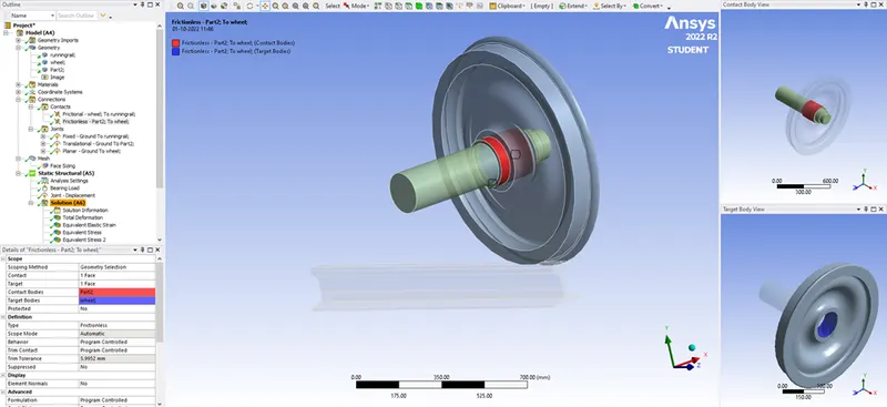
Figure. 4 Frictionless - axle to the wheel
Joint Connections
Figure. 5 illustrates the Fixed connections of the track in which both the side faces are fixed.
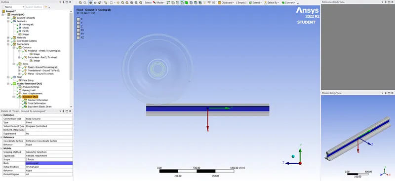
Figure. 5 Fixed - Ground to the track
Figure. 6 illustrates the Translational connection of the axle in which axis was corrected in the direction of wheel motion.
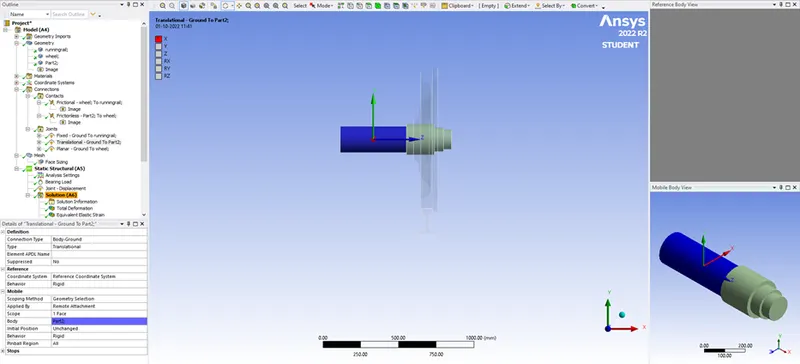
Figure. 6 Translational - Ground to the Axle
Figure. 7 illustrates the planar connection of the Wheel.
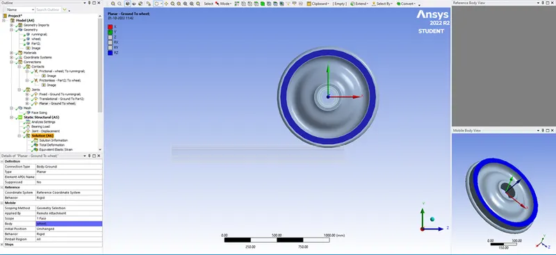
Figure. 7 Planar - Ground to the Wheel.
Meshing
This meshging has been in two level initially with 50 mm meshing size is carried, after that all the 3 faces (Track uper face, Wheel running face and Adjustment face of wheel running face) has been sized with a mesh size of 35mm. Figure. 8 shows the meshed model of Railwheel and track model.
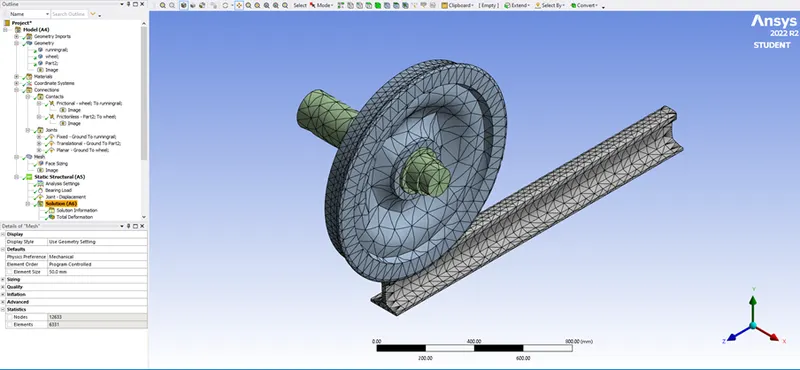
Figure. 8 Meshed Railwheel and track model
Bearing load
Figure. 9 illustrates the bearing load of the Wheel. Since the load act in the inner face of the wheel hole, the inner face of the wheel hole is loaded with 100 KN and in order to view the loading section the Axle is hidden with the “hide body” command
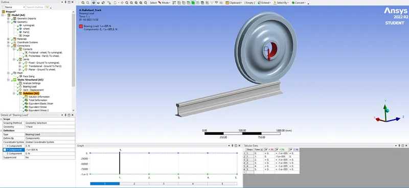
Figure. 9 Bearing load of the Wheel
Joint displacement
Figure. 10 illustrates Joint displacement of the wheel on track since the displacement is for 500 mm and the number of cycles are assigned as 5 steps in the analysis setting, Each steps will be added 100 mm with the previous one to achieve total 500 mm.
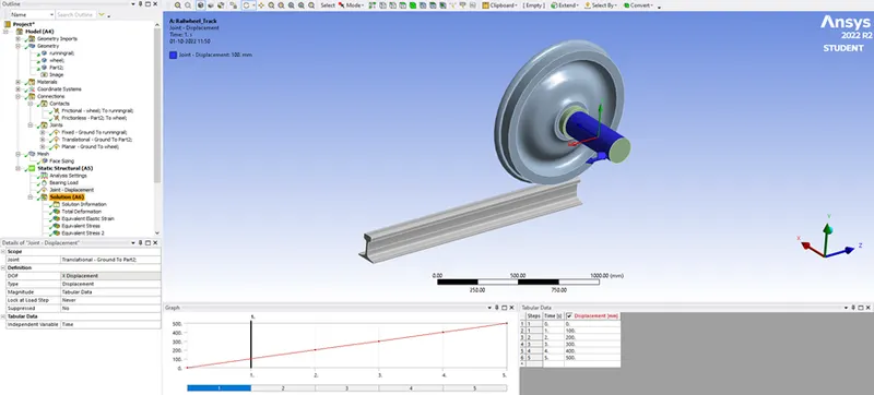
Figure. 10 Joint displacement of the Wheel
Simulation Results
Case 1:
Total Deformation
Figure 11. shows the Total deformation of the Railwheel and track model at 100 KN
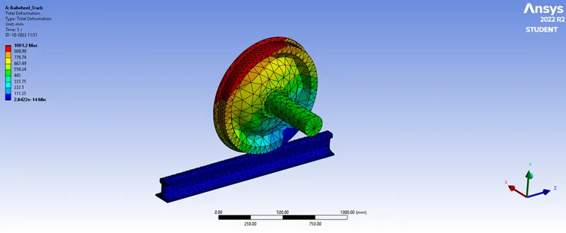
Figure 11. Total Deformation at 100 KN Load
Equivalent Stress
Figure 12. shows the Equivalent Stress of the Railwheel and track model at 100 KN
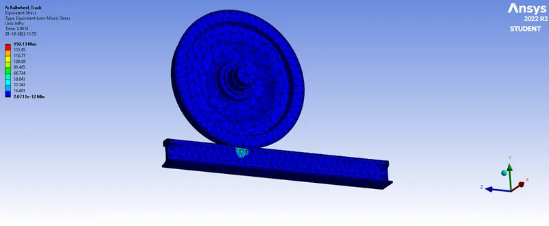
Figure 12. Equivalent Stress at 100 KN Load
Life Cycle
Figure 13. shows the Life Cycle of Railwheel at 100 KN
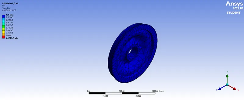
Figure 13. Life Cycle of Railwheel at 100 KN Load
Figure 14. shows the Life Cycle of track at 100 KN
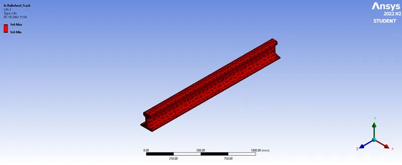
Figure 14. Life Cycle of track at 100 KN Load
Figure 15. shows the Life Cycle of the axle at 100 KN
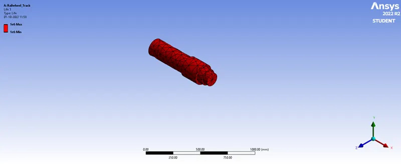
Figure 15. Life Cycle of the axle at 100 K N Load
Total Deformation
Figure 16. shows the Total deformation of the Railwheel and track model at 500 KN
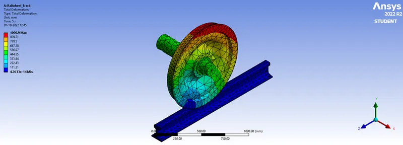
Figure 16. Total Deformation at 500 KN Load
Equivalent Stress
Figure 17. shows the Equivalent Stress of the Railwheel and track model at 500 KN
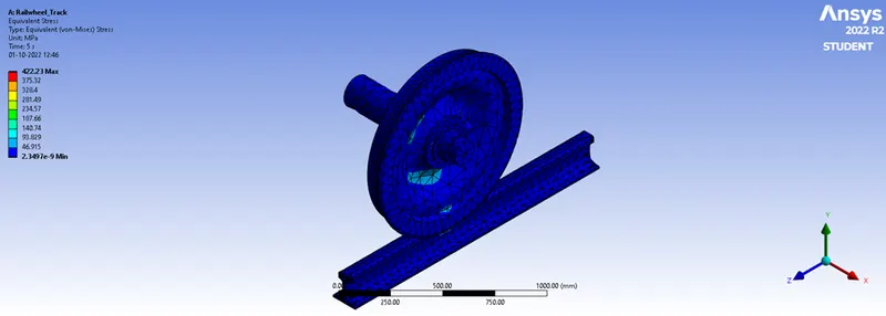
Figure 17. Equivalent Stress at 500 KN Load
Life Cycle
Figure 18. shows the Life Cycle of Railwheel at 500 KN
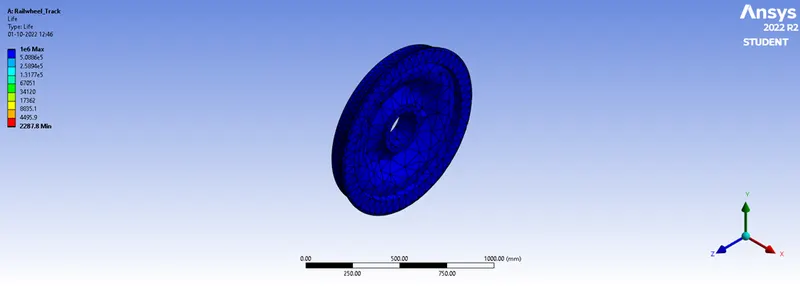
Figure 18. Life Cycle of Railwheel at 500 K N Load
Figure 19. shows the Life Cycle of track at 500 KN
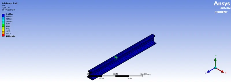
Figure 19. Life Cycle of track at 500 KN Load
Figure 20. shows the Life Cycle of axle at 500 KN
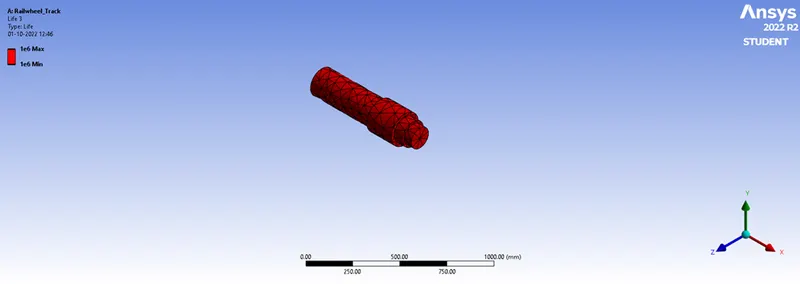
Figure 20. Life Cycle of axle at 500 KN Load
Case 2:
Figure 21. shows the Total Deformation at 100 KN from User-defined results
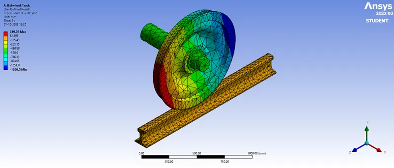
Figure 21. Total Deformation at 100 KN from User-defined results
Figure 22. shows the Total Deformation at 500 KN from User-defined results
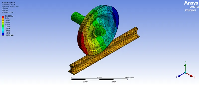
Figure 22. Total Deformation at 500 KN from User-defined results
Comparison of result
Case 1:
|
Bearing load |
||
|
100 KN |
500 KN |
|
|
Total Deformation (Minimum) |
2.8422e-014 mm |
4.2633e-014 mm |
|
Total Deformation (Maximum) |
1001.2 mm |
1000.9 mm |
|
Equivalent Stress (Minimum) |
2.0711e-12 Mpa |
2.3497e-9 Mpa |
|
Equivalent Stress (Maximum) |
150.13 |
422.23 Mpa |
Case 2:
|
Bearing load |
Total Deformation (Maximum) |
Total Deformation from User-defined results (Maximum) |
|
100 KN |
1001.2 mm |
210.02 |
|
500 KN |
1000.9 mm |
209.13 |
Conclusion
- We can observe significant increases in Stress and deformation from comparison results.
- User Defined results are different from inbuilt results in both cases but the range of these results are relatable with the minimum and maximum deformation in their cases separately in a ratio i.e, the difference between maximum deformation and minimum deformation is approximately 1mm in both User Defined and inbuilt results.
- We are aware that structural steel has a 250 Mpa tensile yield strength. Therefore, stress has achieved its maximum level of 422.23 Mpa under 500 KN loads. Plastic deformation will therefore occur, as well as permanent deformation.
- As per the results, we can see that fatigue life in both 100 KN loads and 500 KN loads is a maximum of 1e6 cycles for wheel, track, and axel in the model. Within this cycle, the axle has become unsuitable in both cases hence we should avoid higher loads for safety purposes.