Week 2 Bevel Gear Challenge
STATIC STRUCTURAL ANALYSIS ON BEVEL GEAR IN GRID DEPENDENCY TEST APPROACH
Objective
- To Carry out a static structural analysis to find out Equivalent stress, Total deformation, and Equivalent elastic strain.
- To Use three different sizes of mesh (4, 5, and 6) to perform the grid dependency test.
- To Compare the three results on the basis of the solution.
Grid dependence test
In general, this approach is adapted to find the mesh which is good enough for the analysis. Mesh density is a crucial measure for regulating precision (element type and shape also affect accuracy). A high-density mesh will result in highly accurate results provided there are no singularities. However, if a mesh is excessively dense, it will consume a lot of memory and take a long time to run, especially for multiple-iteration runs, which are characteristic of nonlinear and transient analysis.
The calculation should get closer to the right result as the mesh size gets smaller. How many elements are necessary in a model to ensure that the outcomes of the analysis are unaffected by changing the mesh size is determined by mesh convergence. With shrinking element size, system reaction (stress, deformation) will converge to a repeatable solution. We have utilized three distinct mesh sizes in this instance: coarse, medium, and finer mesh. With the use of this analysis, we can ascertain the precise method for reducing mesh size when a solution for the given shape, a bevel gear, converges.
Material data
Figure. 1 shows the structural steel's properties in Ansys Workbench engineering data. It was used as the bevel gear model's material input.
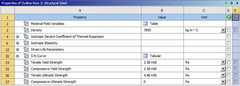
Figure. 1 Structural steel Engineering data
Reduction of Model Geometry
Figure. 2 shows the given model and Figure. 3 shows the reduced model. This reduction was performed to minimize the meshing elements or meshing nodes
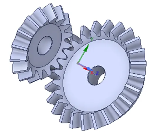
Figure. 2 Given the bevel gear model
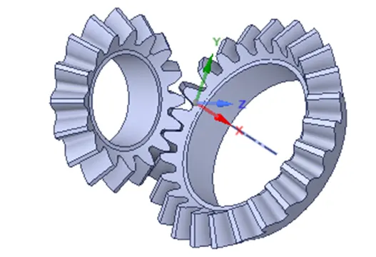
Figure. 3 Reduced bevel gear model
Contact and Target faces
Small gear and big gear are the new names in this gear model. Figure. 4 illustrates the contact and target faces of the small and big gear's teeth. The small gear has 16 tooth faces, while the big gear has 24.
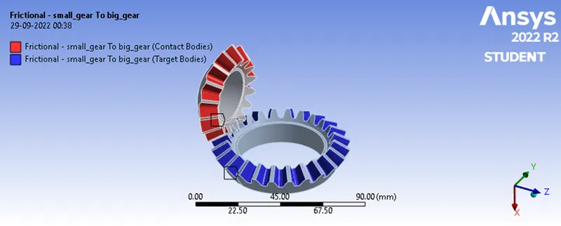
Figure. 4 Contact and Target faces
Meshing
This meshing has been in two-level initially with default meshing size is carried, after that, all the 40 faces of the gear tooth faces has been sized with a mesh size of 1.75mm. Figure. 5 shows the meshed model of bevel gear.
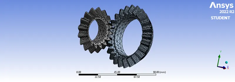
Figure. 5 Meshed bevel gear model
Analysis setting (Joint loads – Rotation, Moment)
The joint loads have been set for 6 number of steps and the large deflection is turned “on” then revolute joint of "Big_gear" is assigned of type “Moment” magnitude from “Tabular Data”. The assigned Joint loads – Moment Analysis setting has been shown in Figure 6.
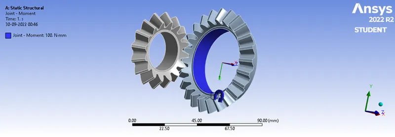
Figure 6. Joint loads – Moment Analysis setting
The revolute joint of "Small_gear" is assigned of type “Rotation” magnitude from “Tabular Data”. The assigned Joint loads – Rotation Analysis setting has been shown in Figure 7.
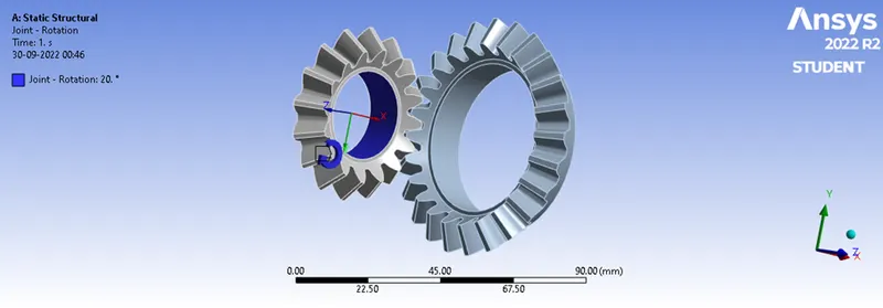
Figure 7. Joint loads – Rotation Analysis setting
Simulations results
Equivalent Stress
Figure 8. shows the Equivalent stress of the bevel gear model
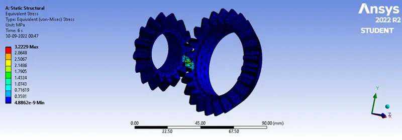
Figure 8. Equivalent stress of the bevel gear model
Total Deformation
Figure 9. shows the Total deformation of the bevel gear model
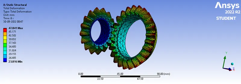
Figure 9. Total deformation of the bevel gear model
Equivalent Elastic Strain
Figure 10. shows the Equivalent Elastic Strain of the bevel gear model
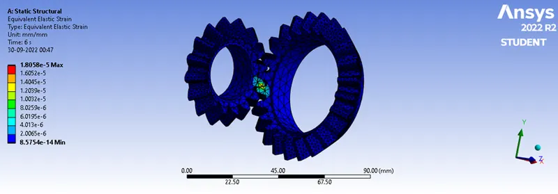
Figure 10. Equivalent Elastic Strain of the bevel gear model
Note: The meshing condition described under the heading "Meshing" is what produced the findings seen above.
Grid Dependency ( Parametric analysis for each solution for given three mesh sizes)
Grid dependency test was carried out by initiating “Parameter Set” by checking up the check box of the desired outcomes, Since our need outcomes are Equivalent stress, Total deformation, and Equivalent elastic strain the results are updated for all points with assigned three(4,5,6) mesh sizes in the “Table of Design Points”. Outline of All Parameters is shown in Figure. 11. Table of Design Points is shown in Figure. 12.
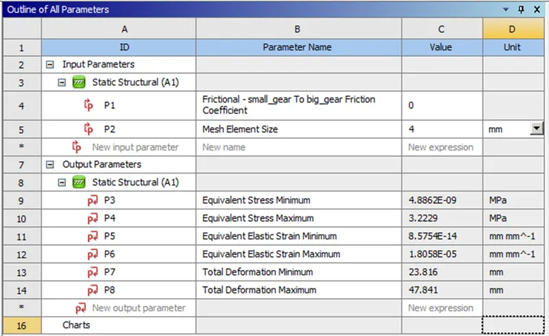
Figure. 11 Outline of all parameters

Figure. 12 Table of Design Points
Results
|
Mesh Element Size |
Equivalent Stress Minimum (MPa) |
Equivalent Stress Maximum (MPa) |
|
4 |
4.8862E-09 |
3.2228 |
|
5 |
7.7299E-09 |
2.7067 |
|
6 |
6.2313E-09 |
3.1327 |
|
Mesh Element Size |
Equivalent Elastic Strain Minimum (mm^-1) |
Equivalent Elastic Strain Maximum (mm^-1) |
|
4 |
8.5754E-14 |
1.8058E-05 |
|
5 |
8.6601E-14 |
1.6233E-05 |
|
6 |
7.6388E-14 |
1.6350E-05 |
|
Mesh Element Size |
Total Deformation Minimum (mm) |
Total Deformation Maximum (mm) |
|
4 |
23.8156 |
47.8407 |
|
5 |
23.8156 |
47.8407 |
|
6 |
23.8156 |
47.8407 |
Conclusion
- A successful grid dependency test was carried out with three mesh sizes, each mesh size is increased by 1mm throughout each cycle.
- The 4 mm mesh size produces accurate results, however the 5 mm and 6 mm mesh sizes don't produce the intended outcomes as well.
- We observed that, at the longer computation time, the answer will be more accurate and with the finer mesh size the outcomes will be accurate.