Week 7-Long Piston With Cam
Transient structural Long Piston With Cam
Objective
To perform a transient structural analysis on a piston and cam mechanism model in Ansys Workbench for three different frictional cases.
Case 1: To perform with Frictionaless Contact
Case 2: To perform with Frictional Contact with Friction coefficient of 0.1
Case 3: To perform with Frictional Contact with Friction coefficient of 0.2
To find out:
- Equivalent Stress, Directional Deformation and Equivalent Elastic Strain for all three cases
- Inference as to why the results vary between cases
Material data
Figure. 1 shows the structural steel's properties in Ansys Workbench engineering data. It was used as the Long Piston With Cam model's material input expect the wire.
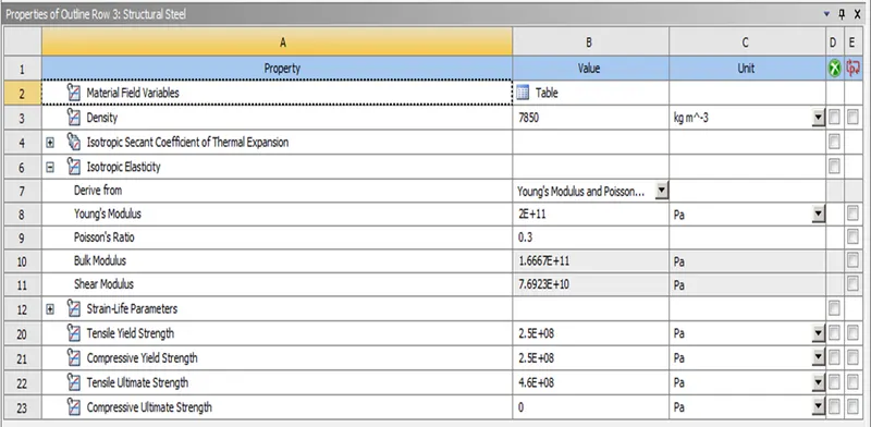
Figure. 1 Structural steel Engineering data.
Model Geometry
Figure. 2 shows the imported given Long Piston With Cam model in the mechanical modular.
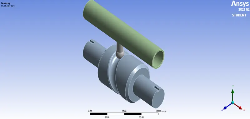
Figure. 2 Long Piston With Cam model
Figure. 3 illustrates that the Stiffness Behaviour of the Cam and Barrel is assigned to be Rigid since we are considering the motions of the Piston which is meant to be flexible.
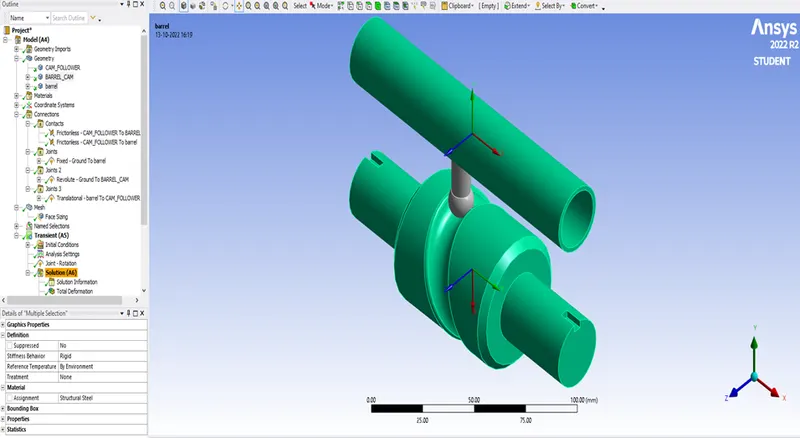
Figure. 3 Stiffness Behaviour of the Cam and Barrel
Connections
Figure. 4 illustrates the connections between the Cam and the Piston. The Piston faces is assigned as the ‘Contact bodies’ and the Cam faces is assigned as the ‘Target bodies’. Similarly Figure. 5 illustrates the connections between the Piston and the Barrel. The Piston faces is assigned as ‘Contact bodies’ and the Barrel faces is assigned as the ‘Target bodies’.
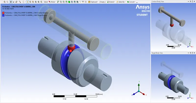
Figure 4 Frictionless- Piston to Cam
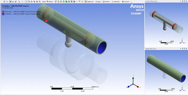
Figure 5 Frictionless-Piston to Barrel
Joints
Figure. 6 illustrates Fixed joint of the Barrel. Figure. 7 illustrates the Revolute joint of the Cam. Figure. 8 illustrates the translational joint of the Piston. Then the first 2 joints don’t need a reference body it is Ground referenced at the same time the Translational joint takes Barrel as the reference body, which has Rigid behaviour.
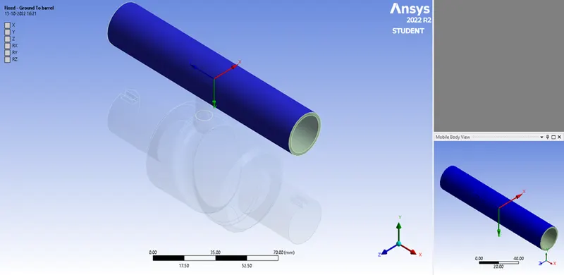
Figure. 6 Fixed-Ground to Barrel
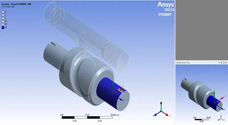
Figure. 7 Revolute-Ground to Cam
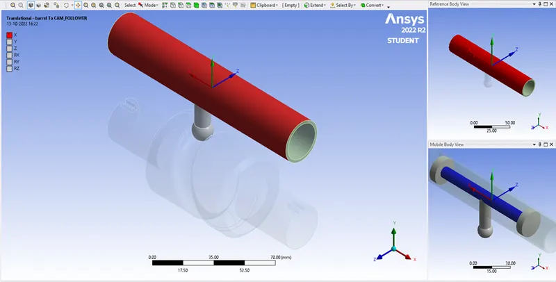
Figure. 8 Translational-Piston to Barrel
Meshing
The model is initially Default meshed with no Adaptive sizing and the Face sizing has been given to the contact faces of Cam and the Piston with sizing of 2.5 mm as shown in Figure. 9. The overall meshed model is shown in Figure. 10.
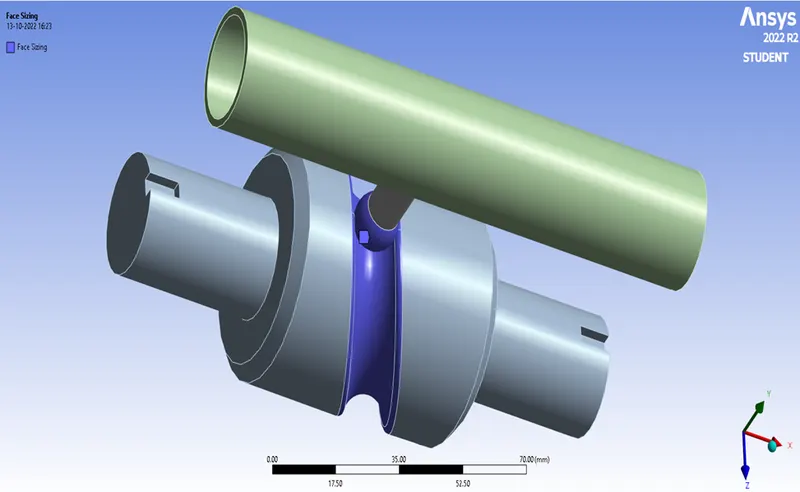
Figure. 9 Face sizing
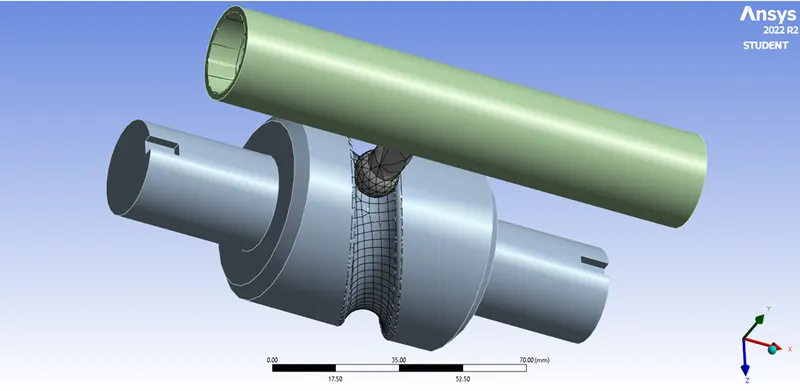
Figure. 10 Overall meshed model
Joint Rotation
The cam motion controls the piston movement in the Barrel. Hence the revolute joint is given with the rotation degree of freedom (DOF) as shown in Figure. 11.
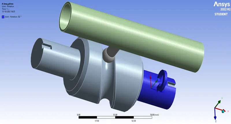
Figure. 11 Barrel joint rotation
Simulation Results
Case 1:
Equivalent Stress
Figure. 12 illustrates the Frictionless Equivalent Stress of the Model
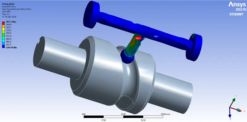
Figure. 12 Frictionless Equivalent Stress
Directional Deformation
Figure. 13 illustrates the Frictionless Directional Deformation of the Model
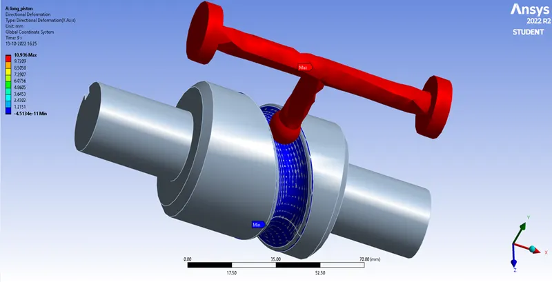
Figure. 13 Frictionless Directional Deformation
Equivalent Elastic Strain
Figure. 14 illustrates the Frictionless Equivalent Elastic Strain of the Model
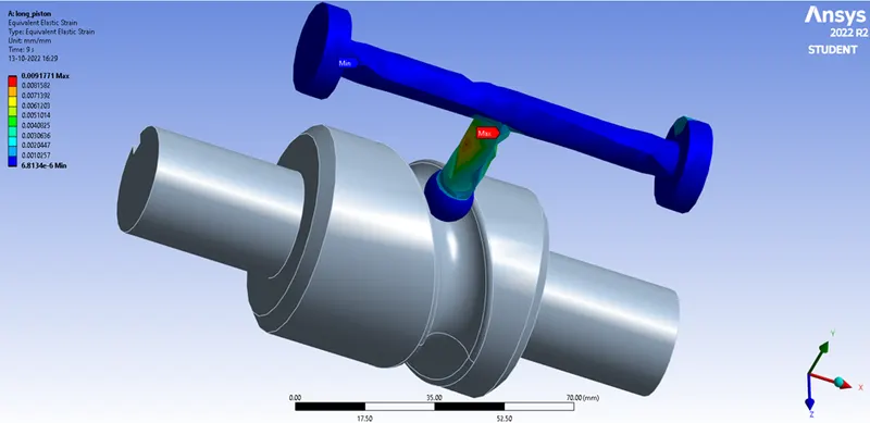
Figure. 14 Frictionless Equivalent Elastic Strain
Case 2:
Equivalent Stress
Figure. 15 illustrates the Frictional (Friction coefficient = 0.1) Equivalent Stress of the Model
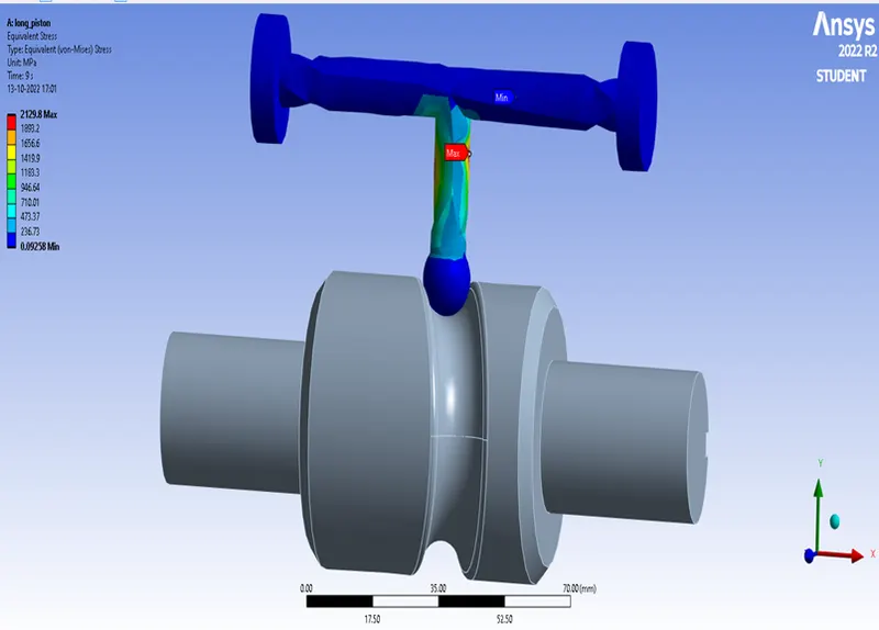
Figure. 15 Frictional Equivalent Stress (Friction coefficient = 0.1)
Directional Deformation
Figure. 16 illustrates the Frictional (Friction coefficient = 0.1) Directional Deformation of the Model
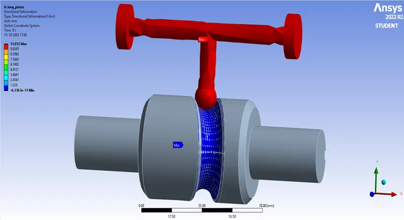
Figure. 16 Frictionl Directional Deformation (Friction coefficient = 0.1)
Equivalent Elastic Strain
Figure. 17 illustrates the Frictional (Friction coefficient = 0.1) Equivalent Elastic Strain of the Model
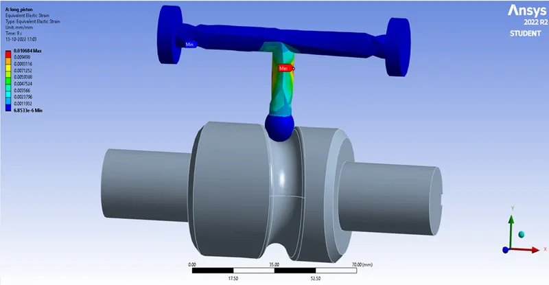
Figure. 17 Frictionl Equivalent Elastic Strain (Friction coefficient = 0.1)
Case 3
Equivalent Stress
Figure. 18 illustrates the Frictional (Friction coefficient = 0.2) Equivalent Stress of the Model
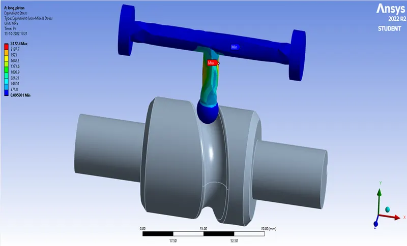
Figure. 18 Frictional Equivalent Stress (Friction coefficient = 0.2)
Directional Deformation
Figure. 19 illustrates the Frictional (Friction coefficient = 0.2) Directional Deformation of the Model
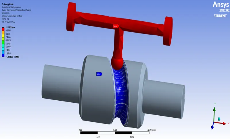
Figure. 19 Frictional Directional Deformation (Friction coefficient = 0.2)
Equivalent Elastic Strain
Figure. 20 illustrates the Frictional (Friction coefficient = 0.2) Equivalent Elastic Strain of the Model
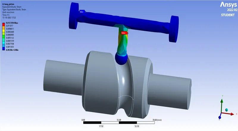
Figure. 20 Frictionl Equivalent Elastic Strain (Friction coefficient = 0.2)
Comparison of Case 1, Case 2 & Case 3
|
Parameters |
Case 1 |
Case 2 |
Case 3 |
|
Maximum Equivalent Stress |
1827.7 MPa |
2129.8 MPa |
2472.4 MPa |
|
Maximum Directional Deformation |
10.936 mm |
11.052 mm |
11.183 mm |
|
Maximum Equivalent Elastic Strain |
0.0091 mm |
0.0106 mm |
0.0123 mm |
Conclusion
- All Case Maximum results have shown incremental values with the previous Case. This shows friction as the major effect on all the Cases, i.e. as friction coefficient increases Equivalent Stress, Directional Deformation and Equivalent Elastic Strain values increases.
- This makes them directionally proportionate to each other because more force is needed to overcome the friction.