Project-2-Meshing of Door Inner Panel Challenge
Meshing of Door Inner Panel
Objective:
To mesh the Inner Door Panel model with provide quality parameters and assign thickness.
The given Quality Criteria
Target Element Length = 4 Units
|
S.N |
Quality Criteria |
Value |
|
1 |
Aspect Ratio |
5 |
|
2 |
Skewness |
45 |
|
3 |
Warping |
15 |
|
4 |
Taper |
0.5 |
|
5 |
Min. Length |
2 Units |
|
6 |
Max. Length |
6 Units |
|
7 |
Min angle Quad |
45 |
|
8 |
Max angle Quad |
135 |
|
9 |
Min angle Tria |
20 |
|
10 |
Max angle Tria |
120 |
|
10 |
Tria % |
10 |
Procedures:
Geometry Import
The given the hm file is Imported. After the geometry has been imported, the model is next processed for midsurface extraction after being checked for any missing surfaces or triple cons. The geometry is divided in to two component (Top and Bottom) for proper manual midsuface extract as shown in Figure 1.
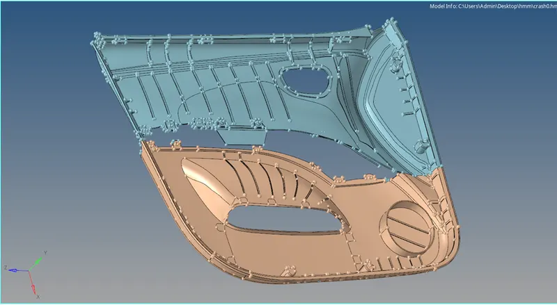
Figure 1: Inner Door Panel model
Quality Criteria
The quality criteria has been assigned as per the given data by Preference + Criteria File Settings. In the Criteria Editor dialog box as shown in Figure 2.
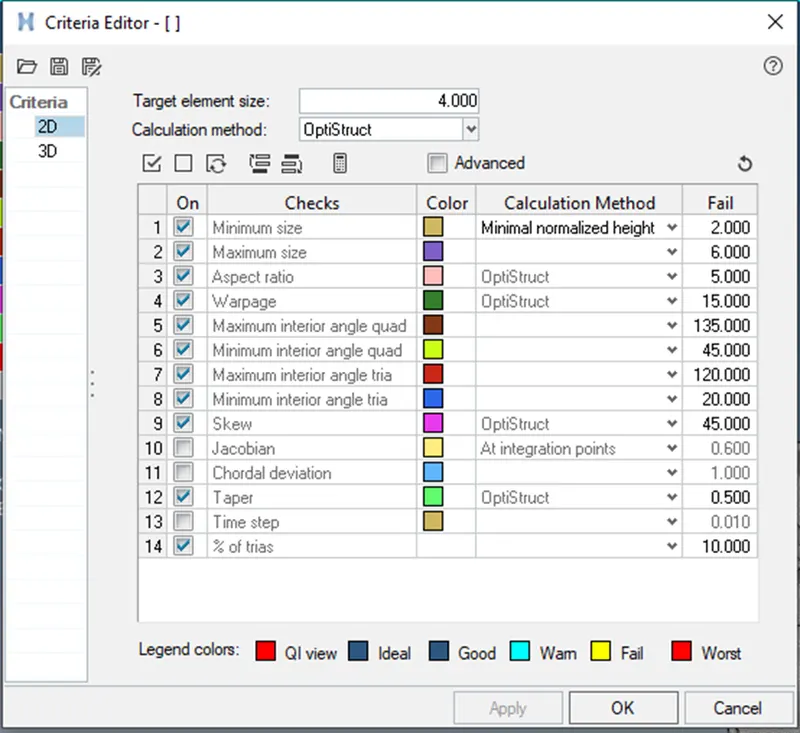
Figure 2: Criteria Editor dialog box
Extracted Midsurface
Midsurface can be extracted by Offset
Command: Geometry + Surface edit + Offset surface + select the surface + assign mid value of surface offset + extract.
Geomentry Cleanup
Clean the geometry by the use of Quick edit option in the geometry then use the Trim option in Surface edit to connect and delete the mismatched surface. Use washer split, split surf-node, split surf-line, release point, project point, replace point, & toggle edge features for apt surface for mesh generation as shown in Figure 3 & 4.
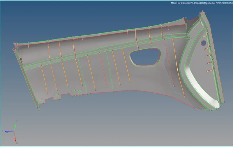
Figure 3: Extracted Top Midsurface
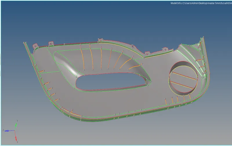
Figure 4: Extracted BottomMidsurface
Component Mesh
Generate the mesh of element size as 5mm with mixed element type.
Command: 2D + Automesh + All Surface + Mixed element + Create
Mesh Quality
The meshed component is re meshed to avoid poor mesh elements with rebuild mesh option on localizied element selection.then with the help of Clean up tools the proper mesh quality is achieved, i.e. element optimize, place node, node optimize, split quad element, & drag tria element as shown in Figure 5 & 6.
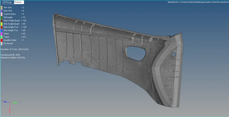
Figure 5: Top Midsurface with Mesh Quality
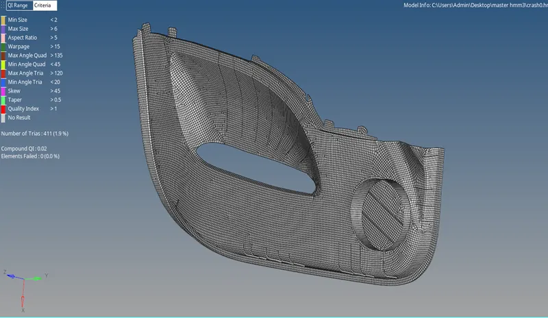
Figure 6: Midsurface with Mesh Quality
Assigning thickness
To properly thickness the elements, we must first add properties and modify the thickness value at the property. then you must modify the thickness value for this property. Thickness value for a property is located under "T" value under the property tab.
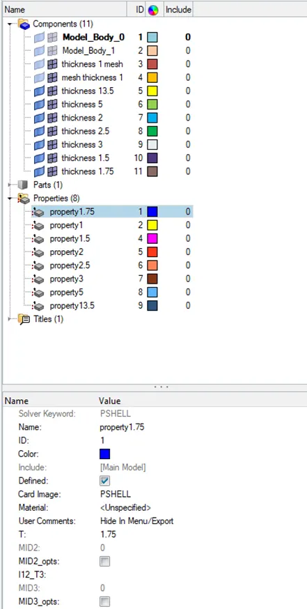
Figure 7: Created components & properties
Since the total component has 8 different thickness we have created 8 components and corresponding properties. Then we must alter the value of "T" to 1, 1.5, 1.75, 2, 2.5, 3, 5,& 13.5 mm. The property must be assigned to the component after it has been constructed in order for it to appear on the elements. Simply pick "Assign" from the context menu when doing a right-click on the component to accomplish this. The assigned thickness is shown in Figure 8.
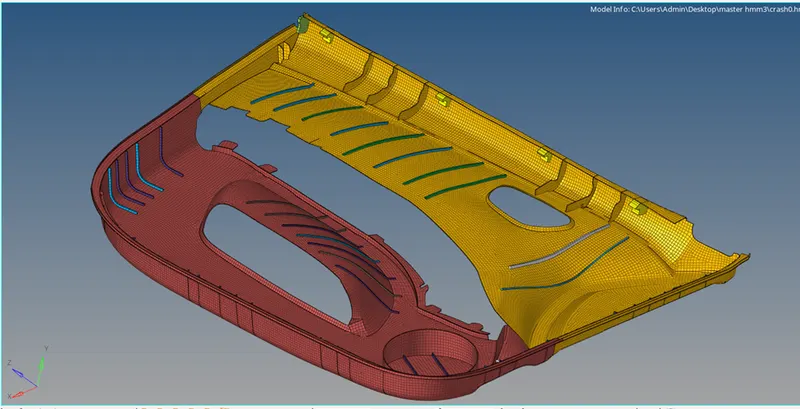
Figure 8: Mesh elements with Assigned Thickness
Conclusion
Mid-surface is extracted from the provided model, and mesh is created in accordance with the provided quality criteria then thickness is assigned.