Week 6-Meshing of Hood Challenge
AIM:
Follow the below-mentioned quality criteria, mesh the component given below and assign thickness:
Target Element Length = 5 Units
| S.N | Quality Criteria | Value |
| 1 | Aspect Ratio | 5 |
| 2 | Skewness | 45 |
| 3 | Warping | 15 |
| 4 | Taper | 0.5 |
| 5 | Min. Length | 2 Units |
| 6 | Max. Length | 8 Units |
| 7 | Min angle Quad | 45 |
| 8 | Max angle Quad | 135 |
| 9 | Min angle Tria | 20 |
| 10 | Max angle Tria | 120 |
| 10 | Tria % | 10 |
Procedure:
First we are going to import the geometry.
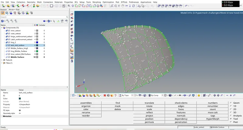
Here we have 4 componet and now we will go for the mid surface extraxtion using geometry>midsurface.
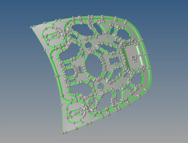
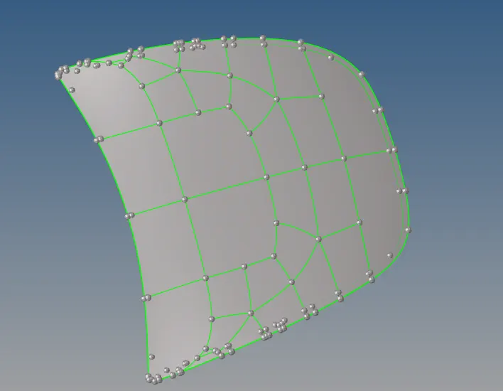
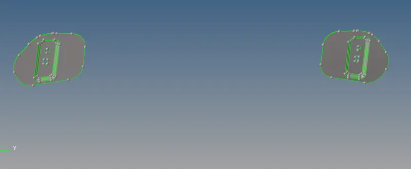
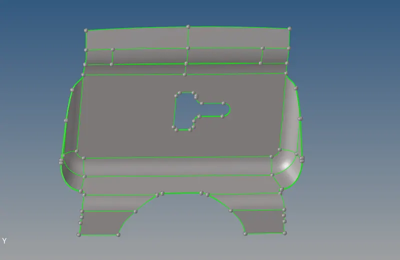
Here we have 4 parts so now we go for midsurfae extraction one by one.
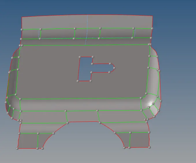
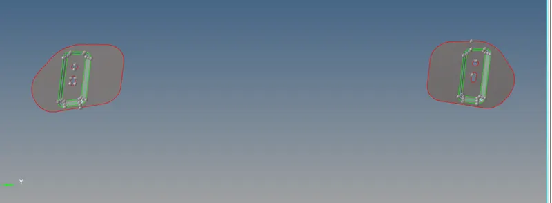
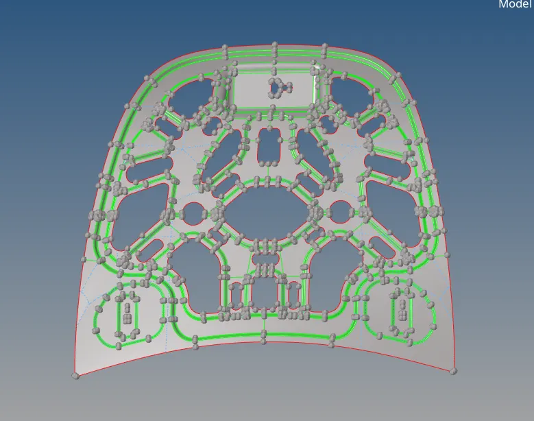
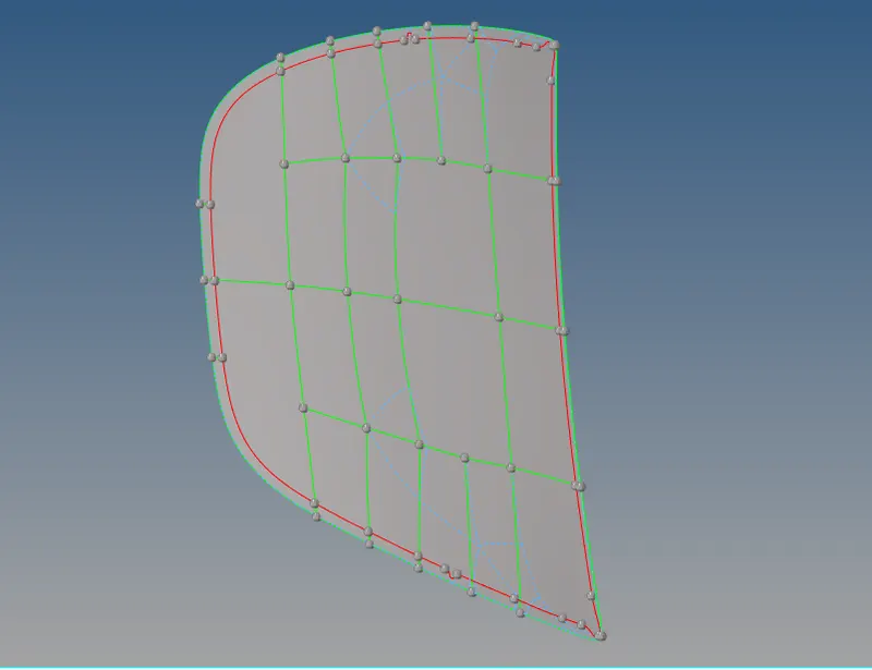
After this i am going for the geometry cleanup and then i go for the meshing so i prefer both at same time meshing as well as geometry cleanup.
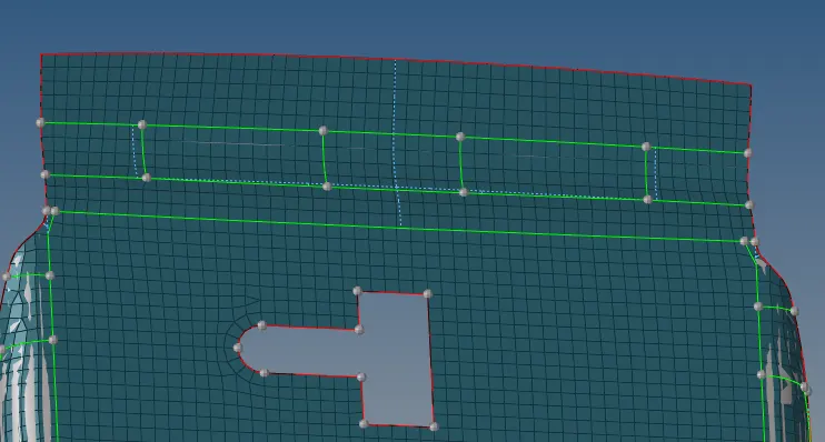
here in the latch part you can see i toggled all the unnessary fillet lines which you can see in the blue dotted line.and after that i do mesh in the whole reason so for that i used toggle optipon in the quick edit option through that we can defeature the unnecessary fillets and also you can join the single edge faces with small tolerance . and also at some place i used add point option in the quick edit and also used split with line for creating cut on surface with node and corresponding line.Also used node to node cut in quick edit for the cut.
After that we have to mesh the surface one by one and clear the quality.So for that we use auto mesh in the 2D or F12.There i ahve to give the target element size as 5unit and mesh the surface .
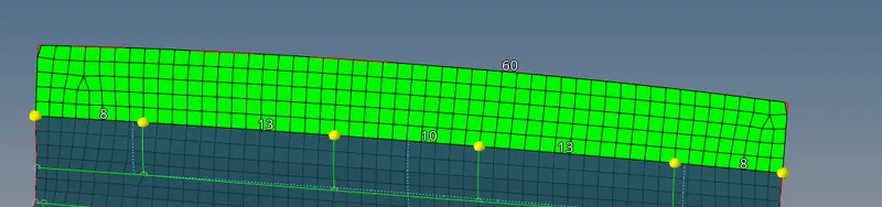
Here in the upper image you can see that in auto mesh we have some trias and it can be avoided by increasing or decreasing the node count by right click and left click.
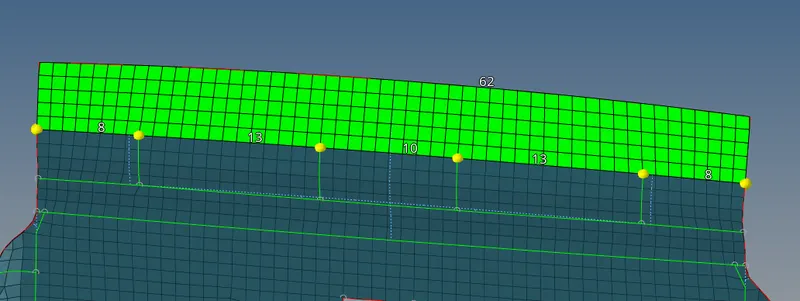
See after increasing the node count that trias are removed into quad as you can see above.
we have another option to get good mesh that is rebuild option inside the 2D mesh inside that we have to put the whole quality criterial as mentioned in the question.
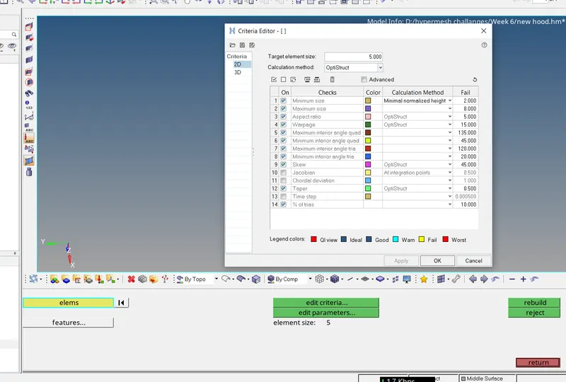
See in this option we have edit criteria and there we have to put all quality criteria.
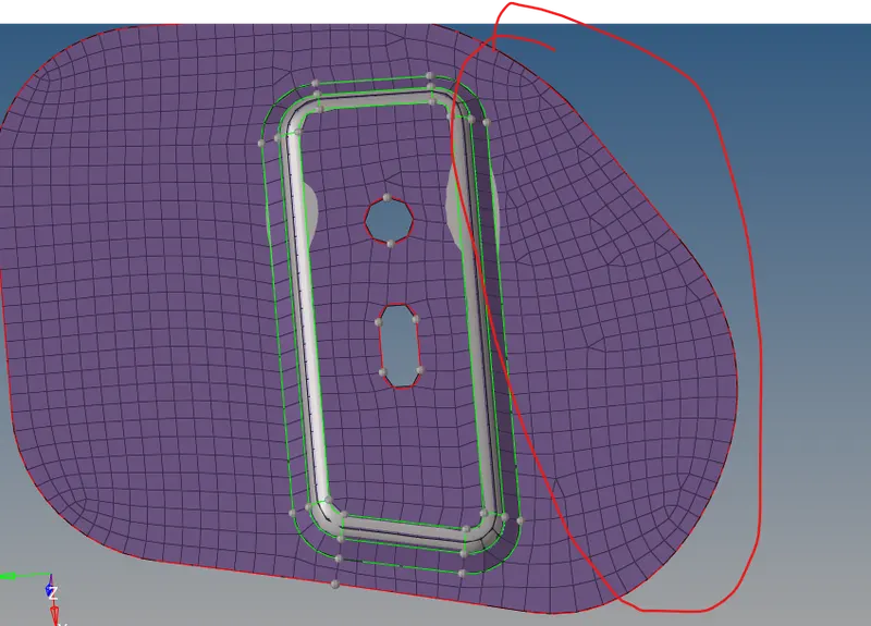
Here in this component it is difficult to get good mesh flow by using increase or decrease node count so here i used rebuilt option and the givn image above is after doing the rebuilt option.
By using all this option i meshed all the parts and one more option i used is Reflect option in the tool for meshing the symetric parts like the inner extract we have similar features on both side as shown below.
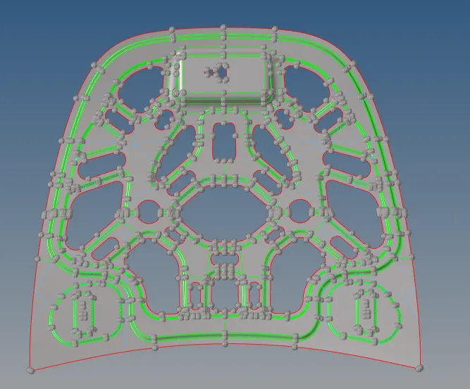
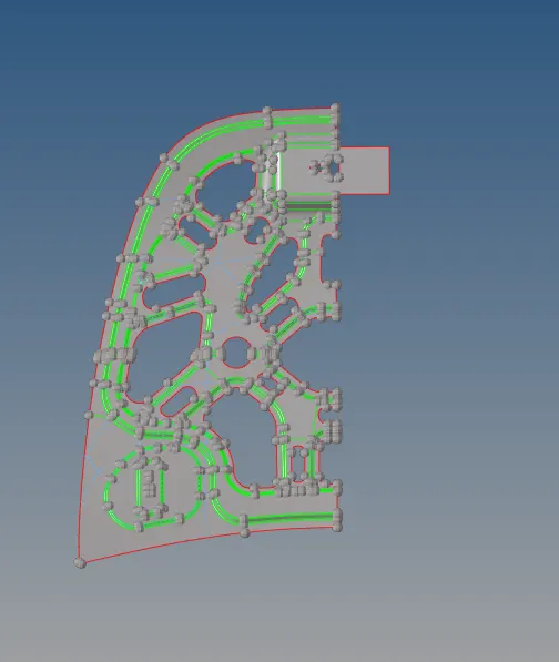
So i deleted the half part and mesh that part after that i reflect that element and the componet to the other symmetric reason,i used the reflect option in tool and then i select the option as component and and select the symmetric part and then select the node vector and the base node then click reflect and the part is made symmetric as previous and use toggle option and do left click to join the component.
In the same way we have to reflect the element or mesh to the other part by selecting the element as the option and select the node vector and base node then click reflect it is reflected.
i had used one more otption to paste all the node of the symetric part so for that we go for edges option inside tool and there we select the whole elemnt and give the tolrance as 0.5 and click the preview equivalance and then all the nodes are highlited which are not pasted and then we have to click equivalence to connect.
In the same way we have to go for the outer hood .
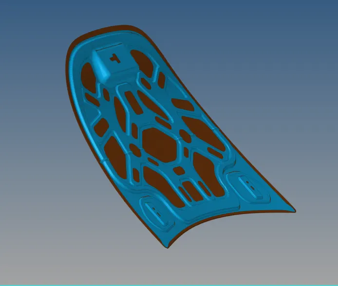
This is the whole mesh now we hav to check the quality for that we have to go in the quality index in the 2D.there we have all the quality criteria already mentioned as we have given in the rebuit option also we can check whethrer it is same as question. so after that we click on the cleanup and used element optimize to clear the quality so that it adjust the mesh and he quality is cleared. Also we have lots of options in that swap edges and split/collaps edge smooth we by using all that option we have to clear the quality .
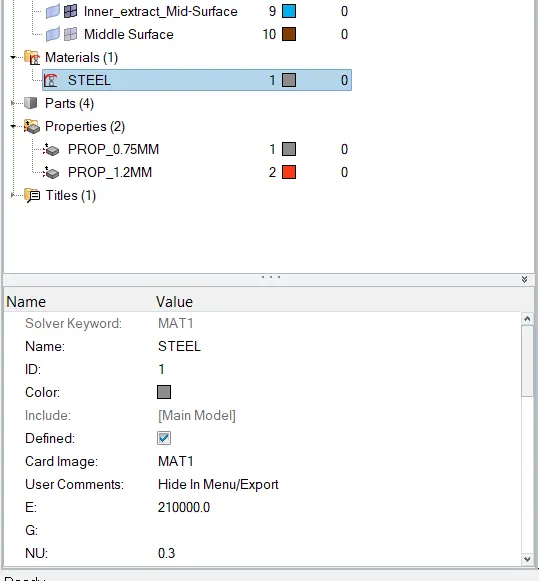
Now after that we have to assign the property and thickness and also material as steel so for that we have lots of ways in the model where all the componets are shown we can assign it from there and also there is a option below the working area we can assign it from there so i made here 2 properties because we have only 2 different thickness and assigned one material as steel. aas you can see in the below image.
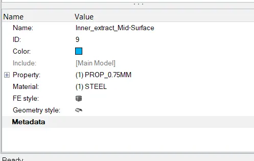
And we have to assign this to the component. As shown below.
After this we will check the edges from the tool is there any free edges in the middle of the component or normals,etc.
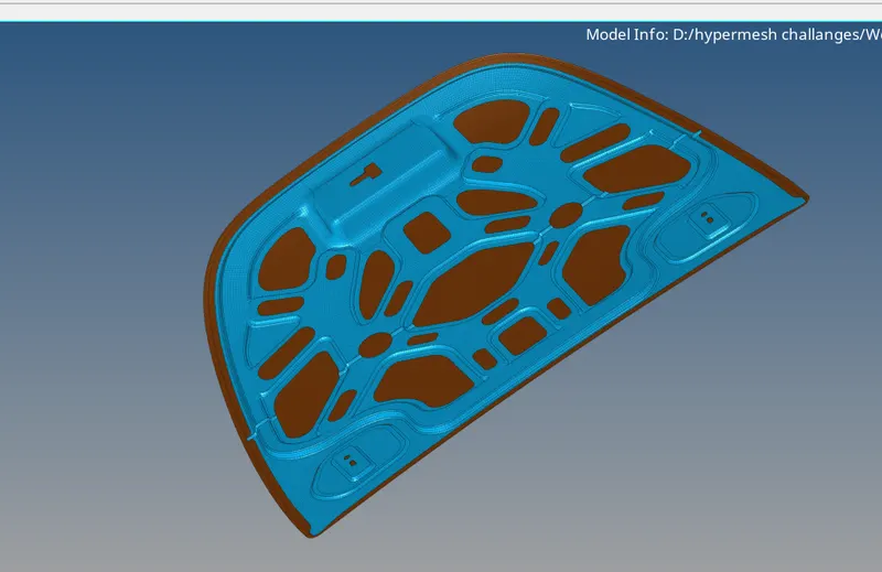
Finally,my model after meshing it looks like as below.
Learning outcome:
- Here we learn the use of rebuilt option,options in quick edit,use of edges options in tool, and also different checks like penetration check,vector check,etc.
Conclusion:
- Here as per the given question i meshed all the different parts of the component and thickness assign to it.