Week -2
AIM: 1. Make a Simulink model of Doorbell using solenoid block.
2. Use a thermistor to sense the temperature of a heater & turn on or turn off the fan as per the condition.
- Block diagram for doorbell.
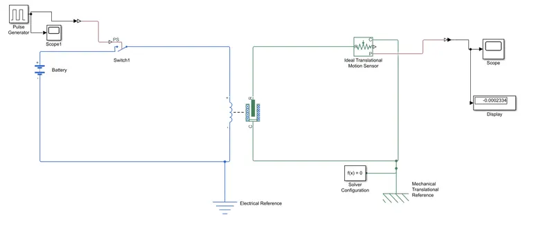
Block diagram explaination:
Here the blocks we use are:
- solenoid
- pulse generator
- Scope
- Switch
- Simulink ps converter
- Ps simulink converter
- Battery
- Electrical referance
- Ideal translational motion sensor
- Display
- Mechanical translational reference
- Solver configuration
EXPLAINATION
- Here we start with the solenoid block one side is electrical part and another side is mechanical.
- In th electrical side we are taking inputs, first we connect battery with pulse generator as the input where we give period as 4,make the pulse width as 50% for the 2 second.
- Now connect the pulse generator to switch through simulink ps converter and connect the electrical referance.
- Now on the mechenical part where the solenoid moves in translational motion there we connect the ideal translational motion sensor second port is connected with the translational reference and one solver confugration is connected with it and another port is connected with output scope through ps simulink converter and one display is connected to se the value of output.
INPUT SCOPE: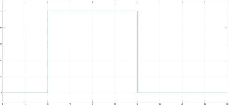
OUTPUT SCOPE: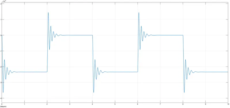
2. Block diagram for thermistor:
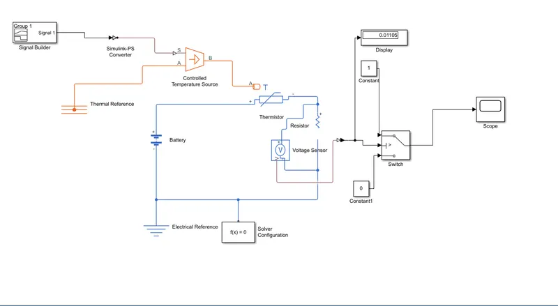
BLOCK EXPLAINATION:
ere the blocks we use are:
- Signal builder
- Ps simulink converter
- Simulink ps converter
- Controlled temperature source
- Thermal referance
- Thermistor
- Battery
- Electrical reference
- Solver configuration
- Resistance
- voltage source
- Switch
- Constant
- Scope
- Display
EXPLAINATION:
- Thermistor input is connected with controlled temperature source and the signal builer as input is given to the controlled temperature source using simulink ps converter.
- the input inside the signal builder is as provided in the question (Temperature source: 20 °C from 0 to 10 seconds, 27 °C from 10 to 30 seconds, 23 °C from 30 to 50 seconds).
- One thermal reference is connected to the Controlled temperature source.
- One port of thermistor is connected with battery,electrical reference and solver configuration is conected with it and now the resistance is connected in series with it and a voltage source is connected in parallel with resistance.
- The reading of voltage is given as input of switch through ps simulink converter,a display is connected to see the reading of voltage.
- now there we have to use the condition as per the question (Fan conditions: ON if the temperature above 25 °C, OFF otherwise) , now first we connect a constant(1 as input) in place of signal builder and run the simulation and cecke the reading of voltage source in the display ans give that value inside the switch input port, again remove that constant block and make it as it was.
- now we have to use two constant block (one is 1 connected to upper port and another is 0 connected to to lower port) to connect to the other 2 port of switch as the output of switch now here we use condition like if the output of voltage source is geater than the input provided inside the switch the switch goes upward port that is 1 and that means fan is on and if it is less than input of switch it goes to down port that is 0 that means off as you can see in the output provided below.
OUTPUT: