Week 8 Worm Gear Challenge
AIM:We will have to perform a transient structural analysis on a worm gear assembly.
Objective:
We will have to perform a transient structural analysis on a worm gear assembly. For the academic version, you need to cut the gear by half so as to bring the model within limits. For the challenge, you have to rotate the worm so as to get to almost end of the half cut and get results for Equivalent stress, Equivalent elastic strain and the total deformation in the model. You can use a finer mesh while performing the challenge and submit a well formatted report with appropriate images.
Theory:
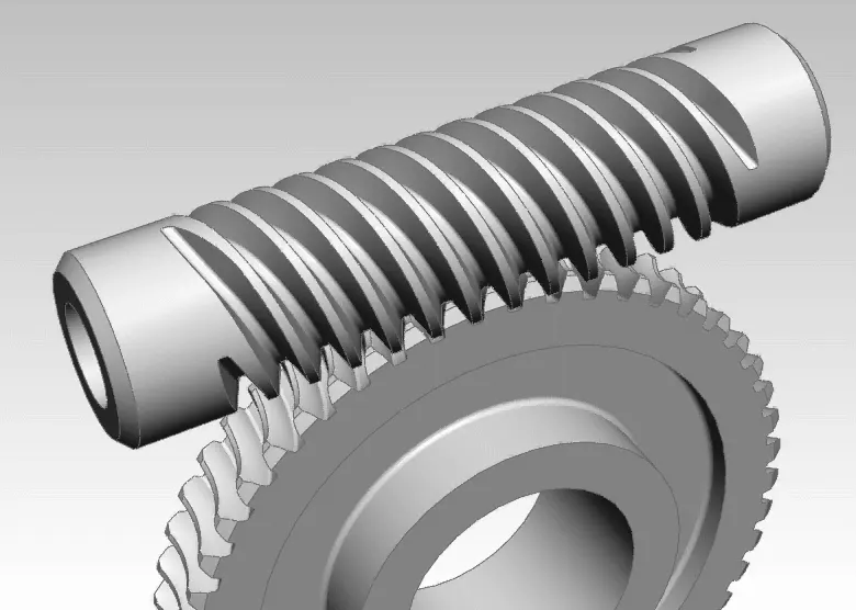
What Is a Worm Gear?
A worm gear is a gear consisting of a shaft with a spiral thread that engages with and drives a toothed wheel. Worm gears are an old style of gear, and a version of one of the six simple machines. Basically, a worm gear is a screw butted up against what looks like a standard spur gear with slightly angled and curved teeth.
It changes the rotational movement by 90 degrees, and the plane of movement also changes due to the position of the worm on the worm wheel (or simply "the wheel"). They are typically comprised of a steel worm and a brass wheel.
How Worm Gears Work
An electric motor or engine applies rotational power via to the worm. The worm rotates against the wheel, and the screw face pushes on the teeth of the wheel. The wheel is pushed against the load.
Procedure:
- Start the ANSYS Workbench and double click on Transient structural and rename it "Womb_gear".
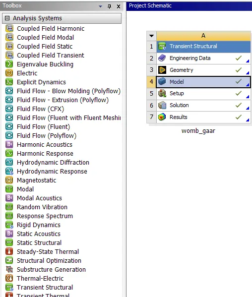
- Now in the engineering data no need to change any thing structural steel is taken as default.
- After that right click on model and import the geometry available in the question,then again double click on the model to edit in spaceclaim as shown below.
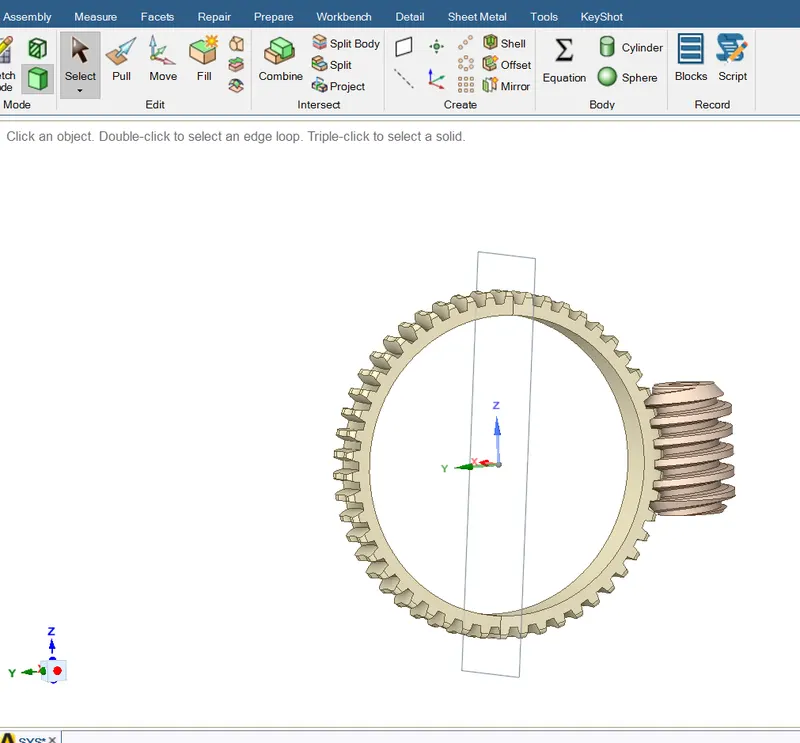
- Here for the acadmic version it can't load the whole gear so first we have to cut it from the half by using this plane and split body option. after split it shows like shown below.
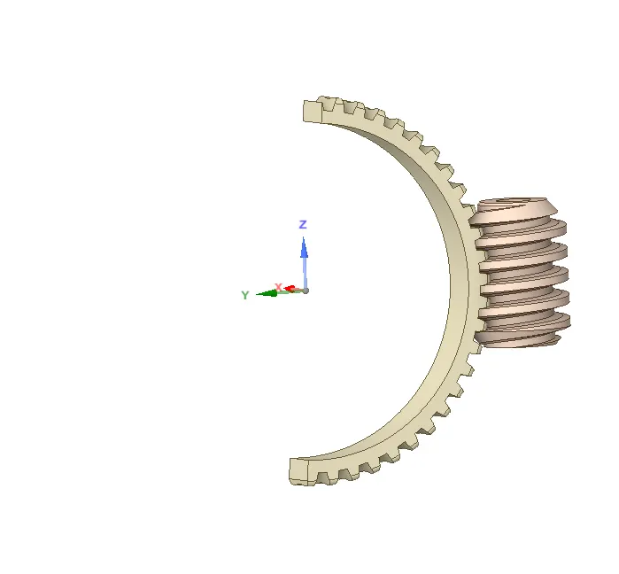
- After closing spaceclaim right click on model and click on update and then again double click on model and mechanicl will open as shown below.
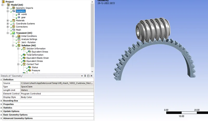
- Rename the parts as shown above.
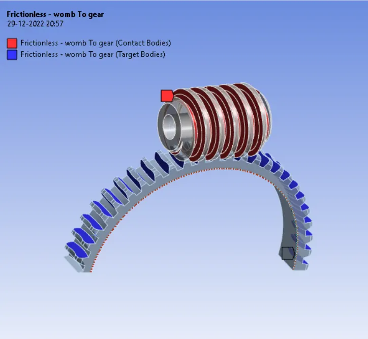
- After that we have to go to the connection and add frictionless contact as shown below and the setting is as it is no setting changes.
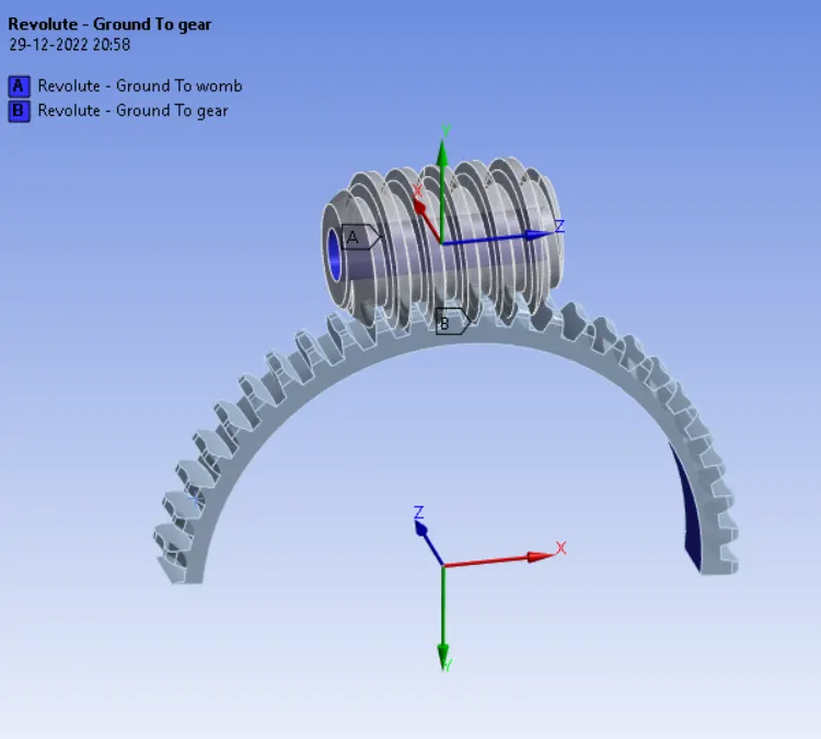
- After that add the joints here 2 body to ground revolute joints are added one is for womb and one is for gear.
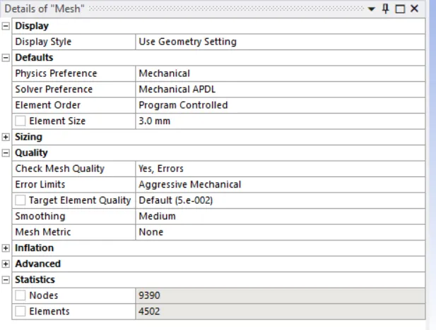
- After tha in the mesh setting i given the 3mm mesh size and the size of element and nodes are less then acadmic version,mesh looks good as hown below.
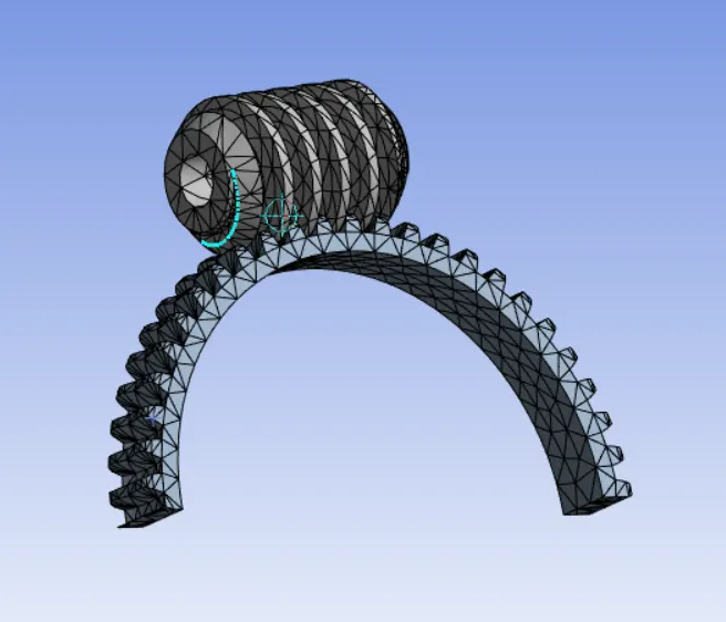
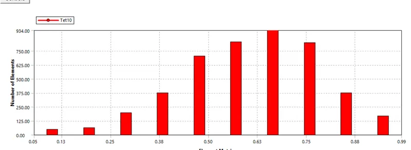
- The image shown above is mesh metrics for the quality of mesh.
- After that we go to the analysis setting where we take the total load step in 15 step and the setting shown below.
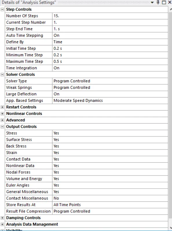
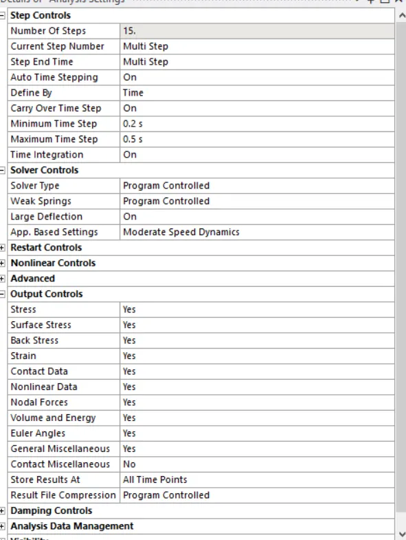
- This is for the first step and for 2nd to 15th as shown below.
- Now we have to give the boundry condition so only one boundy condition is given joint rotation inputed in tabular form as shown below.
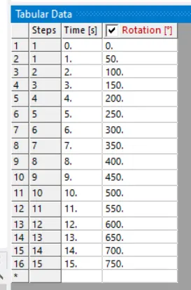
- Now after that add all the output results required and click on solve.
RESULTS:
Equivalent stress:
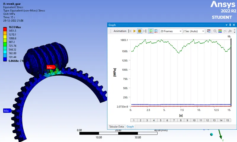
- Maximum equiv alent stress is generated near the contact teet is 1633 Mpa.
Equivalent strain:
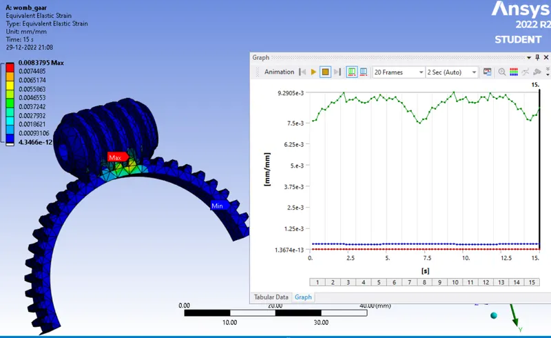
- The maximum equivalent strain is also generated near the teeth which is 0.0083795.
Total Deformation:
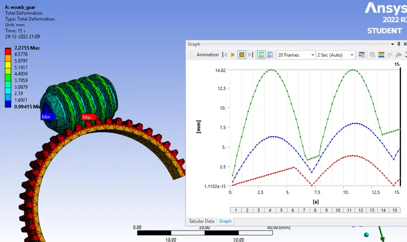
- Total deformation is max across the teets the max value is 7.2755 mm.
Conclusion:
- So we conclude that as per given criteria i had cutted the gear to half and run the womb upto half only.
- And all the results are shown above.